Simplex 4100U Installation & Maintenance
Fire indicator panel, fire alarm system
Hide thumbs
Also See for 4100U:
- Application manual (102 pages) ,
- Operator's manual (76 pages) ,
- Wiring diagrams (34 pages)

Related Manuals for Simplex 4100U


Summary of Contents for Simplex 4100U
- Page 1 Fire 4100U Fire Indicator Panel Fire Alarm System, Installation & Maintenance Australian Australian Installation & Installation Maintenance Manual Manual LT0350...
-
Page 3: Copyrights And Trademarks
6,313,744 and 6,426,697. SmartSync horn/strobe control; 6,281,789. Approvals Australian Standard AS4428.1 SSL Listing Number afp1682 Manufacture The 4100U is a Fire Alarm manufactured by Tyco Safety Products for: Tyco Services Fire & Safety 47 Gilby Road Notting Hill VIC 3168... -
Page 4: Non-Disclosure Agreement
“dongle”. Because this programming facility allows the user to define in detail the operation of the 4100U System being customised, changes may be made by the user that prevent this installation from meeting statutory requirements. -
Page 5: Model Number & Firmware Revision
This manual applies to product with the following: Model number : 4100U Firmware revision : 11.08 and on Document Document Name : LT0350 4100U Installation & Maintenance Manual Cross Reference : 574-848 4100U Installation Manual (USA) Issue : 1.0-G 14 May, 2004 Amendment Log 14 May, 2004 Issue 1.0.6 Original based on 574-848 Rev G... -
Page 6: Cautions, Warnings, And Regulatory Information
If damage is apparent, immediately file a claim with the carrier and notify your Simplex product supplier. SAFETY HAZARD - The 4100U CPU Card includes a lithium battery. There is danger of explosion if the battery is incorrectly replaced. Replace only with the same or equivalent type recommended by the manufacturer. -
Page 7: Table Of Contents
Cautions, Warnings, and Regulatory Information..........iv Table of Contents ....................v List of Figures ....................xiv List of Tables .....................xv Chapter 1 Introduction to the 4100U Fire Alarm System ..1-1 Introduction ....................1-1 In this Chapter ..................... 1-1 System Configurations ..................1-2 Overview...................... - Page 8 System Power....................2-8 The Power Distribution Interface (PDI)............2-8 Step 1. Mounting Cabinets (4100U) ..............2-9 Overview...................... 2-9 Step 2. Mounting Card Bays to Cabinets (4100U) .......... 2-9 Overview...................... 2-9 Step 3. Configuring Cards (4100U) ............... 2-10 Overview....................2-10 Master Motherboard Configuration............2-10 Master Controller Daughter Card Configuration........
- Page 9 Step 6. Installing LED/Switch Modules into Expansion Bays (4100U)..2-20 Overview....................2-20 The LED/Switch User Interface ..............2-21 LED/Switch Controller Card...............2-21 LED/Switch Modules.................. 2-22 Configuring the LED/Switch Controller Card ..........2-22 Activating the Communication Loss Feature..........2-22 Mounting LED/Switch Modules to the Expansion Bay ......2-23 Mounting the Controller Card Assembly............2-24...
- Page 10 Local Mode Specifications ................4-5 LEDs ......................4-6 Card Specifications..................4-6 MINIPLEX System Guidelines (4100U)............4-7 Overview...................... 4-7 Guidelines....................4-7 Configuring Cards (4100U)................4-8 Overview...................... 4-8 CPU Motherboard DIP Switch ..............4-8 TIC Configuration..................4-8 Configuring Other Cards................4-8 TIC/Riser Mounting (4100U)................4-9 Overview......................
- Page 11 Mounting ...................... 6-7 Configuration ....................6-8 Notes......................6-8 Warning ....................... 6-8 Specification ....................6-8 Chapter 7 SPS Field Wiring (4100U) ......... 7-1 Introduction ....................7-1 In this Chapter ..................... 7-1 General Field Wiring Guidelines..............7-2 General Guidelines ..................7-2 SPS NAC Field Wiring Guidelines..............7-3 Overview......................
- Page 12 IDNet Wiring ....................7-12 Guidelines....................7-12 Class A Wiring ................... 7-13 Class B Wiring ................... 7-14 Chapter 8 Installing 4100U IDNet & 4100MXP Cards ....8-1 Introduction ....................8-1 In this Chapter ..................... 8-1 The IDNet Card....................8-2 Overview...................... 8-2 LEDs ......................8-3...
- Page 13 AS4428 Requirements................10-2 Australian Panel Format ................10-3 Overview....................10-3 Australian / USA Differences ..............10-3 4100U/4100A Differences................10-3 4100U Fan Control Module ................10-4 Overview....................10-4 Labeling ..................... 10-4 Mounting & Connection ................10-4 Programming ..................... 10-4 Brigade Interfaces ..................10-6 Overview....................
- Page 14 Appendix A The Device Configuration DIP Switch....A-1 Overview......................A-1 Appendix B Programming Requirements ........B-1 Introduction ....................B-1 In this Chapter .....................B-1 Required Features ..................B-1 Notes......................B-1 Appendix C Checking System Wiring........C-1 Overview..................... C-1 Using the Volt/ Ohm Meter ................ C-1 Meter Readings ..................C-2 Appendix D Earth Fault Detection..........D-1 Overview.....................
- Page 15 Appendix G Compatible Batteries..........G-1 Appendix H 4100U Specifications..........H-1 General ....................... H-1 Fuses ......................H-1 Firmware Features..................H-1 Voltage & Current Ratings of Modules & Assemblies ........H-2 Appendix I Power Supply & Battery Capacity Calculations ... I-1 Power Supply....................I-1 Battery Capacity ...................
-
Page 16: List Of Figures
Expansion Bay Motherboard Placement ......... 2-16 Figure 2-11. Mixed Module Placement ............2-17 Figure 2-12. Slave Card/PDI Connection............. 2-18 Figure 2-13. Installing the Motherboard in a 4100U Expansion Bay.... 2-19 Figure 2-14. LED/Switch Modules..............2-21 Figure 2-15. LED/Switch Controller.............. 2-21 Figure 2-16. - Page 17 Figure 8-2. Mounting onto the Power Distribution Interface......8-4 Figure 8-3. Mounting into 4100 (legacy) Bay ..........8-5 Figure 8-4. DIP Switch SW1................. 8-6 Figure 8-5. Class A Wiring ................8-8 Figure 8-6. Class B Wiring ................8-9 Figure 9-1. Service and Diagnostic Interface ..........
-
Page 19: Chapter 1 Introduction To The 4100U Fire Alarm System
Introduction to the 4100U Fire Alarm System Introduction The 4100/4100U is an expandable fire alarm system that can be used as a standalone system with one host panel, or as a wide-ranging system with several remote cabinets, with or without multiple host panels. This chapter is an overview of standalone, MINIPLEX, and network 4100 system concepts. -
Page 20: System Configurations
System Configurations Overview The 4100U is available as a standalone system with one host panel, or as an expansive system with several remote back boxes, with or without multiple host panels. The type of configuration used depends on the size of the site into which it is being installed. -
Page 21: Standalone Configuration
Standalone Configuration Overview The standalone version of the 4100U is used for smaller or single-building applications. A standalone system is ideally placed into a small building that requires a limited number of notification appliances and initiating devices. If a small building is being expanded, or if other buildings are being constructed in the same general area (as in a campus application), the standalone 4100U can be expanded into one of the larger systems described later. -
Page 22: Miniplex Configuration
MINIPLEX. System Design The MINIPLEX 4100 FACP must contain the following: • • System Power Supply for the 4100U (Universal Power Supply for the 4100) • 4100 only (non-4100U): Remote unit interface (RUI) Card • Optional slave cards Each transponder cabinet, meanwhile, must contain a Transponder Interface Card (TIC) and any number of optional slave cards. -
Page 23: Rui Communication
(RTUs) in a MINIPLEX system by using the external RUI comms bus. An RUI line, routed from either the CPU Motherboard in the 4100U, or the RUI card in the 4100, allows the data to travel long distances. Once the RUI line terminates at a remote cabinet, the TIC (4100U) or RIC (4100) in that cabinet distributes the CPU’s data... -
Page 24: Network Configuration
Network Configuration Overview The 4100 can be expanded to a network system by using network interface cards (NICs). When a NIC is installed into a 4100 host panel, it is used to connect to other network nodes. Nodes may consist of other host 4100 panels, or they may be completely different: Graphical Command Centers (GCCs), and Visual Command Centers (VCCs) are all examples of what could be used as nodes. -
Page 25: Connecting Loops
Network Configuration, Continued Connecting Loops Network loops can be joined via physical bridge cards. There may be no more than two Style 7 network loops (two hub configurations) connected in tandem. For every two loops that are interconnected (using one physical bridge), there can be a maximum of three physical bridges used in a star configuration. -
Page 26: 4100 Pids (Non-4100U)
4100 PIDs (Non-4100U) The following is a list of existing 4100+/A cards and modules that may be used with 4100U. • 4100-5004 8 AZF Monitor Zone • 4100-0113 Dual RS232 Modem Interface • 4100-0110 MAPNET 2 Addressable Loop • 4100-3003 8 Relay Module •... -
Page 27: 4100U Cabinet Part Identification Numbers (Pids)
4100U Cabinet Part Identification Numbers (PIDs) Overview This section lists all cabinet (back box) PIDs for the 4100U Fire Alarm System. 4100U Cabinets Empty cabinets with Doors (Cream Wrinkle)/ Number of bays Number of bays that can be fitted: •... -
Page 28: Kits
KT0450 4100-4100U Upgrade, 19” RAC Mounting • KT0452 IDNet Mounted on 4100 Interface Bracket • KT0468 4100 MBd to 4100U Bay, Mounting Kit • KT0469 A5 Document Holder, Stick-On, 3U High, Grey Brigade Interfaces • KT0199 19”, 3U ASE Mounting Bracket, plus... -
Page 29: Chapter 2 Installing 4100U Facp Components
4100U cabinets are available in one-, two-, and three-bay sizes. Each can be equipped Introduction with a solid or perspex door. This chapter describes how to mount all types of 4100U cabinets to a wall, and how to mount system card bays into the cabinets, modules to bays, etc. -
Page 30: Introduction To Facps (4100U)
CPU Bay In the standard (USA) version of 4100U the CPU bay contains an SPS, the Master Motherboard with CPU Daughter card, but no PDI to which 4” x 5” cards (e.g. IDNet card) can be fitted. -
Page 31: Master Motherboard
Continued Master Motherboard The 4100U Master motherboard that houses the CPU card is central to the 4100U system. It mounts in the first bay, occupying four inches of space on the right hand side. Neither has a card address DIP switch (the CPU is address 0). -
Page 32: Master Controller Daughter Card
Introduction to FACPs (4100U), Continued Master Controller The master controller daughter card mounts onto the master motherboard. The master Daughter Card controller daughter card contains a service port, a direct drive user interface connection, and a port for a service modem. -
Page 33: Master Controller Daughter Card Leds
Introduction to FACPs (4100U), Continued Master Controller The master controller daughter card LEDs indicate Bootloader status as shown in the Daughter Card LEDs table below. Table 2-1. Master Controller LEDs 1 through 4 Status LED4 LED3 LED2 LED1 Condition Bootloader On (0.25s),... -
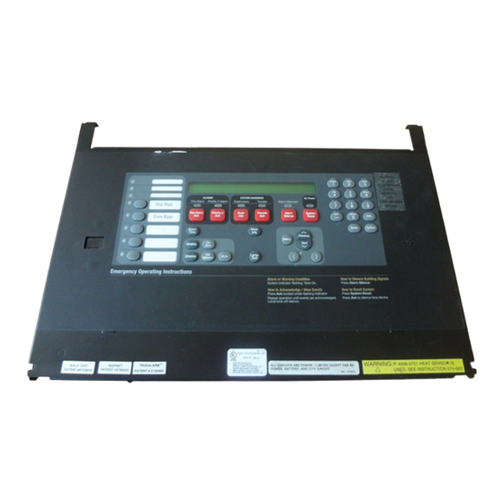
Page 34: Operator Interface
Introduction to FACPs (4100U), Continued Operator Interface The operator interface lets a user operate the panel. It provides alarm, trouble, and isolate status alerts, and lets the user review historical logs and perform diagnostics. Figure 2-3. Operator Interface Additional CPU The CPU bay can be equipped with many additional types of modules. -
Page 35: System Power Supply (Sps)
Introduction to FACPs (4100U), Continued System Power In the USA, a number of variants of power supply are available, e.g. SPS, RPS, XPS, Supply (SPS) XCharger each with different portions of circuitry (eg NACs, Battery Charger, IDNet) fitted or not fitted. In Australia, only one variant (SPS) is currently available, and it has hardware and software that are specific to Australia. -
Page 36: System Power
18Ahr (called little-uns), and 3.3A for batteries above 18Ahr (called big-uns). The “heavy” 24V Signal feed is only accessible via the NACs on the SPS, or via a wire harness. IMPORTANT: AC power must be provided to the 4100U from a dedicated branch circuit. The Power... -
Page 37: Step 1. Mounting Cabinets (4100U)
180°, then re-fitting the equipment. Step 2. Mounting Card Bays to Cabinets (4100U) Overview FACPs are ordered from the factory with bays and cards fitted as per the panel order spreadsheet. -
Page 38: Step 3. Configuring Cards (4100U)
Step 3. Configuring Cards (4100U) Overview The CPU, SPS, and all other modules to be mounted in the FACP cabinets must be configured to operate correctly in the system via their DIP switch and jumper ports. This section describes the hardware configuration for the CPU and SPS, since they will always be used in the CPU bay. -
Page 39: Pdi Configuration
Refer to the appropriate installation instructions to configure other cards that are located Cards in CPU and expansion bays. The 4100U ones are included in this manual. Refer to Appendix D for a list of publications. Step 4. Interconnecting Modules and Bays Overview Each card has to be interconnected with every other card in its bay. -
Page 40: Card Interconnections In The Cpu Bay
24V Card power and data to each 4”x 5” card. Interconnections Within Expansion Refer to “Step 7: Installing Modules into Expansion Bays (4100U)” for instructions on Bays mounting 4”x 5” cards to the PDI. Also bear in mind the following variations: •... -
Page 41: Connecting To Motherboards
Step 4. Interconnecting Modules and Bays, Continued Basic Bay-To-Bay Figure 2-7, below, shows the interconnections between three bays in a host panel. Interconnections (continued) From Previous PDI 4100 POWER DISTRIBUTION INTERFACE HARNESS ASSY 566-084 734-008 4100 POWER DISTRIBUTION INTERFACE ASSY 566-084 Figure 2-7. -
Page 42: Figure 2-8. Power And Communication Wiring For Motherboards
Step 4. Interconnecting Modules and Bays, Continued Connecting to Motherboards 2. Connect the other end of the harness to the leftmost motherboard in the next bay, (continued) as described below. Make sure to route the wiring on the left side of the bay. •... -
Page 43: Step 5. Installing Modules Into Expansion Bays (4100U)
Step 5. Installing Modules into Expansion Bays (4100U) Overview This section contains guidelines and instructions on installing 4”x 5” cards and traditional motherboards into 4100U card bays. IMPORTANT: This section applies to aftermarket modules for expansion bays only. If you do not need to install any aftermarket modules at all, and if you have followed Steps 1 through 6, you have completed the panel installation and can apply AC power. -
Page 44: Placement Guidelines
Step 5. Installing Modules into Expansion Bays (4100U), Continued Placement • Motherboards can be installed on top of the PDI in expansion bays. The data and Guidelines power that would normally be bussed via the PDI is instead routed across the boards (continued) via ribbon cable from one board to the next. -
Page 45: Figure 2-11. Mixed Module Placement
Step 5. Installing Modules into Expansion Bays (4100U), Continued Placement • As shown in the figure below, motherboards can be installed alongside Guidelines 4”x 5” cards, if necessary. (continued) Position Position Block E Slots 7 + 8 Slot 1 Slot 2... -
Page 46: Installing 4" X 5" Cards
Step 5. Installing Modules into Expansion Bays (4100U), Continued Installing 4” X 5” The power distribution interface (PDI) is mounted to the back of each expansion cabinet. Cards The PDI contains slots for up to eight 4”x 5” slave cards. Since the PDI carries power and data across the entire bay, it solves most interconnection issues, especially between 4”x 5”... -
Page 47: Figure 2-13. Installing The Motherboard In A 4100U Expansion Bay
64/64 LED/Switch Controller. The same applies to the modules made on the bay mounting bracket (FA2255), e.g. ME0426 T-Gen. METAL STANDOFFS SCREW HOLES PLASTIC STANDOFFS #6 SCREWS SCREW HOLES LOCKWASHERS Figure 2-13. Installing the Motherboard in a 4100U Expansion Bay 2-19... -
Page 48: Step 6. Installing Led/Switch Modules Into Expansion Bays (4100U)
Step 6. Installing LED/Switch Modules into Expansion Bays (4100U) Overview The LED/switch user interface consists of a variety of modules, mounted to the front of an expansion bay, which are configured via the 4100 Programmer. Each display module contains between 8 and 24 switches and LEDs, each one separately configurable. -
Page 49: The Led/Switch User Interface
Step 6. Installing LED/Switch Modules into Expansion Bays (4100U), Continued Below is an illustration of a LED/switch bay from the user’s perspective. The LED/Switch User Interface Figure 2-14. LED/Switch Modules LED/Switch The LED/switch controller card is a 4100 slave that mounts behind two LED/switch Controller Card modules. -
Page 50: Led/Switch Modules
Step 6. Installing LED/Switch Modules into Expansion Bays (4100U), Continued LED/Switch If more than 64 LEDs or 64 switches are used, a second controller may be installed. Controller Card, (continued) LED 1. This LED illuminates if communication loss between the controller and the CPU occurs. -
Page 51: Mounting Led/Switch Modules To The Expansion Bay
Step 6. Installing LED/Switch Modules into Expansion Bays (4100U), Continued Mounting Refer to the figure below to mount the display cards to the front of the expansion box. LED/Switch Modules to the Expansion ADDITIONAL LED/SWITCH CONTROLLER #6 UNC NUTS LOCKWASHERS... -
Page 52: Mounting The Controller Card Assembly
Step 6. Installing LED/Switch Modules into Expansion Bays (4100U), Continued Mounting the Refer to the figures and instructions below to mount the controller card assembly to the Controller Card back of one of the LED/switch cards. Assembly 4. Use four 322-123 Nuts and four 268-009 Washers to secure the 637-141 Bracket to the inside front of the expansion box. -
Page 53: Interconnecting Cards
Step 6. Installing LED/Switch Modules into Expansion Bays (4100U), Continued Changing Display Card LEDs, (continued) Figure 2-18. Assembling / Disassembling the LED Display Card Interconnecting User interface wiring consists of connecting the LED/switch controller card to the Cards expansion bay’s power distribution interface (PDI), and connecting display cards to each other. -
Page 54: Wiring Instructions
Step 6. Installing LED/Switch Modules into Expansion Bays (4100U), Continued Wiring Instructions The following directions are complete instructions on interconnecting display cards and connecting the controller card to a power source. 1. Use Harness 734-008 to connect P2 on the controller card to one of the 4-pin connectors on the PDI. -
Page 55: The Terminal Block Utility Module (4100U)
The Terminal Block Utility Module (4100U) Overview The 4100-0632 Terminal Block Utility Module is an all-purpose terminal block that mounts to an expansion bay, above or below the power distribution interface (PDI). Each module utilizes one block of mounting space. - Page 56 2-28...
-
Page 57: Chapter 3 Installing 4100 Miniplex Components (Non-4100U)
Installing 4100 MINIPLEX Components (Non-4100U) Introduction 4100 host panel and remote locations. This chapter describes the transponder installation procedure for all MINIPLEX systems in non-4100U systems. In this Chapter Refer to the page number listed in this table for information on a specific topic. -
Page 58: Introduction To Miniplex Systems (Non-4100U)
Introduction to MINIPLEX Systems (Non-4100U) Overview The 4100 MINIPLEX Fire Alarm System uses transponder cabinets containing remote interface cards (RICs) to extend power and communication across large areas. MINIPLEX transponders allow the system to provide applications for up to 1000 monitor and/or control points and 2000 annunciator points (see note). -
Page 59: Figure 3-1. Miniplex System Design
Introduction to MINIPLEX Systems (Non-4100U), Continued Overview (Continued) Seventh floor MINIPLEX transponder with solid door Legend: Sixth floor Speaker NAC TrueAlarm sensors and MAPNET II Fifth floor addressable circuits Audio riser wiring, twisted pair RUI communications wiring, twisted, shielded pair... -
Page 60: Miniplex System Components (Non-4100U)
MINIPLEX System Components (Non-4100U) Overview The 4100 MINIPLEX system is comprised of a host panel containing everything required in a standalone cabinet (see Chapter 2), plus: • An RUI module in the master controller bay • One or more remote MINIPLEX transponder cabinets •... -
Page 61: The Remote Interface Card (Ric)
MINIPLEX System Components (Non-4100U), Continued The Remote Remote interface cards (RICs) in the transponder cabinets allow for data, power, and Interface Card (RIC) audio interconnections between the 4100 host panel and remote locations. They support RUI connections in Style 4 and Style 7 wiring configurations. -
Page 62: Miniplex System Guidelines (Non-4100U)
MINIPLEX System Guidelines (Non-4100U) Overview The rules on this page apply exclusively to MINIPLEX systems. Review each guideline before installing a MINIPLEX 4100 system. Guidelines • The Style 4 RUI card supports MINIPLEX transponders and 4602/4603 serial annunciators on the same signaling line circuit. -
Page 63: Installing Modules Into Cabinets (Non-4100U)
Supply Figure 3-4. Installing the RUI Motherboard in the CPU Bay Note: RUI motherboards may also be installed in expansion bays. Refer to “Step 5: Installing Motherboards into Expansion Bays (Non-4100U)” in Chapter 2 for instructions. Continued on next page... -
Page 64: Installing The Ric Ii Motherboard
Installing Modules into Cabinets (Non-4100U), Continued Installing the RIC II The RIC II motherboard is installed into a remote transponder cabinet. Review the Motherboard following guidelines before mounting RIC II motherboard. • If a power supply is installed in the bay, it must be installed on the far right of the bay and any relay modules must be installed in the slots immediately to its left. -
Page 65: Connecting The 733-525 Harness
Installing Modules into Cabinets (Non-4100U), Continued Connecting the If you need to connect a 733-525 Harness to a motherboard, refer to Figure 3-6 and 733-525 Harness follow these steps. Make sure to route the power and communication wiring on the left side of the bay. -
Page 66: Figure 3-6. Power And Communication Wiring For The Transponder
Installing Modules into Cabinets (Non-4100U), Continued TO 24 VDC RIC II RIC II (565-233) (565-233) Connector with (OPTIONAL) Blue Wire Goes UNIVERSAL to P2 POWER SUPPLY Connector with White Wire Goes to P3 733-525 Harness 733-672 Harness Figure 3-6. Power and Communication Wiring for the Transponder Cabinet... -
Page 67: Miniplex Wiring (Non-4100U)
MINIPLEX Wiring (Non-4100U) Overview The RIC must be connected to the host panel via RUI cabling. This section explains how to wire the two together, and how to set up a system with multiple transponders connected to the same host panel. -
Page 68: Wiring Illustration
MINIPLEX Wiring (Non-4100U), Continued Wiring Illustration The illustration below applies to Class A and Class B wiring. 4100 MINIPLEX MASTER 562-856 W/565-217 +24 V 24 C COMMS "A" COMMS "B" RIC 11 RIC 11 565-233 565-233 Note 1 MINIPLEX MINIPLEX... -
Page 69: Chapter 4 Installing 4100U Miniplex Components
MINIPLEX transponder interface cards (TICs) allow for data and power interconnections between the 4100 host panel and remote locations. This chapter describes the transponder installation procedure for 4100U MINIPLEX systems. In this Chapter Refer to the page number listed in this table for information on a specific topic. -
Page 70: Introduction To Miniplex Transponders (4100U)
Introduction to MINIPLEX Transponders (4100U) Overview The 4100U MINIPLEX system is comprised of a host panel containing everything required in a standalone cabinet (see Chapter 1), plus: • One or more remote MINIPLEX transponder cabinets • A transponder interface card (TIC) in each transponder cabinet This section describes each component in turn. -
Page 71: The Local Mode Tic (Not Currently Available In Australia)
Introduction to MINIPLEX Transponders (4100U), Continued The Local Mode TIC The local mode TIC contains an RUI input, port for connecting to other transponder (Not currently modules, and terminal block for connecting to an optional Local Mode Controller. Local available in Mode Controllers are mounted remotely from the transponder. -
Page 72: Tic Illustrations
Introduction to MINIPLEX Transponders (4100U), Continued TIC Illustrations Below is an illustration of the various TIC and audio riser circuit boards. 4100-0620 4100-0625 BASIC TIC LOCAL MODE TIC DAR GROUND FAULT SEARCH ACTIVE LED1 LED1 LED2 CH1/DAR DIGITAL ON-ENABLE RISER... -
Page 73: Local Mode Specifications
Introduction to MINIPLEX Transponders (4100U), Continued Local Mode Local mode is supported by the following: Specifications • 4100-3101/3104/3105 IDNet Card • 4100-5101/5102/5103 Expansion Power Supply NACs (including TrueAlert Non-Addressable SmartSync appliances) • 4100-5111/5112/5113 System Power Supply NACs (including TrueAlert Non- Addressable SmartSync appliances) •... -
Page 74: Leds
Introduction to MINIPLEX Transponders (4100U), Continued LEDs The TICs have the following LEDs: LED1. Illuminates to indicate communication loss with the CPU. LED2. Illuminates when an RUI ground fault search is active. LED3. Illuminates when Local Mode is active. LED4. Illuminates to indicate an RUI Style 7 primary trouble. -
Page 75: Miniplex System Guidelines (4100U)
• Up to 4 RUI cards in the 4100U Control Panel can be used for distributing transponder wiring in different directions or for supporting different wiring requirements (such as using a Style 7 RUI for serial annunciators). -
Page 76: Configuring Cards (4100U)
Configuring Cards (4100U) Overview The TIC and all other cards to be mounted in the transponder cabinet and attached expansion bays must be configured to operate correctly in the system via their DIP switch and jumper ports. The CPU motherboard may have to be configured as well. -
Page 77: Tic/Riser Mounting (4100U)
TIC/Riser Mounting (4100U) Overview All TICs are mounted like any 4-inch (102 mm) X 5-inch (127 mm) card. This section describes the TIC/audio riser card mounting procedure, which is identical to that of other 4-inch (102 mm) X 5-inch (127 mm) cards. -
Page 78: Tic/Motherboard Interconnections (4100U)
TIC/Motherboard Interconnections (4100U) Use Figure 4-3 to connect the TIC to a motherboard in another bay. TMPR SW 24C INPUT SHLD POWER/ LED4 LED5 COMM HARNESS 734-078 4100 LED1 COMM LOSS LED2 G.F. SEARCH PDI 1 AUDIO RISER CARD 4100 POWER DISTRIBUTION INTERFACE... -
Page 79: Rui Wiring (4100U)
RUI Wiring (4100U) Overview The TIC must be connected to the host panel via RUI cabling. This section explains how to wire the two together, and how to set up a system with multiple transponders connected to the same host panel. - Page 80 4-12...
-
Page 81: Chapter 5 Networking
Chapter 5 Networking Introduction A standalone or MINIPLEX 4100 system becomes a network node when a 4100 Network Interface Card (NIC) or other compatible network card is installed and connected to another network node. How network cards connect to each other depends on the type of media network cards being used. -
Page 82: Getting Started
Getting Started Overview This chapter describes how to turn a standalone or MINIPLEX FACP into a network node. This process consists of the following: Step 1. Configuring cards for operation (using DIP switches and jumper ports) Step 2. Mounting media cards to the network interface card (NIC) Step 3. -
Page 83: Overview
Introduction to the 4100 Network Interface Card (NIC) Overview The Network Interface Card (NIC) is a slave card that uses the standard 4100 serial bus to communicate with the master. The NIC connects FACPs in a network, allowing for communication between each panel via fiber, modem, or twisted shielded pair wire. The NIC is designed to be connected in a point-to-point arrangement, so that one wire fault does not cause the entire system to fail. -
Page 84: Network Module Illustrations
Introduction to the 4100 Network Interface Card (NIC), Continued Network Module Illustrations DATA TRANSMIT/ RECEIVE LEDs (LED2 THROUGH LED5) MEDIA CARD 40-PIN CONNECTORS (P5, P6) DATA RATE JUMPER PORT (P3) DATA PROTOCOL JUMPER PORT (P3) MOTHERBOARD CONNECTOR (P4) ADDRESS DIP SWITCH (SW2) YELLOW LED DIAL-UP... -
Page 85: Nic Motherboards
Introduction to the 4100 Network Interface Card (NIC), Continued NIC Motherboards The figures below are illustrations of two motherboards apart from the default CPU motherboard that can be used with the 4100 NIC. • The 565-274 Master Motherboard holds two daughter cards: the 4100 master controller card and the 4100 NIC. -
Page 86: Nic Media Cards
Introduction to the 4100 Network Interface Card (NIC), Continued NIC Media Cards There are two approved modules that can be plugged into the 4100-6014 NIC: • 4100-6057 Fiber-Optic Media Card (565-261) • 4100-6056 Wired Media Card (565-413) Each module is shown below. FIBER-OPTIC DATA: 40-PIN NETWORK TRANSMIT (U1),... -
Page 87: Requirements And Limitations
Introduction to the 4100 Network Interface Card (NIC), Continued Requirements and Limitations Table 5-1. 4100 NIC & Media Cards - Electrical and Environmental Specifications Electrical Specifications Network Startup, no media cards: 8 VDC @ 110 mA Interface Card Nominal, no media cards: 20 to 32 VDC @ 0 mA Using 24 V power supply: 20 VDC @ 140 mA max. -
Page 88: Nic Card Jumper Settings
Step 1. Configuring Network Cards, Continued NIC Card There are two shunt jumper ports on the NIC card that need to be set: P3 and P4. Jumper Settings P3: Determines the NIC data transmission rate, 57.6 kbits/second or 9600 bits/second. •... -
Page 89: Step 2. Mounting Media Cards To The Nic
Step 2. Mounting Media Cards to the NIC Overview The 4100-6014 Network Interface Card (NIC) uses media cards to connect to other NICs. This section describes how the media cards are mounted onto NICs. Media Card NICs connect to each other via the three types of media cards. The types of media cards Mounting in the right and left ports are determined by the type of wiring that is being used across cards. -
Page 90: Step 3. Mounting Network Cards
Step 3. Mounting Network Cards The 4100 NIC daughter card, shown in Figure 6-8 below, inserts into motherboards as follows: • If the 565-274 Master Motherboard is being used, the NIC daughter card is inserted into connector J1. • If the 566-227 Master Motherboard or 565-275 Motherboard is used, the NIC daughter card is inserted into connector J2. -
Page 91: Step 4. Wiring Network Cards
Step 4. Wiring Network Cards Overview The nodes in the network now have to be wired together, so that the NIC in one host panel connects to the NIC in the next panel. This section contains guidelines and instructions for NIC wiring. Wiring Guidelines Refer to the following guidelines whenever field wiring the NICs. -
Page 92: Wiring Distances
Step 4. Wiring Network Cards, Continued • 655-158 Transient Suppressor (ordered as part of 748-599) is required for each modem-to-telephone line connection. From Modem Transient Suppressor Assembly (655-158) added to RJ-31x as shown. If connecting to a terminal block, cut off one end of the cable. Strip back the cable to connect the two center wires, normally red and green, to the red and green wires in the block. -
Page 93: Fiber-Optic Wiring
Step 4. Wiring Network Cards, Continued Fiber-Optic Wiring Connectors U1 (transmitter) and U2 (receiver) on the 4100-6057 Fiber-Optic Media Card are used to connect 4100-6014 NICs across parts of a network. Note: ST connectors with long strain relief boots are to be used with the fiber optic cable. -
Page 94: 4190-9010 Coupler Requirements
Step 4. Wiring Network Cards, Continued 4190-9010 Coupler The 4190-9010 Coupler (271-012) is used with the 565-261 Fiber Optic Media Board, Requirements revision “C” or higher. Two 4190-9010 Bi-Directional Couplers are required per connection, one at each node. The 4190-9010 is equipped with type ST connectors. To make type ST to type ST connections, an ST to ST coupler, by others, is required. -
Page 95: Wiring With The Wired Media Card
Step 4. Wiring Network Cards, Continued 4190-9010 Coupler The illustration below shows coupler wiring. Requirements (continued) Figure 5-10. Coupler Wiring Wiring with the Refer to the guidelines and figures in this topic to use wired media cards. Wired Media Card IMPORTANT: TB1 on the wired media card must not be used when it is connected to the 4100-6014 NIC. -
Page 96: Table 5-5 566-227 Cpu Motherboard Wired Media Connections
Step 4. Wiring Network Cards, Continued Wiring with the The Table below lists the 4100U master motherboard connections for the wired media Wired Media Card card. (continued) Table 5-5. 566-227 CPU Motherboard Wired Media Connections Motherboard Port for Media Wired Media Card Connection... -
Page 97: Wiring Illustrations
Continued Wiring Illustrations The figures below show how to wire the NIC. The illustrations use the 565-274 and 565- 275 motherboards only. If you are using the 4100U motherboard, refer to Figure 5-11 along with the figures below. Wired Media,... -
Page 98: Fiber Optic, Style 7 Wiring
Refer to general wiring precautions in this chapter, as well as Field Wiring Specifications: document 900-082 for 4100; 900-242 for 4100U. For specific information about fiber optic wiring, refer to the 900-143 Fiber Tutorial. The maximum distance between nodes when using the fiber communication path is dependent upon the fiber’s multimode graded index: 10,000 feet (3,048 m) for 50/125 fiber;... -
Page 99: Wired Media And Fiber Optic, Style 7 Wiring
Refer to general wiring precautions in this chapter, as well as Field Wiring Specifications: document 900-082 for 4100; 900-242 for 4100U. For specific information about fiber optic wiring, refer to the 900-143 Fiber Tutorial. The maximum distance between nodes when using the fiber communication path is dependent upon the fiber’s multimode graded index: 10,000 feet (3,048 m) for 50/125 fiber;... - Page 100 5-20...
-
Page 101: Chapter 6 The System Power Supply & Alarm Relay Card
Chapter 6 The System Power Supply & Alarm Relay Card Introduction The SPS is described in Chapter 2. A picture is shown in Figure 2.4. This chapter has the current and voltage ratings of the system power supply (SPS) and describes how it is installed and configured by the factory. -
Page 102: Sps Specifications
3.3 A (Default; for 18-110 Ah battery) Notes: • AC power must be provided to the 4100U from a dedicated AC branch circuit. The AC input is supervised. • 240 VAC: The service branch circuit breaker should be sized to handle at least 150 percent of the total required by all of the power supplies in the system. -
Page 103: Sps Current Consumption
SPS Specifications, Continued • +24V Sig is used to supply the NACs. It can be made accessible by configuring a NAC as an aux power output (normally energized). The PDI has a 24V Sig bus that is only powered when an SPS is plugged directly on to it. -
Page 104: Environmental Requirements
SPS Specifications, Continued Environmental The range of possible temperatures under which the SPS may function are between 0° C Requirements and 50° C (120° F). The SPS operates normally under non-condensing humidity conditions up to 93% with relative humidity at 32° C. SPS Configuration Overview This section contains information about SPS jumpers, DIP switches and potentiometers. -
Page 105: Sps Led Indications
SPS LED Indications LEDs The SPS has the following LEDs: LED1 (yellow). Illuminates when NAC 1 is ON or in Fault. LED2 (yellow). Illuminates when NAC 2 is ON or in Fault. LED3 (yellow). Illuminates when NAC 3 is ON or in Fault. LED4 (yellow). -
Page 106: Troubleshooting On Sps
Troubleshooting on SPS Overview This section contains explanations of fault messages that may appear on the 4100U display when using the SPS. Heading text in the left margin shows the error message, while the paragraph next to it describes the likely cause of the message. -
Page 107: The Alarm Relay Card
The Alarm Relay Card Overview The Alarm Relay Card mounts on, and is driven by, the SPS. It has 3 relays each providing one set of voltage-free contacts. The relays are able to be configured under custom control, but the default operation is for system status, i.e. -
Page 108: Configuration
The Alarm Relay Card, Continued Configuration The relays have one set of voltage-free contacts (see note below) connected to one pair of terminals via a header. The two terminals are configured for normally closed or normally open by positioning a jumper on the header. Table 6-3. -
Page 109: Chapter 7 Sps Field Wiring (4100U)
Chapter 7 SPS Field Wiring (4100U) Introduction This chapter shows how various devices are wired to an SPS. It includes connection to NACs, IDNet, relays, and power circuits. In this Chapter Refer to the page number listed in this table for information on a specific topic. -
Page 110: General Field Wiring Guidelines
General Field Wiring Guidelines General Guidelines Make sure these guidelines are accounted for before wiring: • All field wires must be 0.75 mm or greater and comply with AS1670.1 and the wiring code. • Conductors must test free of all grounds. •... -
Page 111: Sps Nac Field Wiring Guidelines
LCD. The Australian SPS has extra decoupling capacitors fitted to the NAC outputs, and cannot be used to drive the Simplex range of addressable appliances. NACs may be programmed to be normally on and the terminals used as power supply outputs. -
Page 112: Class A Nac Wiring
SPS NAC Field Wiring Guidelines, Continued Class A NAC Wiring To connect the SPS to reverse-polarity, non-addressable notification appliances using Class A wiring, read the following instructions and refer to the figure below. 1. Route wire (between 0.75 mm and 4 mm ) from the “B+”, “B-”, outputs on TB2 of the SPS to the appropriate inputs on a peripheral notification appliance. -
Page 113: Class B Nac Wiring
Class B NAC Wiring To connect the SPS to appliances using Class B wiring, read the following instructions and refer to the figure below. 1. Route wire (between 0.75 mm and 4 mm ) from the B+, B- outputs on TB2 of the SPS to the appropriate inputs on a peripheral notification appliance. -
Page 114: Class A Nac Wiring Table
Class A NAC Table 7-1 lists the maximum distances from the NAC terminal block to the last appliance Wiring Table in a Class A configuration, depending on wire gauge and current. Use Table 7-1 to calculate wire distances for your application if you are using Class A wiring. Table 7-1. -
Page 115: Class B Nac Wiring Table
Power Supply Wiring Distances, Continued Class B NAC Table 7-2 lists the maximum distances from the NAC terminal block to the last appliance Wiring Table in a Class B configuration, depending on wire gauge and current. Use Table 7-2 to calculate wire distances for your application if you are using Class B wiring. -
Page 116: Sps Auxiliary Power Wiring
SPS Auxiliary Power Wiring Overview The panel, battery-backed, unregulated dc bulk power is available from the SPS via the NAC and the 24V Aux power terminals (1 pair only, ref fig 7-4). NACs not configured as switched outputs may be configured as auxiliary power point type in the 4100 Programmer. -
Page 117: Wiring
SPS Auxiliary Power Wiring, Continued Wiring The SPS can connect to auxiliary power appliances via the dedicated auxiliary power tap (TB3). If more power is needed, any of the three NAC outputs can be used for EMC auxiliary power. AUXILIARY AUXILIARY AUXILIARY POWER... -
Page 118: Sps Relay Wiring
SPS Relay Wiring Overview The SPS has one programmable relay, Aux 1, with one set of voltage-free contacts (see below). It also has provision for mounting a 4100-6033 Alarm Relay that has 3 relays, each with one set of normally open (or normally closed) contacts available on a screw terminal block (see fig 6.1). -
Page 119: Relays
SPS Auxiliary Relay Wiring, Continued Relays The Figure below shows the SPS relays. B+ B- A+ A- B+ B- A+ A- B+ B- A+ A- ALARM RELAY MODULE Dedicated Auxiliary 1 relay terminal block NO C NC TERMINAL BLOCK Figure 7-5. Auxiliary Relay & Alarm Relay Card Relays 7-11... -
Page 120: Sps Idnet Wiring
SPS IDNet Wiring Overview This section describes how the IDNet on the SPS connects to addressable devices/detectors. The guidelines governing IDNet wiring guidelines are covered in chpt 8, IDNet Installation. IDNet Wiring Up to 250 IDNet initiating devices are supported on the SPS IDNet channel. The SPS supports both Class A (loop) and Class B(string) wiring. -
Page 121: Class A Wiring
SPS IDNet Wiring, Continued Class A Wiring To connect addressable devices/detectors to the SPS IDNet using Class A wiring, read the following instructions. 1. Ferrite beads are required on the SPS IDNet cables (ref Fig 7.1). 2. Route wire (between 0.75 mm and 4 mm ) from the B+, B- outputs on TB1 of the SPS to the appropriate inputs on a peripheral IDNet device. -
Page 122: Class B Wiring
SPS IDNet Wiring, Continued Class B Wiring To connect addressable devices/detectors to the SPS IDNet using Class B wiring, read the following instructions. 1. Under AS1670.1 Class B wiring is allowed only for a maximum of 40 addressable devices. 2. A ferrite bead is required on the SPS IDNet cable. 3. -
Page 123: Chapter 8 Installing 4100U Idnet & 4100Mxp Cards
Chapter 8 Installing 4100U IDNet & 4100MXP Cards Introduction Two loop cards are available in the 4100U 4”x 5”card format. These plug directly onto the PDI and form an intelligent interface between the 4100U CPU and one loop of addressable detectors/devices. -
Page 124: The Idnet Card
The IDNet Card Overview The 4100U IDNet card receives 24V power (+24V Card Supply bus) and coms (i.e. communication with the CPU) via the PDI. There are several versions, configured by links soldered on the pcb. The 4100-3101 used in Australia, communicates with up to 250 devices. -
Page 125: Leds
The IDNet Card, Continued LEDs The IDNet card has the following LEDs: LED1. Normally off. Turns on steady if the IDNet card is not communicating with the 4100 CPU. LED2. Normally off. Illuminates to indicate a problem with the IDNet lines. •... -
Page 126: Installing The Idnet Card Onto The Pdi
Installing the IDNet Card onto the PDI Overview The 4100-series IDNet card is designed to be mounted on the PDI in a 4100U expansion cabinet. The card can be mounted on any of the PDI connectors. Use connector P2, labeled on the back side of the IDNet card, to connect to any of the eight PDI connectors as shown in the figure below. -
Page 127: Overview
Installing the ID-Net into a 4100 Card Bay Overview If a 4100 is upgraded to 4100U, IDNet cards can be fitted to existing 4100 bays by use of the Interface Card plus bracket. The bracket mounts to the bay as a 4100 card motherboard does and takes up 1 slot. -
Page 128: Configuring The Card
Configuring the Card Overview Configuring the card consists of selecting the shield tie point, and setting the device address.. Setting the Shield If a shielded cable is used, connect the cable shield to the dedicated terminal on TB1 and Tie Point use jumper port (P1) to select where the shield will be tied. -
Page 129: Wiring To Idnet Devices
Wiring to IDNet Devices Overview Up to 250 IDNet slave devices, such as smoke detectors and manual call points, can be connected to the IDNet card using Class A (loop) or Class B (line) wiring, with the following restrictions. Class A wiring allows the devices to communicate with the IDNet card even in the event of an open circuit somewhere in the loop. -
Page 130: Notes
Wiring to IDNet Devices, Continued Table 8-2 Cable Run Lengths Wire Size 0.75 mm 1 mm 1.5 mm 2.5 mm 4 mm Resistance Distance 385 m 513 m 769 m 1,282 m 2,052 m 20Ω Distance 769 m 1,026 m 1,538 m 2,565 m 4,104 m... -
Page 131: Class B Wiring
Wiring to IDNet Devices, Continued Class B Wiring To connect the IDNet card to appliances using Class B wiring, read the following instructions. 1. On TB1, jumper IDNetB+ to IDNet A+, and jumper IDNetB- to IDNetA-. If the jumper is absent, a Class A Trouble will be indicated on LED 2. 2. -
Page 132: Troubleshooting On Idnet
Troubleshooting on IDNet Overview This section describes the messages that may appear on the 4100 display when using the IDNet card. Trouble messages appear on the left as titles, and possible causes are listed to the right in the text. IDNet Power There is no output voltage from the IDNet power supply. -
Page 133: The 4100Mxp
The 4100MXP The 4100MXP is a 4” x 5” card, similar to the IDNet, but allows the 4100U to Introduction communicate with a Loop of MX devices. The firmware in the 4100U sees the 4100MXP as an IDNet, and all the MX devices are matched to the nearest Simplex device. - Page 134 8-12...
-
Page 135: Introduction
Chapter 9 PC Software Connections Introduction The service port on the door with the Operator Interface enables the 4100U to connect to PCs running important utilities, such as diagnostics, programming, CPU firmware downloading, and channel monitoring. In this Chapter Refer to the page number listed in this table for information on a specific topic. -
Page 136: Software Modes
Software Modes Overview The 4100U can connect to PCs running important utilities, such as diagnostics, programming, CPU firmware downloading, and channel monitoring. It connects to PCs running all of these utilities via the service port on the CPU daughter card. When a PC is located remotely from the FACP, the 4100-9832 Service Modem is used. -
Page 137: Software Modes
Software Modes, Continued Software Modes Master Bootloader Interface Mode. This mode downloads the Master CPU Exec (continued) firmware and the CFG.TXT file to the CPU via the serial port. serial download cable Laptop/PC running 4100 Panel Laptop/PC running terminal emulation software programming file transfer running Bootloader Figure 9-3. -
Page 139: Chapter 10 Australian Version Specifics
Australian Version Specifics Introduction This chapter provides detail on format and components that are specific to the Australian version 4100U that complies with AS4428. In this Chapter Refer to the page number listed in this table for information on a specific topic. -
Page 140: Summary Of Australian Version Specifics
• limit the number of system components available in the Australian version. AS4428 The 4100U Operator Interface does not comply with the AS4428.1 requirements for an Requirements FF (Firefighter Facility) that uses only an alphanumeric display for alarm zone status indication. -
Page 141: Australian Panel Format
A revised version of this bracket has been designed to mount the T-Gen, two MiniGens or the 1948 PSU into a 4100U bay. It does not, however, take the two amplifiers. The Powerblock. PSU is not available in this form. -
Page 142: 4100U Fan Control Module
PC for local printing. LED names may also be revised. Mounting & The Fan Control module mounts to the frame of the 4100U Expansion bay door, from the Connection front, by the studs on the module with the nuts and washers provided. -
Page 143: Figure 10-1. Fan Control Module
Figure 10-1. Fan Control Module 10-5... -
Page 144: Brigade Interfaces
Brigade Interfaces Overview The Alarm Relay Card is typically used to provide a Brigade Interface. The default configuration is for the three relays to operate on Fault (Trouble), Isolate (Supervisory) and Alarm, respectively. The connection drawings for the Centaur ASE, Western Australia AIU and Queensland PPU are included in the appendix. -
Page 145: Chapter 11 Installation Checklist, Commissioning & Maintenance
Installation Checklist, Commissioning & Maintenance Introduction When a branch designs a system and orders a 4100U panel, a “Configuration Sheet” is prepared. The factory builds the panel to the configuration sheet. This includes fitting, connecting and configuring cards and modules. -
Page 146: Installation Checklist
Installation Checklist The following checklist should be completed by the installer. (Note that all pcbs are Overview electronically tested and adjusted before being fitted to the FIP). CABINET & GENERAL Cabinet colour - Standard Cream Wrinkle (BFF 998 CW) - Other: ____________________________________ Cabinet undamaged (Paint OK) Door aligned correctly Window undamaged and fitted correctly... -
Page 147: Overview
Alignment & Adjustment All the 4100U cards and modules (pcbs) are tested and aligned in the factory before being Overview supplied to the customer or fitted to a FIP. The only field adjustment that may be necessary is to set the battery charger voltage. (Note this has been set and should not need re-adjusting). -
Page 148: Power Up & Placing Into Operation
Power Up & Placing into Operation To place the 4100U FACP into operation, perform the following steps: STEP 1 Ensure that the Mains Isolate Switch is OFF. STEP 2 Ensure that 240 VAC is connected to the panel from the mains distribution switchboard. -
Page 149: Maintenance
Maintenance The 4100U system must be kept free from faults and tested on a weekly, monthly and annual basis to verify that it is operating correctly. The tests required by part 8 of the standard AS1851 Maintenance of Fire Protection Equipment are detailed in the 4100U Operator’s Manual, LT0351. - Page 150 11-6...
-
Page 151: Appendix A The Device Configuration Dip Switch
Appendix A The Device Configuration DIP Switch Overview Addressable cards include a bank of eight DIP switches. From left to right (see Figure A- 1, below) these switches are designated as SWx-1 through SWx-8. The function of these switches is as follows: •... -
Page 152: Table A-1 Card Addresses
Overview, (continued) Table A-1. Card Addresses Address SW 1-2 SW 1-3 SW 1-4 SW 1-5 SW 1-6 SW 1-7 SW 1-8 Address SW 1-2 SW 1-3 SW 1-4 SW 1-5 SW 1-6 SW 1-7 SW 1-8... -
Page 153: Appendix B Programming Requirements
This appendix identifies the programming that is required to comply with AS4428. It does not provide equations or detail of programming. The separate 4100 Programming Unit Manual tells how to use the PC-based 4100U Programmer. In this Chapter Refer to the page number listed in this table for information on a specific topic. -
Page 154: Appendix C Checking System Wiring
Ohm Meter and instructions below. Notes: • Ensure that no power is applied to the 4100U fire alarm panel and that all wiring is properly connected (terminal blocks, LED/switch module ribbon cables, etc.). • Use the earth stud in the control panel for all measurements to ground. -
Page 155: Meter Readings
Appendix C: Checking System Wiring, Continued Meter Readings Table C-1 lists the correct meter readings for indicating appliances and initiating devices. Table C-1. Acceptable Zone and Signal Circuit Meter Readings Circuit Type Meter Reading Class B/Style B Initiating Device (Zone) Circuit From zone + to zone –... -
Page 156: Appendix D Earth Fault Detection
Earth Fault Search is conducted by the FACP. The diagnostic may be activated using either the front panel interface or the Computer Port Protocol (CPP), via a service port. The 4100U supports two types of Earth Fault Searches: • Location Search. Searches all circuits at a location, such as a transponder or the main panel. -
Page 157: General Guidelines
At the completion of the search, all slaves are restarted and normal panel operation resumes. • Earth Fault Search is only supported by new 4100U modules. 4100 Legacy (slot format) modules are not supported, with the following exceptions: MAPNET channel isolation during location search IPS for earth fault detection (not recommended). -
Page 158: Earth Fault Searching From The Front Panel
Earth Fault Searching from the Front Panel Overview This section describes how to conduct an Earth Fault Search, from selecting the appropriate access code to correcting the fault. Access Level The panel must be at the appropriate access level (1, 2, 3, or 4) in order to run diagnostics. Selection To get to the correct access level, 1. -
Page 159: Search Option A: Select Location
Earth Fault Searching from the Front Panel, Continued 8. Press the Enter button. The following options become available when you press Starting the Earth the Next and Previous buttons: Fault Search, Continued Press <NEXT> or <PREVIOUS> to scroll Location Search Press <NEXT>... -
Page 160: Search Option B: Select Channel
Earth Fault Searching from the Front Panel, Continued Search Option B: If you select the IDNet Channel Search menu item, a list of IDNet channels to search Select Channel becomes available. Use the Next and Previous buttons to scroll through the list. When the IDNet channel you want to search is shown and "Press <ENTER>... -
Page 161: Search Results
Search Results Overview There are several types of results that can display at the end of an Earth Fault Search. This section covers all types of results. IMPORTANT: Once you have been directed to an earth ground fault and corrected it, it is recommended that you restart the system (warm- or cold- start). -
Page 162: Fault Not Found
Search Results, Continued Point Faults, 4009 IDNet NAC Extender/TrueAlert Addressable Controller faults. The message Continued below shows a fault detected on the 4009 IDNet NAC Extender before the repeater connected to that circuit is turned on: CARD 2, IDNET CARD (250 POINTS) M1-18, 4009A NAC EARTH FAULT Conversely, the following example shows a fault detected after the repeater connected to... -
Page 163: Earth Fault Search Example
Earth Fault Search Example The illustration below shows a MINIPLEX system with one transponder that has three earth faults: • SPS NAC on the SPS in the Main Panel • RPS AUXPWR output on the RPS in Transponder 1 • IDNet channel in Transponder 1 NAC 2 Main... - Page 164 Search Results, Continued B. Find and repair the indicated fault on Transponder 1. 1. Select Location Search. 14. Select the RPS located in Transponder 1 (this selects Transponder 1 as the location for the search). 15. When prompted, select exclusion of AUXPWR circuits. 16.
-
Page 165: Appendix E Related Documentation
LT0313 4100 MXP Engineering/Technical Manual LT0314 4100 MXP Installation Instructions LT0351 4100U Operators Manual (For ordering, LT0351 is A5, LT0351A4 is A4.) The following is a complete listing of US 4100U documentation. Book Part Title Number 4100/4120-0136 and 4100-6045 Decoder Modules... - Page 166 Installation Instructions 4100U Flex Amplifiers 579-173 Installation Instructions 4100U Digital/Analog Amplifiers 579-174 Installation Instructions 4100U Class A and Expansion NAC Modules 579-175 Installation Instructions 4100/4120-Series NIC and Media Modules 579-182 Installation Instructions 4100/4120-Series Physical Bridges and 4100/4120-Series Media Modules 579-184...
- Page 167 Appendix E: Related Documentation, Continued Book Part Number Title (cont.) (cont.) 4100U Class A and Expansion NAC Modules 579-175 Installation Instructions 4100U Upgrade Kits 579-229 Installation Instructions 4100U SPS/RPS 579-246 Installation Instructions 4100-0632 Terminal Block Utility Module 579-248 Installation Instructions...
-
Page 168: Appendix F Compatible Actuating Devices
Topic See Page # List of Approved Devices Compatible Detectors, IDNET Compatible Addressable Field Devices, IDNet List of Approved Devices Simplex Range - Conventional Detectors 4098-9413 Heat detector Type A 4098-9414 Heat detector Type B 4098-9415 Heat detector Type C... - Page 169 List of Approved Devices, Continued Hochiki Range - Conventional Detectors DCA-B-60R MK V Type A heat detector DCC-A Heat Type A DCC-C Heat Type C DCD-A Heat Type A DCD-C Heat Type C DFE-60B Type B heat detector DCA-B-90R MK 1 Type C heat detector DFE-90D Type D heat detector...
- Page 170 Cerberus Range - Conventional Detectors D01191A Beam DL01191A Beam The following range of detectors may be used with MAPNET Modules. Simplex Range - Analog Addressable Sensors 4098-9701 High / Very High sensitivity Photoelectric smoke 4098-9716 Ionisation smoke 4098-9731 Type A / Type B Heat...
-
Page 171: Compatible Detectors, Idnet
List of Approved Devices, Continued Simplex MAPNET 2 Range – Addressable Field Devices 2190-9156 Mapnet 2 Monitor ZAM 2190-9162 Mapnet 2 Signal ZAM 2190-9164 Mapnet 2 Control ZAM 2190-9169 Mapnet 2 Line Powered Short Circuit Isolator 2190-9172 Mapnet 2 Supervised IAM... -
Page 172: Compatible Addressable Field Devices, Idnet
Compatible Addressable Field Devices, IDNet The following lists the addressable devices approved for use with IDNet and shows current rating and numbers allowed per loop. Device Type Operating Maximum Maximum Current mA Addressable Addressable Point On Points on Analogue Loop Analogue Line 4090-9116 IDNet Comms Isolator... -
Page 173: Appendix G Compatible Batteries
Appendix G Compatible Batteries The following batteries are compatible with the 4100U. • Power Sonic PS12 Series • Century Power Sonic PS12 series • Sonnenschein A200 Series • Sonnenschein A300 Series • Century Yuasa NP Series • Auscell CJ12 series •... -
Page 174: Appendix H 4100U Specifications
Appendix H 4100U Specifications General System Capacity 2,000 points of addressable points, plus 2,000 points of annunciation. Expansion Up to capacity above. Up to 119 Addressable cards Cabinet Size Dependent on system configuration Cabinet Material 1.6mm Zintex Cabinet Finish Powder coated... -
Page 175: Voltage & Current Ratings Of Modules & Assemblies
Voltage & Current Ratings of Modules & Assemblies The DC input voltage range of the following modules is 18-33Vdc. The current listed is nominal for 24Vdc, and may be used for battery capacity calculations. Module Name Quiescent Alarm Master Controller Assembly 373mA 470mA (includes SPS, CPU, CPU Motherboard... -
Page 176: Appendix I Power Supply & Battery Capacity Calculations
Appendix I Power Supply & Battery Capacity Calculations Power Supply Part of the system design includes calculating that the quiescent load and the alarm load are each less than the rating of the power supply. Note that the quiescent load includes devices such as door holders that are normally energized, but get switched off during alarm. -
Page 177: Appendix J Cable Characteristics
Appendix J Cable Characteristics IDNet The IDNet cabling requirements are detailed in Chapter 8 of this manual. Line Characteristics 4100 MAPNET II Note: In the following paragraphs the term "MAPNET channel" is used to mean those lines connected to any one Mapnet Transceiver board. Parallel runs from the same board do not constitute separate channels. - Page 178 Network, Continued Fibre Optic Cable Characteristics All fibre cables shall be multimode, graded index. ST style connectors must be used. No physical strain shall be put on the cables. There must be no cable bends of less than a 50mm radius. Two methods are available for joining fibre cable.
-
Page 179: Appendix K List Of Drawings
Appendix K List of Drawings The following drawings are included and are referred to in the manual or are considered relevant. 1901-267 Sheet 2, 4100U AIU/PSU Wiring Assembly Drawing 1919-22 RAC Cabinet Mounting Drawing 1963-51 KT0193 3U RAC Mounting ASE Drawing... - Page 180 ©2004 Tyco Safety Products Westminster, Westminster, MA 01441-001 USA. Specifications and other information shown were current as of publication, and are subject to change without notice.
Need help?
Do you have a question about the 4100U and is the answer not in the manual?
Questions and answers