Simplex 4100U Operator's Manual
Hide thumbs
Also See for 4100U:
- Installation & maintenance (180 pages) ,
- Application manual (102 pages) ,
- Wiring diagrams (34 pages)

Related Manuals for Simplex 4100U


Summary of Contents for Simplex 4100U
- Page 1 FIRE F I R E 4100U Fire Alarm Operator's Manual 579-197 574-xxx Rev. B Rev. 4 Technical Manuals Online! - http://www.tech-man.com firealarmresources.com...
- Page 2 Blank Page- Back of Front Cover Technical Manuals Online! - http://www.tech-man.com firealarmresources.com...
- Page 3 Simplex Time Recorder Company. Simplex and the Simplex logo are registered trademarks of Simplex Time Recorder Co. Technical Manuals Online! - http://www.tech-man.com...
- Page 4 Product operation and reliability depends upon proper installation. DO NOT INSTALL ANY SIMPLEX PRODUCT THAT APPEARS DAMAGED. Upon unpacking your Simplex product, inspect the contents of the carton for shipping damage. If damage is apparent, immediately file a claim with the carrier and notify Simplex.
-
Page 5: Table Of Contents
Table of Contents How to Use this Publication.................... ix Introduction ......................... ix General Conventions ....................ix Keyboard Conventions ....................ix Using the Mouse......................x Chapter 1 Basic Concepts and Operations........1-1 Introduction ......................1-1 In this Chapter ......................1-1 Basic System Description.................... 1-2 Overview........................ - Page 6 Globally Acknowledging Troubles ................3-4 Individually Acknowledging Troubles............... 3-4 If the Trouble Doesn’t Clear..................3-6 Overview........................3-6 System Reset Key ....................3-6 Disabling a Point with a Trouble Condition.............. 3-6 Chapter 4 Supervisory Conditions............4-1 Introduction ......................4-1 In this Chapter ......................4-1 Overview........................
- Page 7 Forcing Points On and Off ................... 6-8 Overview........................6-8 Forcing Points ON and OFF ..................6-8 Returning a Point to Automatic Operation ............... 6-8 Displaying and Clearing Historical Logs..............6-9 Overview........................6-9 Displaying/Clearing Historical Logs ................. 6-9 Printing Reports ......................6-10 Overview........................
- Page 8 Resetting the Audio System ..................8-6 Two Channel Audio Operation ..................8-7 Overview........................8-7 Evacuate Entire Building..................8-8 Evacuate Specific Floors when No Alarms are Present.......... 8-8 Evacuate Additional Floors During an Alarm............8-8 Alert Specific Floors....................8-8 Evacuate Floors On Which Alert Message is Playing ..........8-9 Page Entire Building ....................
-
Page 9: How To Use This Publication
How to Use this Publication Introduction Before you start using the 4100 Fire Alarm Operator’s Manual, it's important to understand the typographic conventions used in this publication. General The following conventions are used in this publication to identify special names or text. Conventions Convention Meaning... -
Page 10: Using The Mouse
How to Use this Publication, Continued Using the Mouse The following table lists four common terms related to mouse operation that you should know. Use the left mouse button for all actions unless instructed otherwise. Note: When using the mouse button to point, click, or drag, keep the mouse steady; otherwise, you may select the wrong item. -
Page 11: Chapter 1 Basic Concepts And Operations
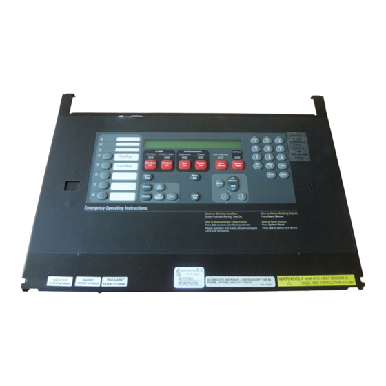
Chapter 1 Basic Concepts and Operations Introduction This chapter provides an overview of the 4100 operator interface panel and describes the normal appearance of the operator interface panel. In this Chapter Refer to the page number listed in this table for information on a specific topic. Topic See Page # Basic System Description... -
Page 12: Basic System Description
Basic System Description Overview The Simplex 4100 Fire Alarm Control Panel (FACP) has three general functions. • It monitors fire alarm initiating points (smoke detectors, heat detectors, and pull stations). • It activates fire alarm notification appliances (horns, strobes, audio evacuation messages) when an initiating point activates. - Page 13 Basic System Description, Continued Overview, (continued) Table 1-2. Components of the Operator Interface (continued) LED/Key Description Refer To The System Warning LEDs – Supervisory and Trouble – indicate Chapter 3 for when abnormal, non-fire conditions Troubles. System Warning Keys and occur to the fire alarm’s wiring or LEDs devices.
-
Page 14: Normal Appearance Of Operator Interface Panel
Normal Appearance of Operator Interface Panel Description The 4100 operator interface panel shows the following under normal conditions. • Green power LED is ON – indicating the panel is receiving AC Power. • All other LEDs off. • Alphanumeric display reports that the system is normal, as shown below. SYSTEM IS NORMAL 08:23:45 MON 18-SEPT-00... -
Page 15: Chapter 2 Alarm Conditions
Chapter 2 Alarm Conditions Introduction An alarm condition occurs when an initiating device (such as a manual pull station, smoke detector, etc.) activates. The 4100 indicates the presence of the alarm condition through messages it displays on the alphanumeric display, by flashing the ALARM indicator, and by activating the building’s notification appliances (horns and strobes). -
Page 16: Acknowledging An Alarm
Acknowledging an Alarm How the 4100 When an alarm condition is detected by the 4100, the panel does the following to indicate the Indicates that an presence of the alarm. Alarm has Occurred • Red LED, labeled Fire Alarm flashes •... -
Page 17: Globally Acknowledging Alarms
Acknowledging an Alarm, Continued Globally Use the following procedure if the Global Acknowledge option is enabled on your 4100 system. Acknowledging Alarms 1. Unlock and open the enclosure door. Read the alphanumeric display on the interface panel. It reports the number of alarm conditions as shown below. **FIRE** Press <ACK>... -
Page 18: Individually Acknowledging Alarms
Acknowledging an Alarm, Continued Individually 3. Press the ALARM ACK key again. Read the report data. Repeat this procedure to review all Acknowledging reports. Reports are displayed in chronological order. Alarms, (continued) • Tone-alert silences when the last unacknowledged alarm is acknowledged. •... -
Page 19: Silencing An Alarm
Silencing an Alarm Overview When an alarm condition exists, various signals (horns and strobes), auxiliary relays, the city connection (which is the link to the local fire department or central station monitoring service), and the tone-alert may activate. The ALARM SILENCE key turns OFF all devices that are programmed to turn off when it is pressed. -
Page 20: Resetting The System
Resetting the System Overview The function of the SYSTEM RESET key depends on whether active alarms are present at the time the key is pressed. • Active Alarms Present. Pressing the SYSTEM RESET key when alarms are present attempts to return the system to its normal state. This includes resetting initiating devices (pull stations and smoke detectors, for example), relays (including city relay and door holder relays), notification appliances (horns and strobes), and all LEDs and indicators that have been programmed to be reset with the SYSTEM RESET key. -
Page 21: Performing A Hardware Reset
Resetting the System, Continued Performing a A hardware reset reinitializes the state of certain hardware components and is typically used to Hardware Reset reset a Class A Trouble (for example, on a MAPNET, IDNet, or RUI channel) after the problem causing the trouble is resolved. -
Page 22: Disabling A Point That Remains In Alarm
Disabling a Point that Remains in Alarm Overview If a device remains in alarm and no alarm condition (i.e., smoke or an activated pull station) exists, the 4100 provides a way to inhibit alarm reporting for the malfunctioning point. Disabling a point causes a trouble condition for the point or zone that you disable. - Page 23 Disabling a Point that Remains in Alarm, Continued Procedure, 3. Press the <ENTER> key. The alphanumeric display shows the action taken. (continued) ALARM PRESENT, SYSTEM RESET ABORTED Note: The system indicates a trouble condition each time a point is disabled. It is important to repair the disabled point as soon as possible.
- Page 24 Technical Manuals Online! - http://www.tech-man.com firealarmresources.com...
-
Page 25: Chapter 3 Trouble Conditions
Chapter 3 Trouble Conditions Introduction A Trouble message is used to indicate the presence of a circuit break or ground within a system point, or somewhere between the 4100 and one of its points. This chapter describes using the Operator Interface Panel keys to investigate the details of the trouble condition. -
Page 26: Overview
Overview How the 4100 When a trouble condition is detected by the 4100, the panel does the following to indicate the Indicates the presence of the trouble condition. Presence of a Trouble • Yellow LED, labeled “SYSTEM TROUBLE” flashes • Tone-alert (piezo buzzer) sounds steady •... -
Page 27: Trouble Indications For Truealarm Sensors
Occur • Almost Dirty Trouble. In this case, a Simplex Technical Representative has programmed the system to allow almost dirty sensors to report as dirty. Contact your facilities management personnel to report the trouble and schedule maintenance (cleaning) for the sensors. -
Page 28: Acknowledging Troubles
Acknowledging Troubles Globally If global acknowledge is enabled on the 4100, the system automatically clears after the source of Acknowledging the trouble clears. Approximately 30 seconds after the source of the trouble clears, the Troubles alphanumeric display should indicate a normal system. To globally acknowledge trouble points, follow these steps. - Page 29 Acknowledging Troubles, Continued Individually 2. Press the <TBL ACK> key. Repeat this step and read the reports. You need to do this for Acknowledging each trouble event. The following occurs Troubles, (continued) • The tone-alert silences and the LED glows steady •...
-
Page 30: If The Trouble Doesn't Clear
Check for devices still in trouble (pull stations with their handles down, smoke detectors with their LEDs ON). If the source of the trouble cannot be located, call Simplex to repair the system. System Reset Key Some troubles latch until they are reset manually, or are reset by pressing the SYSTEM RESET key. - Page 31 If the Trouble Doesn’t Clear, Continued Disabling a Point with a Trouble 3. Press the <ENTER> key. The alphanumeric display shows the action taken. Condition, (continued) ACTION TAKEN Note: The system indicates a trouble condition each time a point is disabled. It is important to repair the disabled point as soon as possible.
- Page 32 Technical Manuals Online! - http://www.tech-man.com firealarmresources.com...
-
Page 33: Chapter 4 Supervisory Conditions
Chapter 4 Supervisory Conditions Introduction A Supervisory trouble indicates a problem with the condition of the building’s automatic sprinkler system or some other system used for the protection of life and property. This chapter describes using the Operator Interface Panel keys to investigate the details of the supervisory condition. -
Page 34: Overview
Overview How the 4100 When a supervisory condition is detected by the 4100, the panel does the following to indicate the Indicates the presence of the condition. Presence of a Supervisory • Yellow LED, labeled “SUPERVISORY” flashes Condition • Tone-alert (piezo buzzer) sounds steady •... -
Page 35: Acknowledging Supervisory Conditions
Read the alphanumeric display. Investigate the problem to determine its cause. Restore or replace the defective device (switch, wire, notification appliance) in accordance with the manufacturer’s instructions, or call Simplex to repair the system. When the problem causing the supervisory is corrected, the supervisory automatically clears and, after a delay, the alphanumeric display indicates that the system status is normal. - Page 36 3. Read the alphanumeric display. Investigate the problem to determine its cause. Restore or replace the defective device (switch, wire, notification appliance) in accordance with the manufacturer’s instructions, or call Simplex to repair the system. When the problem causing the condition is corrected, the SUPERVISORY LED flashes and the tone-alert sounds steady.
-
Page 37: Chapter 5 Selecting Points For Status And Control
Chapter 5 Selecting Points for Status and Control Introduction Many of the advanced operations that can be accomplished from the operator interface first require you to select the point on which you want to perform the operation. Points can be selected in one of three ways. -
Page 38: Selecting Points From Alarm, Trouble, Supervisory List
Selecting Points from Alarm, Trouble, Supervisory List Procedure When a point experiences an abnormal condition, such as an alarm, trouble, or supervisory, it is added to the appropriate list (alarm list, supervisory list, or trouble list). Points within these lists can be selected as follows: 1. -
Page 39: Procedure
Selecting Points from the Menu Procedure 1. Press the MENU key to enter the panel’s menu system. 2. Press the NEXT key until the alphanumeric display reads as follows: Press <NEXT> or <PREVIOUS> to scroll Select a List of Points? 3. -
Page 40: Selecting Points With The Entry Keypad
Selecting Points with the Entry Keypad Overview The Entry Keypad, shown below, allows you to quickly select a category of points. For example, pressing the ZONE key on the upper left side of the keypad selects the monitor zone category. After selecting a category, messages on the display prompt you for the specific point in the category. - Page 41 Selecting Points with the Entry Keypad, Continued Selecting Points, (continued) Press this Key on Keypad Data to Enter FB, followed by ENTER, where FB represents a FB – allows you to select a feedback point and is a number from 3 to n. (n feedback point.
- Page 42 Technical Manuals Online! - http://www.tech-man.com firealarmresources.com...
-
Page 43: In This Chapter
Chapter 6 Advanced Functions Introduction This chapter describes advanced functions that you can perform from the operator interface panel. In this Chapter Refer to the page number listed in this table for information on a specific topic. Topic See Page # Logging In and Out of the System Setting System Time and Date Viewing the Time at which an Event Occurred... -
Page 44: Logging In And Out Of The System
Logging In and Out of the System Introduction The 4100 system uses four access levels, referred to by the numbers one through four, to control what system operators can do with the system. The system typically operates at access level one, which allows an operator to accomplish basic tasks (for example, acknowledge alarm, trouble, and supervisory conditions) without logging in to the system. -
Page 45: Log Out Procedure
Logging In and Out of the System, Continued Log In Procedure, If the passcode entered in Step 5 is correct, the following message is shown. (continued) Enter a Passcode followed by <ENTER> ACCESS GRANTED After a brief pause, the system displays the granted access level, such as the level 2 message shown below. - Page 46 Logging In and Out of the System, Continued Log Out Procedure, 3. Press the <F2> key. After a brief pause, the display shows a message similar to the one (continued) below. 1 = Login 2 = Logout CURRENT ACCESS REDUCED TO LEVEL 1 4.
-
Page 47: Setting System Time And Date
Setting System Time and Date Procedure Follow these steps to set the time and date used by the 4100 FACP. Ensuring that the current time and date are correct on the system is important. In particular, the accuracy of historical logs and reports depends on the system time Procedure 1. -
Page 48: Viewing The Time At Which An Event Occurred
Viewing the Time at which an Event Occurred Overview The system records the time at which each alarm, trouble, and supervisory event occurs. You can view this information in one of two ways: • By displaying or printing the historical alarm or trouble log. Refer to “Displaying Historical Logs”... -
Page 49: Enabling And Disabling Points
Enabling and Disabling Points Overview Enabling and disabling points is sometimes necessary when performing maintenance on the system. When using this function, it is critical that you understand whether Custom Control (either the system’s default Custom Control or any user Custom Control) makes reference to the point or not. -
Page 50: Forcing Points On And Off
Forcing Points On and Off Overview Forcing control points ON and OFF allows a precise degree of manual system control. For example, you can force a relay or signal point ON to test or execute its function. Unlike ENABLE/DISABLE (see description in previous section), a point that you force OFF does not refresh its state when the point is turned back ON. -
Page 51: Displaying And Clearing Historical Logs
Displaying and Clearing Historical Logs Overview Historical logs provide a record of both the events that have occurred on the system and the actions taken by an operator to manage those events. The system contains the following logs. • Historical Alarm Log. Provides detailed information on each alarm, including time and date stamp, that has occurred since the last time the logs were cleared. -
Page 52: Printing Reports
Printing Reports Overview The system can generate any of the following reports. Report Description Report includes all information contained in the alarm Alarm History Log Report history log – device number, custom label, time and date device entered alarm. Report includes all information contained in the trouble Trouble History Log Report history log –... - Page 53 Printing Reports, Continued Procedure, 3. When the category of report you want to print is displayed, press ENTER. The system (continued) prompts you to confirm that you want to generate the report. Press ENTER again. The report prints on the panel’s report printer. 6-11 Technical Manuals Online! - http://www.tech-man.com firealarmresources.com...
- Page 54 Technical Manuals Online! - http://www.tech-man.com firealarmresources.com...
-
Page 55: Chapter 7 System Test Procedures
Chapter 7 System Test Procedures Introduction This section describes performing the system tests that can be performed from the front panel of the 4100. In this Chapter Refer to the page number listed in this table for information on a specific topic. Topic See Page # Lamp Test / Tone Alert Test... -
Page 56: Lamp Test / Tone Alert Test
1. Press the “LAMP TEST” push-button. All LEDs should illuminate (lamps should stay illuminated as long as the key is depressed). 2. If you find defective lamps/LEDs, contact your local Simplex branch office. Testing the Tone- Holding the Lamp Test key for more than 3 seconds tests the tone-alert. -
Page 57: Walk Test™ Overview
Walk Test™ Overview Overview WalkTest allows the function of the system’s initiating devices and signals to be tested by a single person. Conducting a WalkTest requires you to perform the following steps. • Step 1. Create WalkTest Groups. The 4100 supports up to eight Walk Test™ groups. This allows the building to be divided into small portions for the Walk Test™, and allows the rest of the building to be protected by the fire alarm panel. - Page 58 Walk Test™ Overview, Continued Important Notes, If an alarm condition is detected from a zone that is not in the present active Walk Test™ group, (continued) the system will operate as a fire alarm panel and the active Walk Test™ groups are aborted. Technical Manuals Online! - http://www.tech-man.com firealarmresources.com...
-
Page 59: Setting Walktest Options
Setting WalkTest Options Enabling WalkTest 1. Press the MENU key and then use the NEXT and PREV keys until “ENABLE for a Group WALKTEST?” is displayed. Press ENTER. 2. Use the NEXT and PREVIOUS keys to scroll through the WalkTest groups until the group that you want to test is displayed. - Page 60 Technical Manuals Online! - http://www.tech-man.com firealarmresources.com...
-
Page 61: Chapter 8 Audio Operations
Chapter 8 Audio Operations Introduction The 4100U audio system provides the following functionality. • Automatic, Pre-recorded Messages, which automatically play in response to system events. For example, when a fire alarm is detected on the system, a message known as the Primary Evacuation message automatically plays. -
Page 62: Single Channel Audio Operation
A single channel audio system can play a pre-recorded message or live audio one floor at a time. 4100U MAIN CONTROL PANEL RED FIRE ALARM LED... -
Page 63: Evacuate Entire Building
Single Channel Audio Operation, Continued Evacuate Entire 1. Press the All Speakers Evac button to play the Primary Evacuation message on every speaker Building circuit connected to the audio system. To indicate that the All Speakers Evac function has been activated, the LED associated with this button illuminates, as do the LEDs for each of the speaker groups (floors). -
Page 64: Page Entire Building
Single Channel Audio Operation, Continued Page Entire Building 1. Press the All Speakers Talk button. The LED associated with this button illuminates, along with the LEDs for each of the speaker circuits. 2. Key the microphone (depress the talk switch) and wait for the Ready to Talk LED to illuminate. -
Page 65: Single Channel Audio Plus Paging
Single Channel Audio Plus Paging Overview A Single Channel Audio System Plus Paging can play one prerecorded message and one live message at the same time. In other words, a prerecorded message can be playing on Floor 1 while an announcement is being made on Floor 2. The hardware (microphone, switches, LEDs, etc.) is the same as single channel audio. -
Page 66: Page Entire Building
Single Channel Audio Plus Paging, Continued Page Entire Building 1. Press the All Speakers Talk button. The LED associated with this button illuminates, along with the LEDs for each of the speaker circuits. 2. Key the microphone (depress the talk switch) and wait for the Ready to Talk LED to illuminate. -
Page 67: Two Channel Audio Operation
A Dual Channel Audio System can play one prerecorded message and one live message at the same time. In other words, a prerecorded message can be playing on Floor 1 while an announcement is being made on Floor 2. 4100U MAIN CONTROL PANEL FIRE ALARM RED FIRE ALARM LED... -
Page 68: Evacuate Entire Building
Two Channel Audio Operation, Continued Evacuate Entire 1. Press the All Speakers Evac button to play the evacuation message on every speaker circuit Building connected to the audio system. To indicate that the All Speakers Evac function has been activated, the LED associated with this button illuminates, as do the LEDs for each of the speaker circuits (floors). -
Page 69: Evacuate Floors On Which Alert Message Is Playing
Two Channel Audio Operation, Continued Evacuate Floors On Follow these steps to convert the Alert message playing on a group of speakers to an Evacuation Which Alert message. Message is Playing 1. On the EVAC display card, press the buttons corresponding to the floors currently playing the Alert message (the LEDs on the Alert display card for these floors are lit). -
Page 70: Listen To What Is Being Played On The Alert Channel Using The Local Speaker
Two Channel Audio Operation, Continued Listen to What is 1. Press the button labeled “Local Speaker Alert” to hear what is being played on the Alert Being Played on the channel at that time. The LED associated with this button illuminates when the button is Alert Channel Using pressed to indicate the function is active. -
Page 71: Three To Eight Channel Audio System Operation
Three to Eight Channel Audio System Operation Overview Triple Channel Audio 4100U MAIN CONTROL PANEL RED FIRE ALARM LED FIRE ALARM SILENCED LED FIRE ALARM FIRE ALARM ACKNOWLEDGE KEY SILENCED KEY TALK LED MIKE TALK SWITCH ALERT CHANNEL EVAC CHANNEL... -
Page 72: Evacuate Entire Building
Three to Eight Channel Audio System Operation, Continued Evacuate Entire 1. Press the All Speakers Evac button to play the evacuation message on every speaker circuit Building connected to the audio system. To indicate that the All Speakers Evac function has been activated, the LED associated with this button illuminates, as do the LEDs for each of the speaker circuits (floors). -
Page 73: Evacuate Floors On Which Alert Message Is Playing
Three to Eight Channel Audio System Operation, Continued Evacuate Floors On Follow these steps to convert the Alert message playing on a group of speakers to an Evacuation Which Alert message. Message is Playing 1. On the EVAC display card, press the buttons corresponding to the floors currently playing the Alert message (the LEDs on the Alert display card for these floors are lit). -
Page 74: Play Announcements On Specific Floors
Three to Eight Channel Audio System Operation, Continued Play Multi channel audio systems have the capability to play specific announcements on specific floors. Announcements on To do this, follow these steps. Specific Floors 1. Press the button corresponding to the floors. 2. - Page 75 8-15 Technical Manuals Online! - http://www.tech-man.com firealarmresources.com...
- Page 76 Rev. B 579-197 Simplex Time Recorder Co., Westminster, Massachusetts 01441-0001 U.S.A. Technical Manuals Online! - http://www.tech-man.com Simplex International Time Equipment, Co., LTD. • Mississauga, Ontario, Canada firealarmresources.com...
Need help?
Do you have a question about the 4100U and is the answer not in the manual?
Questions and answers