Table of Contents
Advertisement
Quick Links
1.
Warnings
Connect the power supply and the display-/output device according to the safety
regulations for electrical equipment. The supply voltage must not exceed the specified
limits.
> Risk of injury, damage to or destruction of the sensor
Avoid shocks and impacts to the sensor. Avoid constant exposure of the sensor to dust
and splashes of water. Avoid exposure of sensor to aggressive materials (detergents,
cooling emulsions).
> Damage to or destruction of the sensor
Read the detailed operating instructions before operating the sensor.
These instructions are available online at www.micro-epsilon.com.
2.
Notes on CE Marking
The following apply to the scanCONTROL 30xx/BL:
- EU Directive 2014/30/EU,
- EU Directive 2011/65/EU
The sensor is designed for use in industrial applications.
The sensor fulfills the specifications of the EMC requirements, if the instructions in the
operating instructions are followed.
3.
Proper Environment
- Protection class:
- Temperature range
ƒ Operation:
ƒ Storage:
- Humidity:
scanCONTROL 3000/BL / 3002/BL
Assembly Instructions
scanCONTROL
IP67
0 ... +45 °C (+32 ... +113 °F), for free circulation of air
-20 ... +70 °C (-4 ... +158 °F)
5 - 95 % (non-condensing)
3000/BL / 3002/BL
Page 1
Advertisement
Table of Contents

Related Manuals for MICRO-EPSILON scanCONTROL 3000/BL


Summary of Contents for MICRO-EPSILON scanCONTROL 3000/BL
- Page 1 > Damage to or destruction of the sensor Read the detailed operating instructions before operating the sensor. These instructions are available online at www.micro-epsilon.com. Notes on CE Marking The following apply to the scanCONTROL 30xx/BL: - EU Directive 2014/30/EU, - EU Directive 2011/65/EU The sensor is designed for use in industrial applications.
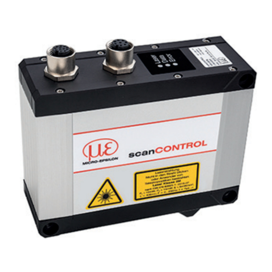
- Page 2 COMPLIES WITH 21 CFR 1040.10 AND 1040.11 EXCEPT FOR CONFORMANCE WITH Fig. 3 Sensor IEC 60825-1 ED. 3., AS DESCRIBED IN LASER NOTICE NO. 56, DATED MAY 8, 2019 LASER APERTURE with laser labels scanCONTROL 3000/BL / 3002/BL Page 2...
- Page 3 The RS422 connection (pins 11 and 12 of the multifunction port) can be used in either of the following configurations: - RS422 (half-duplex): Load user modes, sensor control and transmit measurement results (Modbus RTU or ASCII format). - Synchronization/triggering: Synchronization or triggering using switching signals scanCONTROL 3000/BL / 3002/BL Page 3...
- Page 4 SCR3000A-x 100BaseTX White (orange) Orange White (green) Blue White (blue) Green White (brown) Brown View on pin side View on solder side (ca- of male cable ble) of screw connector connector (A-coded) scanCONTROL 3000/BL / 3002/BL Page 4...
- Page 5 - 1-GHz or faster (64 bit) processor - 1 GB RAM (recommended 16 GB) - Screen resolution: 1024 x 768 (recommended 1920 x 1080) - Graphics card / GPU with OpenGL 3.1 or higher scanCONTROL 3000/BL / 3002/BL Page 5...
- Page 6 Only connect the sensor to the peripheral equipment, if it is disconnected from the power supply, i.e. only when the power supply is switched off. The sensor needs a warm-up time of typically 20 minutes for high precision measurements. scanCONTROL 3000/BL / 3002/BL Page 6...
- Page 7 - 1 PCR3000-5 multifunction cable, length 5 m; for power supply, trigger and RS422; screw connector and free cable ends - Calibration final inspection / assembly instructions - 2 Protective caps - 2 Centering elements scanCONTROL 3000/BL / 3002/BL Page 7...
- Page 8 You will find details about the individual programs in the respective operating instruc- tions or in the operating instructions of this sensor, Chap. 6.2. You will find the operating instructions online at www.micro-epsilon.com. www.micro-epsilon.com MICRO-EPSILON Messtechnik GmbH & Co. KG Koenigbacher Str.
Need help?
Do you have a question about the scanCONTROL 3000/BL and is the answer not in the manual?
Questions and answers