
Related Manuals for Edwards ModuLaser


Summary of Contents for Edwards ModuLaser
- Page 1 ModuLaser Modular Aspirating Smoke Detector Installation Manual P/N 04-4001-501-2003-08 • 01FEB19...
- Page 2 Copyright © 2019 UTC Fire & Security. All rights reserved. Trademarks and ModuLaser is a trademark of UTC Fire & Security. patents Other trade names used in this document may be trademarks or registered trademarks of the manufacturers or vendors of the respective products.
-
Page 3: Table Of Contents
Access level 4 user operation and configuration 70 Commissioning 73 Chapter 4 Maintenance and troubleshooting 79 Maintenance 80 Troubleshooting 83 Chapter 5 Technical specifications 87 Appendix A APIC installation 91 Appendix B Regulatory information 93 Index 96 ModuLaser Modular Aspirating Smoke Detector Installation Manual... -
Page 4: Important Information
Important information Introduction This is the installation and operation manual for the ModuLaser Modular Aspirating Smoke Detector. Read these instructions and all related documentation entirely before installing or operating this product. Limitation of liability To the maximum extent permitted by applicable law, in no event will UTCFS be... - Page 5 Note: Note messages advise you of the possible loss of time or effort. They describe how to avoid the loss. Notes are also used to point out important information that you should read. ModuLaser Modular Aspirating Smoke Detector Installation Manual...
- Page 6 ModuLaser Modular Aspirating Smoke Detector Installation Manual...
-
Page 7: Introduction
This chapter provides an introduction to your detector, the main controls, and the indicators. Content System overview 2 Introduction 2 Clusters 3 Connectivity 3 ClassiFire 3 Software 4 Module overview 5 Display modules 5 Detector module 7 TFT display, controls, and indicators 8 ModuLaser Modular Aspirating Smoke Detector Installation Manual... -
Page 8: System Overview
Chapter 1: Introduction System overview Introduction The ModuLaser Modular Aspirating Smoke Detector (ASD) is a highly sophisticated next generation high sensitivity smoke detection system that provides all the benefits of air sampling high sensitivity smoke detection, including very early warning. -
Page 9: Clusters
Chapter 1: Introduction Clusters Each ModuLaser high sensitivity smoke detection system consists of a group of modules known as a cluster. A cluster consists of one minimum or standard display module and from one (minimum) to eight (maximum) detector modules. -
Page 10: Software
Models and verifies the performance of the pipe network design. All pipework designs must be validated using PipeCAD. • Remote: Configures modules during installation and during system maintenance. Contact your local distributor for more details on these applications. ModuLaser Modular Aspirating Smoke Detector Installation Manual... -
Page 11: Module Overview
LED status indicators display the status of detector modules in the same cluster. The module provides connections to integrate the cluster into a SenseNET network. A PC connection is provided for configuring and monitoring the module and associated detector modules. ModuLaser Modular Aspirating Smoke Detector Installation Manual... - Page 12 The command display module is used as a central control and monitoring point for detectors in a SenseNET network. The command display module is compatible with ModuLaser clusters and legacy ASD devices compatible with SenseNET. User controls and a PC connection are provided for configuring and monitoring any device connected to the SenseNET network.
-
Page 13: Detector Module
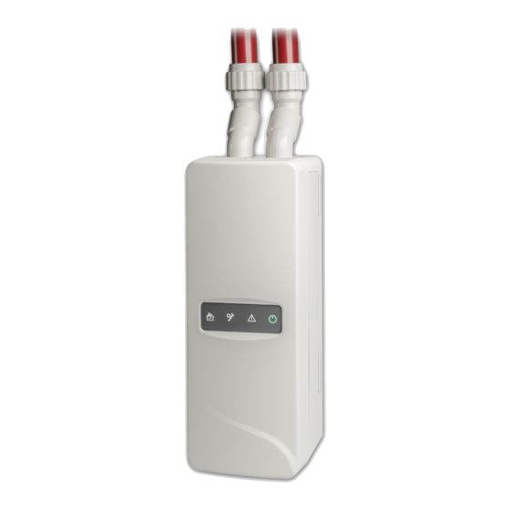
Up to eight detector modules can be connected to a minimum or standard display module to form a cluster. Figure 4: Detector module LED indicators 1. Prealarm and Fire alarm LED 3. Warning LED 2. General fault LED 4. Power LED ModuLaser Modular Aspirating Smoke Detector Installation Manual... -
Page 14: Tft Display, Controls, And Indicators
9. Navigation controls (up, down, left, right) 4. Current alarm counter 10. F1, F2, and F3 buttons (linked to F1, F2, 5. Current fault counter and F3 TFT display soft keys) 6. Current warning counter ModuLaser Modular Aspirating Smoke Detector Installation Manual... - Page 15 (minimum or standard display) or network (command display). A steady LED on a detector module indicates a general fault condition for the detector. ModuLaser Modular Aspirating Smoke Detector Installation Manual...
- Page 16 If alarms or faults are latched, then an alarm or fault indication remains active until a system reset, even if the condition that caused the indication has ended. If alarms or faults are not latched, the indication disappears when the corresponding condition ends. ModuLaser Modular Aspirating Smoke Detector Installation Manual...
-
Page 17: Installation
Content Electrical safety 12 Installation 12 Overview 12 Module and PCB layout 14 Backplane installation 17 Connections 20 Recommended cables 20 Connecting modules 21 Connecting pipes 32 Connecting to a PC 33 ModuLaser Modular Aspirating Smoke Detector Installation Manual... -
Page 18: Electrical Safety
3. Place the display or detector module (without the cover) onto the backplane. See “Installing the display and detector modules” on page 31. 4. Install piping. See “Connecting pipes” on page 32. 5. Place the front cover onto the display or detector module. ModuLaser Modular Aspirating Smoke Detector Installation Manual... - Page 19 DO set the module addresses correctly to avoid duplicate addresses. DO ensure that the display and detector modules are secured to the backplane. DO ensure that all front covers are secured to the modules. ModuLaser Modular Aspirating Smoke Detector Installation Manual...
-
Page 20: Module And Pcb Layout
12. SenseNET+ connectors for bus or loop 6. J5 SenseNET+ connector for adjacent configuration backplanes 13. Rear cable knockouts 7. I/P2 input connector Note: The SenseNET and APIC connectors are only used in display modules. ModuLaser Modular Aspirating Smoke Detector Installation Manual... - Page 21 1. USB type A connector 4. Ethernet connector (see note below) 2. RJ11 connector (see note below) 5. Cover sensor 3. USB type B connector Note: RJ11 and Ethernet connections are not supported at this time. ModuLaser Modular Aspirating Smoke Detector Installation Manual...
- Page 22 The detector module may also be installed onto the backplane at 180 degrees to enable pipe entry from below (as shown on the right in Figure 8 above). There is no change to the installation orientation of the backplane. ModuLaser Modular Aspirating Smoke Detector Installation Manual...
-
Page 23: Backplane Installation
3. Using a screwdriver, push both of the locking clips up to lock the unit to the rail. Figure 9: Installing the backplane onto a DIN rail 1. Backplane (rear view) 4. Backplane (front view) 2. Mounting hooks 5. Locking clips 3. DIN rail ModuLaser Modular Aspirating Smoke Detector Installation Manual... - Page 24 5. Remove the backplane from the wall, and then drill and plug the remaining fixing holes 6. Replace the backplane, check alignment, and then tighten all fixing screws. Figure 10: Installing the backplane onto a wall 1. Keyhole screw slot 2. Holding screw slots ModuLaser Modular Aspirating Smoke Detector Installation Manual...
- Page 25 Figure 11 above (this needs to be done before the backplane is installed onto the wall). ModuLaser Modular Aspirating Smoke Detector Installation Manual...
-
Page 26: Connections
Securing cables Use cable glands to ensure clean and secure connections. All cables should be fed through the cable knockouts on the top, bottom, or back of the housing and secured to eliminate movement. ModuLaser Modular Aspirating Smoke Detector Installation Manual... -
Page 27: Connecting Modules
Chapter 2: Installation Connecting modules Connector overview Figure 12: Backplane PCB connectors (top) Figure 13: Backplane PCB connectors (bottom) ModuLaser Modular Aspirating Smoke Detector Installation Manual... - Page 28 Power supply (positive) [1] If used, end-of-line termination is required for the unused J3 connector. [2] If used, end-of-line termination is required for the unused J5 connector. [3] Used for connecting an addressable loop. ModuLaser Modular Aspirating Smoke Detector Installation Manual...
- Page 29 (see “Connecting the power supply” on page 26). Figure 14: Non-distributed cluster 1. Ribbon cable Note: End-of-line termination is not required for unused J3 and J5 connectors in this cluster type. ModuLaser Modular Aspirating Smoke Detector Installation Manual...
- Page 30 26) and an end-of-line termination to be installed onto the unused J3 and J5 connectors on the backplane PCB. Figure 15: Distributed cluster 1. End-of-line termination (required for all unused J3 and J5 connectors in this cluster type) ModuLaser Modular Aspirating Smoke Detector Installation Manual...
- Page 31 J3 and J5 connectors on the backplane PCB. Figure 16: Hybrid cluster 1. SenseNET+ connections 2. Ribbon cables 3. End-of-line termination (required for all unused J3 and J5 connectors in this cluster type) ModuLaser Modular Aspirating Smoke Detector Installation Manual...
- Page 32 See “Connecting a non-distributed cluster” on page 23, “Connecting a distributed cluster” on page 24, and “Connecting a hybrid cluster” on page 25 for more information on power supply requirements for each type of cluster. ModuLaser Modular Aspirating Smoke Detector Installation Manual...
- Page 33 – see “Using a secondary command module” on page 68. Note: The SenseNET network is a communications loop based on the RS-485 master-slave protocol. This allows you to manage and monitor up to 127 modules (displays and detectors). ModuLaser Modular Aspirating Smoke Detector Installation Manual...
- Page 34 Figure 17: Connecting a multiple cluster network 1. Minimum display module (first cluster) 2. Command display module (stand-alone) 3. Standard display module (second cluster) Note: The network configuration may also be closed to provide for redundancy within the network. ModuLaser Modular Aspirating Smoke Detector Installation Manual...
- Page 35 APIC connector on the backplane PCB (display modules only), the detection system becomes an additional device on the addressable loop. See Appendix A “APIC installation” on page 91 for more information on installing an APIC board. ModuLaser Modular Aspirating Smoke Detector Installation Manual...
- Page 36 (including command modules) and is set using the first seven bits of the DIP switch (bit 8 is not used). The full range of addresses and their settings is shown in Figure 18 below. Figure 18: Address settings 1. DIP switch setting 2. Address ModuLaser Modular Aspirating Smoke Detector Installation Manual...
- Page 37 There is no change to the installation orientation of the backplane. Figure 19: Installing the display and detector modules ModuLaser Modular Aspirating Smoke Detector Installation Manual...
-
Page 38: Connecting Pipes
Figure 20: Connecting pipes using a pipe adaptor 1. Pipe 5. Internal view of 20 to 25 mm gap 2. Rubber seal 6. Exhaust pipe 3. Nut 7. Sampling pipe (inlet) 4. Offset adaptor 8. Detector ModuLaser Modular Aspirating Smoke Detector Installation Manual... -
Page 39: Connecting To A Pc
If using the Remote software application, connect a PC to the USB type B connector on the display module (see Figure 7 on page 15). Note: The USB type B connector may only be used for temporary connections. ModuLaser Modular Aspirating Smoke Detector Installation Manual... - Page 40 Chapter 2: Installation ModuLaser Modular Aspirating Smoke Detector Installation Manual...
-
Page 41: Configuration And Commissioning
Access level 3 user operation and configuration 53 The Main menu 54 General Settings menu 54 The Device Settings menu 55 The Detection Settings menu 62 The Communications menu 67 The Log menu 69 ModuLaser Modular Aspirating Smoke Detector Installation Manual... -
Page 42: Introduction
Use the up and down arrows to select the number, and then press the right arrow to confirm the entry and move to the next number. When a valid four-digit access code has been entered, the display shows the Main menu for the selected access level. ModuLaser Modular Aspirating Smoke Detector Installation Manual... -
Page 43: Configuration Overview
Main menu or the submenu to apply the changes to the system. Configuration overview Note: Configuration options provided in this manual are for the ModuLaser system only and may differ from legacy ASD units. Configuration methods The detection system can be configured using the display module controls or via a PC. - Page 44 Soft key – functionality changes depending on menu (Menu, Logout, Exit, etc.) Soft key – functionality changes depending on menu (Menu, Logout, Exit, etc.) Soft key – functionality changes depending on menu (Menu, Logout, Exit, etc.) ModuLaser Modular Aspirating Smoke Detector Installation Manual...
-
Page 45: Wizards
3. Press F3 (Next) to step through the menus included in the wizard (see Table 9 on page 40). Press Enter to access a menu. From a menu, press F2 (Back) to return to the wizard. ModuLaser Modular Aspirating Smoke Detector Installation Manual... - Page 46 Configure flow limit values, fan speed, and power save settings for detectors See “Configuring flow parameters” on page 66 for more information. Inputs Configure input settings See “Configuring the inputs” on page 56 for more information. ModuLaser Modular Aspirating Smoke Detector Installation Manual...
-
Page 47: Access Level 1 User Operation
Configure screen properties (brightness, backlight mode, timeout, power save, etc.) • View or save event logs and chart records • Perform tests (installation, inputs, outputs, user interface, etc.) • Reset the system • Enable and disable devices and configurable options ModuLaser Modular Aspirating Smoke Detector Installation Manual... -
Page 48: Detector Status
Detector online Indicates that the detector is online. Detector offline Indicates that the detector is offline. Detector disabled Indicates that the detector is disabled. Detector in test Indicates that the detector is in test. ModuLaser Modular Aspirating Smoke Detector Installation Manual... - Page 49 Alarm 2 [2] Displays during a Fire Alarm 2 state Alarm [2] Displays during a Fire Alarm state Prealarm [2] Displays during a Prealarm state Alert [2] Displays during an Alert/Aux. Alarm state ModuLaser Modular Aspirating Smoke Detector Installation Manual...
-
Page 50: The Main Menu
Table 14: Localization options Option Description Language Configures the language of the display, and log files. Units Configures the measurement unit system (metric or imperial). Date Format Configures the date format (DD/MM/YY or MM/DD/YY). ModuLaser Modular Aspirating Smoke Detector Installation Manual... - Page 51 90 seconds of inactivity when a mains fault is detected. [1] For access levels 1 and 2, backlight brightness is reduced after half of the configured timeout value. ModuLaser Modular Aspirating Smoke Detector Installation Manual...
-
Page 52: The Device Settings Menu
To view the baseline comparison: 1. Select Device Settings from the Main menu, and then select Detection Settings. 2. Select Baseline, and then select View Baseline. A list of detectors is displayed. ModuLaser Modular Aspirating Smoke Detector Installation Manual... -
Page 53: The Communications Menu
To save an event log: 1. Remove the display cover, insert a USB flash drive into the USB connector, and replace the cover. 2. Select Log from the Main menu, and then select Save Event Log. ModuLaser Modular Aspirating Smoke Detector Installation Manual... - Page 54 2. Select Log from the Main menu, and then select Save Chart Record. 3. Select the detector that you want to view or press F1 (Go To) to search for a detector by the device address. ModuLaser Modular Aspirating Smoke Detector Installation Manual...
-
Page 55: The Test Menu
Performing an installation test The installation test is used to test fire detection and notification. When this test mode is active: • General fault outputs are activated • Fire outputs are not activated ModuLaser Modular Aspirating Smoke Detector Installation Manual... - Page 56 4. Press F2 (Cancel) to end the test. Note: Return the input to its default state before ending the test. If not, any configured input functionality may be activated when the test ends. ModuLaser Modular Aspirating Smoke Detector Installation Manual...
- Page 57 The test status is displayed as Running (test in progress) or No test (test not supported by this device type). Once the test has been completed, it will indicate Pass or Fail. 3. Press F3 (Exit) to return to the Main menu. ModuLaser Modular Aspirating Smoke Detector Installation Manual...
-
Page 58: The Reset Menu
For example, faults and alarms are detected but are not indicated (they are added to the event log). Note: When a detector is disabled, the detector Warning LED is steady and the disablement is confirmed on the display module LCD. ModuLaser Modular Aspirating Smoke Detector Installation Manual... -
Page 59: Access Level 3 User Operation And Configuration
41, this level lets you: • Configure the date and time. • Configure the device settings (inputs, outputs, etc.) • Configure the detection settings (alarm levels, delays, flow, etc.) • Configure the communications settings (network setup, etc.) ModuLaser Modular Aspirating Smoke Detector Installation Manual... -
Page 60: The Main Menu
To change the date format, select General Settings from the Main menu, and then select Localization. 3. Press F1 (Set) to save your changes and exit to the previous screen. ModuLaser Modular Aspirating Smoke Detector Installation Manual... -
Page 61: The Device Settings Menu
4. Press F1 (Save) to save your changes and exit to the previous screen. 5. If you have no other configuration changes to make, then press F1 (Apply) from the Main menu or the submenu to apply the changes to the system. ModuLaser Modular Aspirating Smoke Detector Installation Manual... - Page 62 Local only affects the local device (this is the default setting). Cluster applies the configured input functionality to all modules in the cluster. Function Configures the functionality. See Table 20 on page 57 for more information. ModuLaser Modular Aspirating Smoke Detector Installation Manual...
- Page 63 Avoid configuring two or more inputs with the same functionality (this may create conflicts). • Inputs and input functionality for legacy devices may vary from those described here. Refer to the corresponding device installation manual for more information. ModuLaser Modular Aspirating Smoke Detector Installation Manual...
- Page 64 4. Press F1 (Save) to save your changes and exit to the previous screen. 5. If you have no other configuration changes to make, then press F1 (Apply) from the Main menu or the submenu to apply the changes to the system. ModuLaser Modular Aspirating Smoke Detector Installation Manual...
- Page 65 The output activates when the applicable device or devices are in any Warning state. Disable The output activates when the applicable device or devices are disabled. Test The output activates when the applicable device or devices are in any Test state. ModuLaser Modular Aspirating Smoke Detector Installation Manual...
- Page 66 Where AAA is the device address, YYYYMMDD is the current date, HHMM is the current time, and TT is a the device type identification code. 5. Press F3 (Exit) to return to the Main menu. ModuLaser Modular Aspirating Smoke Detector Installation Manual...
- Page 67 2. Select All Devices or List of Devices. Selecting All Devices restores all modules on the loop. Selecting List of Devices allows you to select specific modules to restore. 3. Press Enter to restore the selected devices. ModuLaser Modular Aspirating Smoke Detector Installation Manual...
-
Page 68: The Detection Settings Menu
[1] The working alarm factor value may be higher than the configured value as the ClassiFire algorithm automatically adjusts the value based on the environmental conditions at the end of the FastLearn procedure. ModuLaser Modular Aspirating Smoke Detector Installation Manual... - Page 69 [1] The Fire Alarm delay countdown may start after the Prealarm countdown elapses if Cascading Alarms is enabled (in the Alarm Levels menu). [2] This option has priority over Cascading Alarms configuration. ModuLaser Modular Aspirating Smoke Detector Installation Manual...
- Page 70 4. Press F1 (Save) to save your changes and exit to the previous screen. 5. If you have no other configuration changes to make, then press F1 (Apply) from the Main menu or the submenu to apply the changes to the system. ModuLaser Modular Aspirating Smoke Detector Installation Manual...
- Page 71 4. Press F1 (Save) to save your changes and exit to the previous screen. 5. If you have no other configuration changes to make, then press F1 (Apply) from the Main menu or the submenu to apply the changes to the system. ModuLaser Modular Aspirating Smoke Detector Installation Manual...
- Page 72 3. Select Start Pipe Calibration, and then press Enter. Pipe calibration takes approximately 60 minutes and the remaining time is displayed on the detector status screen (see “Detector status” on page 42). The detector system operates normally during pipe calibration. ModuLaser Modular Aspirating Smoke Detector Installation Manual...
-
Page 73: The Communications Menu
SN Looped Bus [1] Configures the SenseNET loop protocol. If checked, the network uses a Class A closed loop topology. ModuLaser Modular Aspirating Smoke Detector Installation Manual... - Page 74 If the primary command module is recovered, then the secondary module returns to listening mode. • The primary command module configures the secondary command module remotely. It appears in the device list after a network scan. ModuLaser Modular Aspirating Smoke Detector Installation Manual...
-
Page 75: The Log Menu
2. Select Clear Chart Record. 3. Select the device that you want to view or press F1 (Go To) to search for a device by the device address. 4. Press OK to confirm the operation. ModuLaser Modular Aspirating Smoke Detector Installation Manual... -
Page 76: Access Level 4 User Operation And Configuration
53, this level lets you: • Upgrade device firmware • Customize or restore device logos The Main menu The Main menu for this access level is shown below. Figure 25: Access level 4 Main menu ModuLaser Modular Aspirating Smoke Detector Installation Manual... -
Page 77: The General Settings Menu
3. Select the device that you want to view or press F1 (Go To) to search for a device by the device address. 4. Press OK to confirm the operation. Press exit to view the home screen. The default logo is displayed if there are no active events. ModuLaser Modular Aspirating Smoke Detector Installation Manual... -
Page 78: The Device Settings Menu
The upgrade procedure may take a long time to complete. If necessary, press Cancel to safely abort the upgrade. 6. After completion, follow the onscreen instructions to restart the system. ModuLaser Modular Aspirating Smoke Detector Installation Manual... -
Page 79: Commissioning
• Check all electrical wiring and connections. • Check that power supplies are sufficient for the installation and that they provide the required battery standby period. ModuLaser Modular Aspirating Smoke Detector Installation Manual... -
Page 80: Configuration Check
FastLearn starts automatically if the detector is new (or restarting) and if Auto FastLearn is enabled. The FastLearn process lasts approximately 15 minutes and is followed by approximately 24 hours of intermediate learning (if Demo mode is not enabled). ModuLaser Modular Aspirating Smoke Detector Installation Manual... - Page 81 Smoke pellet tests for Class C installations Use of canned smoke is not recommended to test the detector as the particles don't last long enough to travel the full length of the sampling pipe. ModuLaser Modular Aspirating Smoke Detector Installation Manual...
- Page 82 After this period most of the insulation should be burned off. Notes: The wire cross-section should be AWG 10 with the following diameter and area: • Diameter 2.59 mm (0.10189 in.) • Cross-section area 5.0 mm² (0.00775 in.²) ModuLaser Modular Aspirating Smoke Detector Installation Manual...
-
Page 83: Connectivity Check
Ensure that communications between the detector and any fire control and indicating equipment (especially alarm and fault conditions) operate correctly. Check any other cause and effect requirements, particularly in relation to integration with automatic suppression systems. ModuLaser Modular Aspirating Smoke Detector Installation Manual... - Page 84 Chapter 3: Configuration and Commissioning ModuLaser Modular Aspirating Smoke Detector Installation Manual...
-
Page 85: Maintenance And Troubleshooting
Chapter 4 Maintenance and troubleshooting Summary This chapter provides maintenance and troubleshooting procedures. Content Maintenance 80 Troubleshooting 83 ModuLaser Modular Aspirating Smoke Detector Installation Manual... -
Page 86: Maintenance
– contact your local supplier for more information and to arrange servicing. Also take precautions to avoid or limit any future contamination. ModuLaser Modular Aspirating Smoke Detector Installation Manual... - Page 87 It is recommended that suitable masks and protective clothing be worn when changing filters. Maintenance work must be performed in compliance with national and/or regional requirements and other applicable standards. ModuLaser Modular Aspirating Smoke Detector Installation Manual...
- Page 88 Figure 26. Slide the entire assembly into the detector and make sure the cartridge is correctly installed. 5. Secure the filter assembly using a screw. Figure 26: Replacing the dust filter 1. Detector 2. Dust filter 3. Plastic cover ModuLaser Modular Aspirating Smoke Detector Installation Manual...
-
Page 89: Troubleshooting
In this case, it would be necessary to lead a pipe from the exhaust to the protected area to ensure nominal flow. ModuLaser Modular Aspirating Smoke Detector Installation Manual... - Page 90 Network Loop Break The network loop is not closed and Looped Bus is configured Fault Invalid Address Invalid address assigned to device Fault Multiple Cluster More than one display module found in the cluster Displays ModuLaser Modular Aspirating Smoke Detector Installation Manual...
- Page 91 FastLearn in progress Warning Power Save Mode Power Save mode enabled Warning Flow Low Range Flow below absolute low range Warning Flow High Range Flow below absolute high range Warning Demo Mode Demo Mode enabled ModuLaser Modular Aspirating Smoke Detector Installation Manual...
- Page 92 Warning Detector Replaced A cluster detector has been replaced (reset the module to remove the warning) Warning Flow Setup Started Detector in Flow Startup mode Warning Pipe Calibration Detector in Pipe Calibration mode ModuLaser Modular Aspirating Smoke Detector Installation Manual...
-
Page 93: Technical Specifications
Inputs and outputs Inputs Number of inputs 15 KΩ 5% 1/4 W End-of-line resistance Outputs Number of outputs Contact type C/NO/NC, voltage free Resistive load 2 A at 30 VDC ModuLaser Modular Aspirating Smoke Detector Installation Manual... - Page 94 Average sound pressure level 38.8 dBA (fan speed 6) Chart record From 1 month at 1 s resolution up to 5 years at 60 s resolution per detector module Event log 20,000 events per module ModuLaser Modular Aspirating Smoke Detector Installation Manual...
- Page 95 −20ºC to +60ºC (0ºC to 38ºC UL268, cUL Operating temperature and FM) −20ºC to +60ºC Storage temperature Relative humidity +5 to 95% noncondensing (0 to 90% for UL/cUL and FM) IEC 61010-1 Pollution degree 1 IEC 61010-1 Installation Cat. II ModuLaser Modular Aspirating Smoke Detector Installation Manual...
- Page 96 Chapter 5: Technical specifications ModuLaser Modular Aspirating Smoke Detector Installation Manual...
-
Page 97: Appendix Aapic Installation
WARNING: To ensure compatibility, only install the Apollo APIC (9-30430) in your ModuLaser display module. Incompatible APIC and fire alarm control panel combinations can result in a non-operational system that may fail to perform during an alarm event, with resultant loss of life and/or property. - Page 98 Appendix A: APIC installation Figure 27: APIC installation 1. APIC board 4. Holding clips 2. APIC ribbon cable 5. J501 connector 3. Alignment stud ModuLaser Modular Aspirating Smoke Detector Installation Manual...
-
Page 99: Appendix B Regulatory Information
See the product Declaration of Performance Declared performance See the product Declaration of Performance [1] When used with a compatible display or detector module. See “EN 54-20 compliance” on page 94 for more information. ModuLaser Modular Aspirating Smoke Detector Installation Manual... - Page 100 All modules must be powered by a suitable power supply approved to EN 54-4. • All cable glands must be rated IP67 or higher. For more information on PipeCAD, see your PipeCAD documentation. ModuLaser Modular Aspirating Smoke Detector Installation Manual...
- Page 101 These products have been designed in accordance with the following European standards for electrical safety and electromagnetic compatibility: • EN 60950-1 • EN 50130-4 • EN 61000-6-3 • EN 61000-3-2 • EN 61000-3-3 ModuLaser Modular Aspirating Smoke Detector Installation Manual...
-
Page 102: Index
84 firmware upgrade, 72 inputs, 56 network setup, 67 flow setup menu, 66 outputs, 58 restore cluster configuration, 61 restore default logo, 71 restore default settings, 61 saving, loading files, 60 ModuLaser Modular Aspirating Smoke Detector Installation Manual... - Page 103 1 user, 41 access level 2 user, 41 access level 3 user, 53 access level 4 user, 70 output configuration, 58 connections, 26 test, 50 reset, 52 software applications, 4 ModuLaser Modular Aspirating Smoke Detector Installation Manual...
Need help?
Do you have a question about the ModuLaser and is the answer not in the manual?
Questions and answers
does a system smoke detector require a box or can I mount it with just a ring
The Edwards ModuLaser system requires a backplane to be fixed to the wall for installation. The detector and display modules are then mounted onto this backplane. This suggests that a simple ring mount is not sufficient for installation.
This answer is automatically generated