Advertisement
Quick Links
INSTALLATION AND MAINTENANCE INSTRUCTIONS
EDW2151A Low Profile
Photoelectronic Plug-in
Smoke Detector
Specifications
Size
Height:
Diameter:
Weight:
Operating Temperature Range:
Operating Humidity Range:
Operating Voltage
Standby Current
Latching Alarm:
Before Installing
Please thoroughly read the manual A05-1003, Applica-
tions Guide for System Smoke Detectors, which provides
detailed information on detector spacing, placement, zon-
ing, wiring, and special applications. Copies of this manual
are available from Edwards.
NOTICE: This manual should be left with the owner/user
of this equipment.
IMPORTANT: The detector must be tested and maintained
regularly following CAN/ULC S536 requirements. The de-
tector should be cleaned at least once a year.
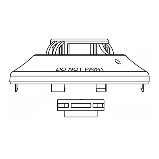
General Description
The EDW2151A low-profile photoelectronic detector uses
a state-of-the-art optical sensing chamber. This detector is
designed to provide open area protection and to be used
with compatible ULC listed control panels only. The ca-
pability of plugging this detector into a variety of special
bases makes it more versatile than equivalent direct-wired
models.
Two LEDs on each detector provide local 360° visible
alarm indication. They flash every five seconds indicating
that power is applied and the detector is working properly.
The LEDs latch on in alarm. Remote LED annunciator ca-
pability is standard and may be implemented through an
optional accessory RA100ZA. The alarm can be reset only
by a momentary power interruption. This detector may be
tested by activating the internal reed switch with a magnet,
or by using the CSENS-RDRA infrared sensitivity reader.
Base Selection And Wiring Guide
Refer to the installation instructions for the Plug-in Detector
Bases for base selection and wiring instructions. Edwards
has a variety of detector bases available for this smoke
detector, including 2-wire applications with and without re-
lays and/or current limiting resistors, 4-wire and 120VAC
D100-101-00
2.0 inches (51 mm) installed in B401A Base
4.1 inches (104 mm) installed in B401A Base
6.1 inches (155 mm) installed in B110LPA Base
3.1 oz. (88 g)
0°C to 49°C (32°F to 120°F)
10% to 93% Relative Humidity noncondensing
8.5 to 35VDC
120 uA
Reset by momentary power interruption.
applications.
All bases are provided with screw terminals for power,
ground, remote annunciator connections and relay contact
connections, if applicable. The electrical ratings for each
detector-base combination are also included in the base
installation instructions.
Installation
Installation shall comply with the latest version of CAN/
ULC S524, Installation of Fire Alarm Systems.
NOTE: All wiring must conform to applicable local codes,
ordinances, and regulations.
NOTE: Verify that all detector bases are installed, that
the initiating-device circuits have been tested, and that
the wiring is correct. (Refer to detector base manual for
testing procedure.)
Remove power from initiating-device circuits before install-
ing detectors.
1. Install detectors:
2. Tamper Resistance: The detector bases can be made
3. After all detectors have been installed, apply power to
1
625 6th Street East, Owen Sound, Ontario N4K-5P8
TEL:519-376-2430, FAX: 519-376-1296
WARNING
a. Place the detector into the detector base.
b. Turn the detector clockwise until the detector drops
into place.
c. Continue turning detector clockwise to lock it in place.
tamper resistant. When capability is enabled, detectors
cannot be removed from the base without the use of a
tool. See the detector base installation manual of the
detector base for details in using this capability.
I56-1580-000
Advertisement

Related Manuals for Edwards EST EDW2151A


Summary of Contents for Edwards EST EDW2151A
-
Page 1: Smoke Detector
Refer to the installation instructions for the Plug-in Detector tool. See the detector base installation manual of the Bases for base selection and wiring instructions. Edwards detector base for details in using this capability. has a variety of detector bases available for this smoke 3. - Page 2 CSENS-RDRA instruction manual for operating details. may not completely prevent airborne dust particles from B. Aerosol Generator (Gemini 501) entering the detector. Therefore, Edwards recommends Set the generator to represent 4% to 5%/ft. obscura- the removal of detectors before beginning construction or tion as described in the Gemini 501 Manual.
- Page 3 Figure 2: 1. Remove the sensor to be cleaned from the system. 2. Remove the sensor cover by pressing firmly on each of the four removal tabs that hold the cover in place. 3. Vacuum the screen carefully without removing it. If further cleaning is required continue with Step 4, oth- Sensor Cover...
- Page 4 Please refer to insert for the Limitations of Fire Alarm Systems D100-101-00 I56-1580-000 ©2015 Edwards...
Need help?
Do you have a question about the EST EDW2151A and is the answer not in the manual?
Questions and answers