
Subscribe to Our Youtube Channel
Related Manuals for WAGO 750-438


Summary of Contents for WAGO 750-438
- Page 1 Manual WAGO-I/O-SYSTEM 750 2DI NAMUR Ex i 750-438 2-Channel Digital Input Module NAMUR, Ex i, Proximity sensor acc. to DIN EN 50227 V 1.2.0...
- Page 2 WAGO-I/O-SYSTEM 750 750-438 2DI NAMUR Ex i © 2013 by WAGO Kontakttechnik GmbH & Co. KG All rights reserved. WAGO Kontakttechnik GmbH & Co. KG Hansastraße 27 D-32423 Minden Phone: +49 (0) 571/8 87 – 0 Fax: +49 (0) 571/8 87 – 1 69 E-Mail: info@wago.com...
-
Page 3: Table Of Contents
WAGO-I/O-SYSTEM 750 Table of Contents 750-438 2DI NAMUR Ex i Table of Contents Table of Contents ....................3 Notes about this Documentation ..............5 Validity of this Documentation ..............5 Copyright ....................5 Symbols ..................... 6 Number Notation ..................8 Font Conventions .................. - Page 4 Table of Contents WAGO-I/O-SYSTEM 750 750-438 2DI NAMUR Ex i 7.1.2 Marking for America according to NEC 500 ........39 Installation Regulations ................40 7.2.1 Special conditions for safe use (ATEX Certificate TÜV 07 ATEX 554086 X) ................... 41 7.2.2 Special conditions for safe use (ATEX Certificate TÜV 12 ATEX...
-
Page 5: Notes About This Documentation
This documentation is only applicable to the I/O module 750-438 (2DI NAMUR Ex i) of the WAGO-I/O-SYSTEM 750 series. The I/O module 750-438 shall only be installed and operated according to the instructions in this manual and in the manual for the used fieldbus coupler/controller. -
Page 6: Symbols
Notes about this Documentation WAGO-I/O-SYSTEM 750 750-438 2DI NAMUR Ex i Symbols Personal Injury! Indicates a high-risk, imminently hazardous situation which, if not avoided, will result in death or serious injury. Personal Injury Caused by Electric Current! Indicates a high-risk, imminently hazardous situation which, if not avoided, will result in death or serious injury. - Page 7 WAGO-I/O-SYSTEM 750 Notes about this Documentation 750-438 2DI NAMUR Ex i Additional Information: Refers to additional information which is not an integral part of this documentation (e.g., the Internet). Manual V 1.2.0...
-
Page 8: Number Notation
Notes about this Documentation WAGO-I/O-SYSTEM 750 750-438 2DI NAMUR Ex i Number Notation Table 1: Number notation Number code Example Note Decimal Normal notation Hexadecimal 0x64 C notation Binary '100' In quotation marks, nibble separated with '0110.0100' dots (.) Font Conventions... -
Page 9: Important Notes
2.1.1 Subject to Changes WAGO Kontakttechnik GmbH & Co. KG reserves the right to provide for any alterations or modifications that serve to increase the efficiency of technical progress. WAGO Kontakttechnik GmbH & Co. KG owns all rights arising from the granting of patents or from the legal protection of utility patents. -
Page 10: Technical Condition Of Specified Devices
The components to be supplied Ex Works, are equipped with hardware and software configurations, which meet the individual application requirements. WAGO Kontakttechnik GmbH & Co. KG will be exempted from any liability in case of changes in hardware or software as well as to non-compliant usage of components. -
Page 11: Safety Advice (Precautions)
Installation only in appropriate housings, cabinets or in electrical operation rooms! The WAGO-I/O-SYSTEM 750 and its components are an open system. As such, install the system and its components exclusively in appropriate housings, cabinets or in electrical operation rooms. Allow access to such equipment and fixtures to authorized, qualified staff only by means of specific keys or tools. - Page 12 Important Notes WAGO-I/O-SYSTEM 750 750-438 2DI NAMUR Ex i Do not use any contact spray! Do not use any contact spray. The spray may impair contact area functionality in connection with contamination. Do not reverse the polarity of connection lines! Avoid reverse polarity of data and power supply lines, as this may damage the devices involved.
-
Page 13: Device Description
Device Description 750-438 2DI NAMUR Ex i Device Description The digital input module 750-438 receives binary signals from sensors operating in hazardous environments of zones 0 or 1, e.g. NAMUR sensors, optocouplers, mechanical contacts or other actuating elements. Installation only in zone 2 or in non-hazardous environments! The installation of the WAGO-I/O-SYSTEM 750 fieldbus couplers/controllers and I/O modules is only to be done in zone 2 or in non-hazardous environments. -
Page 14: Figure 1: Supply Principle Ex I
Device Description WAGO-I/O-SYSTEM 750 750-438 2DI NAMUR Ex i Figure 1: Supply principle Ex i The Ex i I/O module receives the 24V voltage supply for the field level from an upstream Ex i I/O module or from an Ex i power supply module via the power contacts used as blade contacts. - Page 15 Any configuration of the I/O module is possible within an intrinsically safe segment when configuring the fieldbus node. An arrangement in groups within the group of potentials is not necessary. The I/O module 750-438 can be used with all fieldbus couplers/controllers of the WAGO-I/O-SYSTEM 750. Further information about explosion prevention! Further information about explosion prevention can be found in section "Use in...
-
Page 16: View
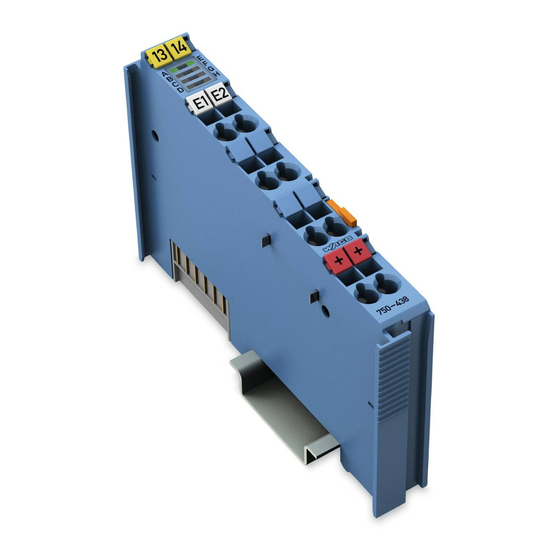
Device Description WAGO-I/O-SYSTEM 750 750-438 2DI NAMUR Ex i View Figure 2: View Table 3: Caption acc. to figure “View “ Designation Description Details see chapter Marking possibility with Mini-WSB „Device description“ > A, E Status-LEDs „Display elements“ „Assembly“ > „Mounting Data contacts device“... -
Page 17: Connectors
WAGO-I/O-SYSTEM 750 Device Description 750-438 2DI NAMUR Ex i Connectors 3.2.1 Data Contacts/Internal Bus Communication between the coupler/controller and the I/O modules as well as the system supply of the I/O modules is carried out via the internal bus. It is comprised of 6 data contacts, which are available as self-cleaning gold spring contacts. -
Page 18: Power Jumper Contacts/Field Supply
The male contacts are sharp-edged. Handle the module carefully to prevent injury. The I/O module 750-438 has 2 self-cleaning power jumper contacts that supply and transmit power for the field side. The contacts on the left side of the I/O module are designed as male contacts and the contacts on the right side as spring contacts. -
Page 19: Cage Clamp
WAGO-I/O-SYSTEM 750 Device Description 750-438 2DI NAMUR Ex i ® 3.2.3 CAGE CLAMP Connections Table 5: Connections Chann Connection Designation Function DI 1 Input DI 1: Signal voltage Uv 1 Input DI 1: Sensor supply DI 2 Input DI 2: Signal voltage... -
Page 20: Display Elements
Input DI 1: Signal voltage (1) Figure 6: Display Input DI 2: Signal voltage (0) elements State DI 2 green Input DI 2: Signal voltage (1) Operating Elements The I/O module 750-438 has no operating elements. Manual V 1.2.0... -
Page 21: Schematic Diagram
WAGO-I/O-SYSTEM 750 Device Description 750-438 2DI NAMUR Ex i Schematic Diagram Figure 7: Schematic diagram Manual V 1.2.0... -
Page 22: Technical Data
Device Description WAGO-I/O-SYSTEM 750 750-438 2DI NAMUR Ex i Technical Data 3.6.1 Device data Table 7: Technical data device Wide 12 mm Height (from upper edge of 35 DIN rail) 64 mm Depth 100 mm Weight ca. 46.9 g 3.6.2... -
Page 23: Inputs
WAGO-I/O-SYSTEM 750 Device Description 750-438 2DI NAMUR Ex i 3.6.4 Inputs Table 4: Technical data Inputs No. of inputs ≤ 1.2 mA Signal current (0) ≥ 2.1 mA Signal current (1) Switching hysteresis 0.2 mA Input filter 3 ms ≥ 5 ms Input pulse duration ≥... -
Page 24: Explosion Protection
Device Description WAGO-I/O-SYSTEM 750 750-438 2DI NAMUR Ex i 3.6.5 Explosion Protection Table 5: Technical data Explosion Protection Ex directive 94/9/EG EN 60079-0:2006, EN 60079-11:2007, EN 60079-15:2005, EN 61241-0:2006, EN 61241-1:2004, EN61241-11:2006 Safety Data electric circuit = 12 V = 13.5 mA = 40.5 mW... -
Page 25: Approvals
≤ +60 °C Ambient temperature range: ANSI/ISA 12.12.01 Class I, Div2 ABCD T4 The following ship approvals have been granted to the basic version of 750-438 I/O modules: ABS (American Bureau of Shipping) Federal Maritime and Hydrographic Agency BV (Bureau Veritas) Manual V 1.2.0... -
Page 26: Standards And Guidelines
Env. 1, 2, 3, 4 NKK (Nippon Kaiji Kyokai) PRS (Polski Rejestr Statków) RINA (Registro Italiano Navale) Standards and Guidelines 750-438 I/O modules meet the following requirements on emission and immunity of interference: EC EMC Directive 2004/108/EC EMC CE-Emission of interference acc. -
Page 27: Mounting
Don't forget the end module! Always plug an end module 750-600 onto the end of the fieldbus node! You must always use an end module at all fieldbus nodes with the WAGO I/O System 750 fieldbus couplers/controllers to guarantee proper data transfer. -
Page 28: Inserting And Removing Devices
Mounting WAGO-I/O-SYSTEM 750 750-438 2DI NAMUR Ex i Inserting and Removing Devices Use caution when interrupting the PE! Make sure that people or equipment are not placed at risk when removing an I/O module and the associated PE interruption. To prevent interruptions, provide ring feeding of the ground conductor, see section "Grounding/Ground Conductor"... -
Page 29: Removing The I/O Module
WAGO-I/O-SYSTEM 750 Mounting 750-438 2DI NAMUR Ex i With the I/O module snapped in place, the electrical connections for the data contacts and power contacts (if any) to the fieldbus coupler/controller or to the previous or possibly subsequent I/O module are established. -
Page 30: Connect Devices
Do not connect more than one conductor at one single connection! If more than one conductor must be routed to one connection, these must be connected in an up-circuit wiring assembly, for example using WAGO feed- through terminals. Exception: If it is unavoidable to jointly connect 2 conductors, then you must use a ferrule to join the wires together. -
Page 31: Connection Example
WAGO-I/O-SYSTEM 750 Connect Devices 750-438 2DI NAMUR Ex i Connection Example Figure 1: Connecting diagram Manual V 1.2.0... -
Page 32: Process Image
Process Image WAGO-I/O-SYSTEM 750 750-438 2DI NAMUR Ex i Process Image Mapping of process data in the process image of fieldbus systems The representation of the process data of some I/O modules or their variations in the process image depends on the fieldbus coupler/controller used. Please take this information from the section "Fieldbus Specific Design of the Process Data"... -
Page 33: Use In Hazardous Environments
Use in Hazardous Environments 750-438 2DI NAMUR Ex i Use in Hazardous Environments The WAGO-I/O-SYSTEM 750 (electrical equipment) is designed for use in Zone 2 hazardous areas. The following sections include both the general identification of components (devices) and the installation regulations to be observed. The individual subsections of the "Installation Regulations"... -
Page 34: Marking Configuration Examples
Use in Hazardous Environments WAGO-I/O-SYSTEM 750 750-438 2DI NAMUR Ex i Marking Configuration Examples 7.1.1 Marking for Europe according to ATEX and IEC-Ex Figure 12: Side marking example for approved I/O modules according to ATEX and IECEx Figure 13: Printing Text detail – Marking example for approved I/O modules according to ATEX and IECEx. -
Page 35: Table 9: Description Of Marking Example For Approved I/O Modules According To Atex And Iecex
WAGO-I/O-SYSTEM 750 Use in Hazardous Environments 750-438 2DI NAMUR Ex i Table 9: Description of marking example for approved I/O modules according to ATEX and IECEx Printing on Text Description TÜV 07 ATEX 554086 X Approving authority and certificate numbers IECEx TUN 09.0001 X... -
Page 36: Figure 14: Side Marking Example For Approved Ex I I/O Modules According To Atex And Iecex
Use in Hazardous Environments WAGO-I/O-SYSTEM 750 750-438 2DI NAMUR Ex i Figure 14: Side marking example for approved Ex i I/O modules according to ATEX and IECEx. Figure 15: Text detail – Marking example for approved Ex i I/O modules according to ATEX and IECEx. - Page 37 WAGO-I/O-SYSTEM 750 Use in Hazardous Environments 750-438 2DI NAMUR Ex i Table 10: Description of marking example for approved Ex i I/O modules according to ATEX and IECEx Inscription text Description TÜV 07 ATEX 554086 X Approving authority and certificate numbers IECEx TUN 09.0001X...
-
Page 38: Table 10: Description Of Marking Example For Approved Ex I I/O Modules According To Atex And Iecex
Use in Hazardous Environments WAGO-I/O-SYSTEM 750 750-438 2DI NAMUR Ex i Table 10: Description of marking example for approved Ex i I/O modules according to ATEX and IECEx Gases Equipment group: All except mining 3(1)G Category 3 (Zone 2) equipment containing a safety... -
Page 39: Marking For America According To Nec 500
WAGO-I/O-SYSTEM 750 Use in Hazardous Environments 750-438 2DI NAMUR Ex i 7.1.2 Marking for America according to NEC 500 Figure 16: Side marking example for I/O modules according to NEC 500 Figure 17: Text detail – Marking example for approved I/O modules according to NEC 500... -
Page 40: Installation Regulations
Use in Hazardous Environments WAGO-I/O-SYSTEM 750 750-438 2DI NAMUR Ex i Installation Regulations For the installation and operation of electrical equipment in hazardous areas, the valid national and international rules and regulations which are applicable at the installation location must be carefully followed. -
Page 41: Special Conditions For Safe Use (Atex Certificate Tüv 07 Atex 554086 X)
ATEX 554086 X) For use as Gc- or Dc-apparatus (in zone 2 or 22) the Field bus Independent I/O Modules WAGO-I/O-SYSTEM 750-*** shall be erected in an enclosure that fulfils the requirements of the applicable standards (see the marking) EN 60079-0, EN 60079-11, EN 60079-15 and EN 60079-31. -
Page 42: Special Conditions For Safe Use (Atex Certificate Tüv 12 Atex 106032 X)
ATEX 106032 X) For use as Gc- or Dc-apparatus (in zone 2 or 22) the Field bus Independent I/O Modules WAGO-I/O-SYSTEM 750-*** Ex i shall be erected in an enclosure that fulfils the requirements of the applicable standards (see the marking) EN 60079-0, EN 60079-11, EN 60079-15 and EN 60079-31. -
Page 43: Special Conditions For Safe Use (Iec-Ex Certificate Tun 09.0001
09.0001 X) For use as Gc- or Dc-apparatus (in zone 2 or 22) the Field bus Independent I/O Modules WAGO-I/O-SYSTEM 750-*** shall be erected in an enclosure that fulfils the requirements of the applicable standards (see the marking) IEC 60079-0, IEC 60079-11, IEC 60079-15 and IEC 60079-31. -
Page 44: Special Conditions For Safe Use (Iec-Ex Certificate Iecex Tun 12.0039 X)
TUN 12.0039 X) For use as Gc- or Dc-apparatus (in zone 2 or 22) the Field bus independent I/O Modules WAGO-I/O-SYSTEM 750-*** Ex i shall be erected in an enclosure that fulfils the requirements of the applicable standards (see the marking) IEC 60079-0, IEC 60079-11, IEC 60079-15, IEC 60079-31. -
Page 45: Ansi/Isa 12.12.01
WAGO-I/O-SYSTEM 750 Use in Hazardous Environments 750-438 2DI NAMUR Ex i 7.2.5 ANSI/ISA 12.12.01 “This equipment is suitable for use in Class I, Division 2, Groups A, B, C, D or non-hazardous locations only.” “This equipment is to be fitted within tool-secured enclosures only.”... -
Page 46: List Of Figures
List of Figures WAGO-I/O-SYSTEM 750 750-438 2DI NAMUR Ex i List of Figures Figure 1: Supply principle Ex i ................14 Figure 2: View ....................... 16 Figure 3: Data contacts ..................17 Figure 4: Power jumper contacts ................18 Fig. 5: Connections ....................19 Figure 6: Display elements .................. -
Page 47: List Of Tables
WAGO-I/O-SYSTEM 750 List of Tables 750-438 2DI NAMUR Ex i List of Tables Table 1: Number notation ..................8 Table 2: Font conventions ..................8 Table 3: Caption acc. to figure “View “ ..............16 Table 4: Power jumper contacts ................18 Table 5: Connections ..................... - Page 48 WAGO Kontakttechnik GmbH & Co. KG Postfach 2880 • D-32385 Minden Hansastraße 27 • D-32423 Minden Phone: +49/5 71/8 87 – 0 Fax: +49/5 71/8 87 – 1 69 E-Mail: info@wago.com Internet: http://www.wago.com...
Need help?
Do you have a question about the 750-438 and is the answer not in the manual?
Questions and answers