
Related Manuals for CommScope Era CAP M 9


Summary of Contents for CommScope Era CAP M 9
- Page 1 ™ Medium Power Carrier Access Point Installation Guide • M0201AJB • October 2018...
- Page 2 ISCLAIMER This document has been developed by CommScope, and is intended for the use of its customers and customer support personnel. The information in this document is subject to change without notice. While every effort has been made to eliminate errors, CommScope disclaims liability for any difficulties arising from the interpretation of the information contained herein. The information contained herein does not claim to cover all details or variations in equipment, nor to provide for every possible incident to be met in connection with installation, operation, or maintenance. This document describes the performance of the product under the defined operational conditions and does not cover the performance under adverse or disturbed conditions. Should further information be desired, or should particular problems arise which are not covered sufficiently for the purchaser's purposes, contact CommScope. CommScope reserves the right to change all hardware and software characteristics without notice. OPYRIGHT © 2018 CommScope, Inc. All Rights Reserved. This document is protected by copyright. No part of this document may be reproduced, stored in a retrieval system, or transmitted, in any form or by any means, electronic, mechanical photocopying, recording, or otherwise without the prior written permission of CommScope. For patents see www.cs-pat.com. RADEMARKS All trademarks identified by ® or ™ are registered trademarks or trademarks, respectively, of CommScope, Inc. Names of other products mentioned herein are used for identification purposes only and may be trademarks and/or registered trademarks of their respective companies. Andrew Wireless Systems GmbH, 12-October-2018...
-
Page 3: Table Of Contents
Document Revision History ....................................1 Document Cautions and Notes..................................2 Abbreviations Used in this Guide ..................................3 CommScope Part Numbers ....................................3 Era System Overview ....................................4 CAP M Overview......................................5 Connectors and LED for the CAP M .................................. 6 Notch-Filter Connectors .................................... - Page 4 Online Support ......................................53 Waste Electrical and Electronic Equipment Recycling............................ 53 Hardware to Software Mapping Information..............................54 DCCS Technical Training ....................................54 Accessing Era User Documentation................................55 ™ Medium Power Carrier Access Point Installation Guide M0201AJB Page iv © October 2018 CommScope, Inc.
-
Page 5: Document Overview
Contact your local sales representative for further information. See also "CommScope Part Numbers” on page For information on other Era system components, refer to the Era™ software and hardware user documentation, which can be accessed on the CommScope DCCS Customer Portal (see "Accessing Era User Documentation” on page 55.) -
Page 6: Document Cautions And Notes
The icon to the left indicates a caution or warning that pertains to a fire hazard. The icon to the left indicates a Note. Notes provide information about special circumstances. ™ Medium Power Carrier Access Point Installation Guide M0201AJB Page 2 © October 2018 CommScope, Inc. -
Page 7: Abbreviations Used In This Guide
Europe, Middle East, Africa Transport Expansion Node European Union Universal Access Point Fahrenheit Volts, direct current Federal Communications Commission Watts CommScope Part Numbers The CommScope part numbers in this installation guide are in the format of nnnnnnn-xx, where the “-xx” suffix indicates the latest release. Contact your local CommScope sales representative for the current release part number. ™ M0201AJB Medium Power Carrier Access Point Installation Guide © October 2018 CommScope, Inc. Page 3... -
Page 8: Era System Overview
Carrier Access Point (CAPs), and “Fiber APs” to collectively refer to Fiber CAP Ls and CAP Ms. When information pertains to a specific AP type, that AP will be identified. ™ Medium Power Carrier Access Point Installation Guide M0201AJB Page 4 © October 2018 CommScope, Inc. -
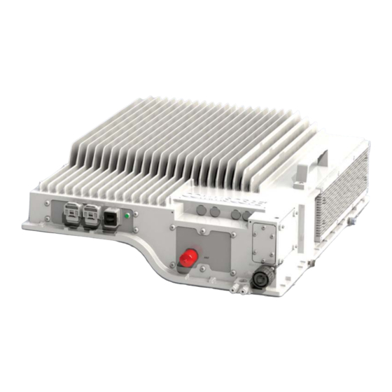
Page 9: Cap M Overview
All APs can only connect to a TEN or a Classic CAN. APs cannot connect to a Switching CAN or to a WIN. The CAP M is passively cooled and operates within the following temperature ranges: • -33°C to +52°C (-27.4°F to 125.6°F) is rated for indoor and outdoor (IP66) installations; see "Determine the Mounting Site” on page 16 • has a typical power consumption of 140W; see also "Determine the Power Consumption of the CAP M” on • page 16. ™ M0201AJB Medium Power Carrier Access Point Installation Guide © October 2018 CommScope, Inc. Page 5... -
Page 10: Connectors And Led For The Cap M
Connects to any of the following (graphic shows the port populated): connector • Vac—Main power (Vac or Vdc) • Vdc—Remote DC power supply or a Hybrid Fiber Junction Box. ™ Medium Power Carrier Access Point Installation Guide M0201AJB Page 6 © October 2018 CommScope, Inc. -
Page 11: Notch-Filter Connectors
Figure 3. Notch-Filter Connector on the CAP M 7E/80-85/17E/19 CAP M Hardware Options The following sections describe hardware options for the CAP M. Single Mounting Bracket The Single Mounting Bracket (CommScope PN 7821954-xx) provides the mounting brackets required to mount an CAP M to a wall or other vertical, flat surface. See "Mount a CAP M Using a Single Mounting Bracket” on page 25. ™ M0201AJB Medium Power Carrier Access Point Installation Guide © October 2018 CommScope, Inc. Page 7... -
Page 12: Dual Mounting Bracket
This is the RJ-45 connector that you use to attach an auxiliary Ethernet device. The Ethernet OCTIS Kit must be ordered separately. 1 OCTIS is a trademark of RADIALL. ™ Medium Power Carrier Access Point Installation Guide M0201AJB Page 8 © October 2018 CommScope, Inc. -
Page 13: Safely Working With Era Hardware
Due to power dissipation, the CAP M may reach a very high temperature. Do not operate this equipment on or close to flammable materials. Use caution when servicing the CAP M. ™ M0201AJB Medium Power Carrier Access Point Installation Guide © October 2018 CommScope, Inc. Page 9... -
Page 14: General Installation Safety Requirements
Do not remove caps from any of the connectors until instructed to do so. The CAP M is to be used only with CommScope (NEC Class 2) or Limited Power Source Era Subrack, or equivalent. Read and observe all the warning labels attached to the unit. Make sure that all warning labels are kept in a legible condition. -
Page 15: Compliance
• 1 for frequencies from 2 GHz to 300 GHz • Notice: Installation of this equipment is in full responsibility of the installer, who has also the responsibility, that cables and couplers are calculated into the maximum gain of the antennas, so that this value, which is filed in the FCC Grant and can be requested from the FCC data base, is not exceeded. The industrial boosters are shipped only as a naked booster without any installation devices or antennas as it needs for professional installation. Notice: For installations which have to comply with FCC/ISED requirements: English: This device complies with FCC Part 15. Operation is subject to the following two conditions: (1) this device may not cause interference, and (2) this device must accept any interference, including interference that may cause undesired operation of the device. This device complies with Health Canada's Safety Code. The installer of this device should ensure that RF radiation is not emitted in excess of the Health Canada's requirement. Information can be obtained at http://www.hc-sc.gc.ca/ewh-semt/pubs/radiation/radio_guide-lignes_direct-eng.php. Changes or modifications not expressly approved by the party responsible for compliance could void the user's authority to operate the equipment. Antenna Stmt for ISED: This device has been designated to operate with the antennas having a maximum gain of 9 dBi. Antennas having a gain greater than 9 dBi are prohibited for use with this device without consent by ISED regulators. The required antenna impedance is 50 ohms. The antenna(s) used for this transmitter must be installed to provide a separation distance of at least 100 cm from all persons and must not be co-located or operating in conjunction with any other antenna or ™ M0201AJB Medium Power Carrier Access Point Installation Guide © October 2018 CommScope, Inc. Page 11... - Page 16 For Canada and US, components used to reduce the Overvoltage Category shall comply with the requirements of IEC 61643-series. As an alternative, components used to reduce the Overvoltage Category may comply with ANSI/IEEE C62.11, CSA Certification Notice No. 516, CSA C22.2 No. 1, or UL 1449. Suitability of the component for the application shall be determined for the intended installation. Notice: Corresponding local particularities and regulations must be observed. For national deviations, please refer to the respective documents included in the manual CD that is delivered with the unit. Note: For a Class B digital device or peripheral: This equipment has been tested and found to comply with the limits for a Class B digital device, pursuant to part 15 of the FCC Rules. These limits are designed to provide reasonable protection against harmful interference in a residential installation. This equipment generates, uses and can radiate radio frequency energy and, if not installed and used in accordance with the instructions, may cause harmful interference to radio communications. However, there is no guarantee that interference will not occur in a particular installation. If this equipment does cause harmful interference to radio or television reception, which can be determined by turning the equipment off and on, the user is encouraged to try to correct the interference by one or more of the following measures: Reorient or relocate the receiving antenna. • Increase the separation between the equipment and receiver. • Connect the equipment into an outlet on a circuit different from that to which the receiver is • connected. Consult the dealer or an experienced RF technician for help. • ™ Medium Power Carrier Access Point Installation Guide M0201AJB Page 12 © October 2018 CommScope, Inc.
-
Page 17: Equipment Symbols Used / Compliance
Indicates conformity with the RED directive 2014/53/EU and/or RoHS directive 2011/65/EU. Indicates conformity with the RED directive 2014/53/EU and RoHS directive 2011/65/EU certified by the notified body no. 0700. ™ M0201AJB Medium Power Carrier Access Point Installation Guide © October 2018 CommScope, Inc. Page 13... -
Page 18: Installing Cap Ms
SMF or MMF connects the CAP M via its Optical Port 1 to the OPT Card. • When cascading a Secondary CAP M or an external Ethernet device such as WiFi or an IP camera, you • must observe the following rules. To cascade two CAP Ms, use a fiber-optic cable. – SMF or MMF connects the Secondary CAP M via its Optical Port 1 to the Primary CAP M via its Optical – Port 2. You can connect the following to the Primary CAP M – a Secondary CAP M an Ethernet device both a Secondary CAP M and an Ethernet device. To add a Secondary AP, you must add an Optical OCTIS kit to the Primary CAP L, see "OCTIS Kits” on • page 8. To add an Ethernet device, you must add an RJ45 OCTIS kit to the Primary CAP L, see "OCTIS Kits” on • page 8. ™ Medium Power Carrier Access Point Installation Guide M0201AJB Page 14 © October 2018 CommScope, Inc. -
Page 19: Cat6A Cable Requirements For Ethernet Devices
SW10 wrench • Single Mount • Single Mounting Bracket (CommScope PN 7821954-xx) – Four M6 screw anchors rated for the mounting surface – Dual Mount • Dual Mounting Bracket (CommScope PN 7821955-xx) – Four M6 screw anchors rated for the mounting surface – For installations using the optional Hybrid Fiber Splice Box • Hybrid Fiber Splice Box (CommScope PN 7693816-xx) – Torx T20H screwdriver – Earth-bonding cable to ground the CAP M chassis • Fiber cleaning equipment. • ™ M0201AJB Medium Power Carrier Access Point Installation Guide © October 2018 CommScope, Inc. Page 15... -
Page 20: Determine The Power Consumption Of The Cap M
Dual Mounting Bracket (PN 7821955-xx) 19.2 42.3 40 88.2 A Hybrid Fiber Splice Box (PN 7693816-xx) adds 0.3 kg (.66 lbs.) to the total weights. Use the dimensions shown in Figure 4 on page 17 for Single Mount and Figure 5 on page 18 for Dual • Mount. ™ Medium Power Carrier Access Point Installation Guide M0201AJB Page 16 © October 2018 CommScope, Inc. - Page 21 Installing CAP Ms 502 mm (19.74”) 175 mm (6.88”) 566 mm (22.27”) Figure 4. Mounting Dimensions with the Single Mounting Bracket ™ M0201AJB Medium Power Carrier Access Point Installation Guide © October 2018 CommScope, Inc. Page 17...
- Page 22 Installing CAP Ms 502 mm (19.74”) 302 mm (11.88”) 565 mm (22.26”) Figure 5. Mounting Dimensions with the Dual Mounting Bracket ™ Medium Power Carrier Access Point Installation Guide M0201AJB Page 18 © October 2018 CommScope, Inc.
-
Page 23: Unpack And Inspect The Cap M And Optional Accessories
Fiber Splice Box to provide fiber and power to the CAP M. If the optional Hybrid Fiber Splice Box is not required for this installation, skip to "Mount the CAP M” on page Obtain the Hybrid Fiber Splice Box Kit (CommScope PN 7693816-xx). Follow the steps in "Unpack and Inspect the CAP M and Optional Accessories” on page 19. Open the Hybrid Fiber Splice Box and remove the installation kit that is inside. Using the parts from the Hybrid Fiber Splice Box, insert the Splice Holder and fasten it using a PTK 30x6 screw and one M4 washer. ™ M0201AJB Medium Power Carrier Access Point Installation Guide © October 2018 CommScope, Inc. Page 19... - Page 24 Installing CAP Ms From the Hybrid Fiber Splice Box Kit, insert Fiber Patch Cord in one of the cable glands indicated in the graphic to the right. Strip the insulation of the composite cable for 100 cm and the fibers for 90 cm, and then shorten the copper cables to 25 cm. Insert the composite cable in the first cable gland and separate the multi-fibers cable from the copper wires. It is necessary to remove the nut to perform this action. The cable must be fed through the nut and it must be retightened once finished. Bend the spliced fibers using the corner guides and fix the splices to the splice holder. Bend the optical cables as shown in the graphic to the right. ™ Medium Power Carrier Access Point Installation Guide M0201AJB Page 20 © October 2018 CommScope, Inc.
- Page 25 Installing CAP Ms 10 If a second splice holder is needed, it can be assembled using the M4 insulating washer and two M4 plain washers, as shown to the right. The required screw is a PTK30 x 12. 11 Remove the sealing nut and rubber of the cable gland and insert the optical cables. 12 Place each cable into one of the grooves of the seal insert. 13 Press the seal insert into the clamp ring opening. 14 Fix the optical cables inside the box using one cable tie and tight the sealing nut. 15 It is possible to separate the optical cables and use two different cable glands. Remove the sealing nut and rubber on each cable gland. 16 Close all unused grooves with the plastic cylinders, no matter if one or two cable glands are used. ™ M0201AJB Medium Power Carrier Access Point Installation Guide © October 2018 CommScope, Inc. Page 21...
- Page 26 Installing CAP Ms 17 Insert the copper wires in the first multiple terminal connectors. See markings on the internal support. Then fasten the copper cables inside the box using one cable tie. 18 Remove the sealing nut and insert the CAP M supply cable and tighten the sealing nut. 19 Connect the supply cable to the terminal strip and fix it inside the box using one cable tie. In the instance when two CAP Ms are in a dual mount or a cascade, it is possible to connect a second power supply cable. In the figure to the right, 1 and 2 refers to two CAP Ms. ™ Medium Power Carrier Access Point Installation Guide M0201AJB Page 22 © October 2018 CommScope, Inc.
-
Page 27: Mount The Cap M
Ensure that the static and dynamic strengths are adequate for the environmental conditions of the site. The mounting itself must not vibrate, swing or move in any way that might cause damage to the CAP M. ™ M0201AJB Medium Power Carrier Access Point Installation Guide © October 2018 CommScope, Inc. Page 23... -
Page 28: Mounting Orientation
ANT port pointing down, as shown in Figure ANT port poin ng down Figure 6. Mounting Orientation for a CAP M ™ Medium Power Carrier Access Point Installation Guide M0201AJB Page 24 © October 2018 CommScope, Inc. -
Page 29: Mount The Cap M To A Wall Or Vertical Surface
If this installation requires the optional Hybrid Fiber Splice Box to provide fiber and power to the CAP M, follow the steps in Mount a CAP M Using a Single Mounting Bracket Obtain the CAP M Single Mounting Bracket (CommScope PN 7821955-xx). Follow the steps in "Unpack and Inspect the CAP M and Optional Accessories” on page 19. Table 7 lists the parts that ship with the CAP M Single Mounting Bracket. Table 7. Parts List for CommScope PN 7821955-XX Description Quantity Single Wall-Mounting Bracket Refer to "Determine the Mounting Site” on page 16 to determine the mounting location, which must be able to support the weight and dimensions of the CAP M. - Page 30 (wall structure and materials). Use screw anchors that are rated for the mounting surface. Confirm that the Mounting Bracket is securely fastened to the wall. through are the four screw anchors ™ Medium Power Carrier Access Point Installation Guide M0201AJB Page 26 © October 2018 CommScope, Inc.
- Page 31 Installing CAP Ms From both sides of the CAP M: Loosen the M6 pins, leaving its washer in place. Remove the two M6 screws and their M6 plain and M6 split-lock washers; reserve the screws and washers as you will later reinstall them. Loosen the M6 pin Remove the M6x12 screw and its washers M6 plain washer M6 split-lock washer M6x12 screw ™ M0201AJB Medium Power Carrier Access Point Installation Guide © October 2018 CommScope, Inc. Page 27...
- Page 32 Installing CAP Ms Use both handles on the CAP M to lift it above the Mounting Bracket, and then lower it into place. The M6 pins that you loosened in Step 7 on page 27 must align with the Mounting Bracket slots, as shown below. ™ Medium Power Carrier Access Point Installation Guide M0201AJB Page 28 © October 2018 CommScope, Inc.
- Page 33 Installing CAP Ms On the right side of the CAP M, slide a washer over the threaded M6 pin, and then secure the CAP M to the Mounting Bracket by torquing the M6 pin to 11 N-m. Align the M6 pins with the Moun ng Bracket slots 10 Repeat Step 9 on the left side of the CAP M. ™ M0201AJB Medium Power Carrier Access Point Installation Guide © October 2018 CommScope, Inc. Page 29...
- Page 34 Installing CAP Ms On lower right of the CAP M, reinstall the M6x12 screw and its washers that you removed in Step 7 on page 27. Slide first the M6 plain washer and then the M6 split-lock washer over the M6x12 screw. Insert the M6x12 screw through the screw hole shown below, and screw it back into the CAP M chassis; torque to 11 N-m. M6x12 screw washer set 12 Repeat Step 11 on the left side of the CAP M. 13 Do one of the following: If this installation requires a Hybrid Fiber Splice Box, go to "Attach a Hybrid Fiber Splice Box to the • CAP M” on page 42. If this installation does not a Hybrid Fiber Splice Box, go to "Grounding the CAP M” on page 46. • ™ Medium Power Carrier Access Point Installation Guide M0201AJB Page 30 © October 2018 CommScope, Inc.
-
Page 35: Mount Two Cap Ms Using A Dual Mounting Bracket
(front of CAP M-2 faces out, and is back-to-back with CAP M 1) Figure 7. Two CAP Ms Back-to-Back in a Dual Mounting Bracket Do the following to mount two CAP Ms in a Dual Mounting Bracket. Obtain the Dual Mounting Bracket (CommScope PN 7821954-xx). Follow the steps in "Unpack and Inspect the CAP M and Optional Accessories” on page 19. Table 8 lists the parts that ship with the CAP M Dual Mounting Bracket. Table 8. Parts List for CommScope PN 7821954-XX Description Quantity Dual Wall Mounting Bracket ™ M0201AJB Medium Power Carrier Access Point Installation Guide ©... - Page 36 (wall structure and materials). Use screw anchors that are rated for the mounting surface. Confirm that the bracket is securely fastened to the wall. Dual Moun ng Bracket through are the four screw anchors ™ Medium Power Carrier Access Point Installation Guide M0201AJB Page 32 © October 2018 CommScope, Inc.
- Page 37 Installing CAP Ms From both sides of CAP M-1: Loosen the M6 pins, leaving its washer in place. Remove the two M6 screws and their M6 plain and M6 split-lock washers; reserve the screws and washers as you will later reinstall them. Loosen the M6 pin Remove the M6x12 screw and its washers M6 plain washer M6 split-lock washer M6x12 screw ™ M0201AJB Medium Power Carrier Access Point Installation Guide © October 2018 CommScope, Inc. Page 33...
- Page 38 (front of the CAP M-1 chassis faces the moun ng surface) M6 Pin with its washer on the inside of the bracket, against the CAP-M1 chasssis On the right side of the CAP M-1, torque the M6 pin to 11 N-m. 10 Repeat Step 9 on the left side of the CAP M. ™ Medium Power Carrier Access Point Installation Guide M0201AJB Page 34 © October 2018 CommScope, Inc.
- Page 39 Installing CAP Ms On lower right of the CAP M-1, reinstall the M6x12 screw and its washers that you removed in Step 7 on page 33. Slide first the M6 split-lock washer and then the M6 plain washer over the M6x12 screw. Insert the M6x12 screw through the screw hole shown below, and screw it back into the CAP M-1 chassis; torque to 11 N-m. M6x12 screw and washer set in hole closest to the moun ng surface 12 Repeat Step 11 on the left side of the CAP M-1. ™ M0201AJB Medium Power Carrier Access Point Installation Guide © October 2018 CommScope, Inc. Page 35...
- Page 40 Installing CAP Ms 13 From both sides of CAP M-2: Loosen the M6 pins, leaving its washer in place. Remove the two M6 screws and their washers; reserve the screws and washers as you will later reinstall them. Loosen the M6 pin Remove the M6 screw and its washer ™ Medium Power Carrier Access Point Installation Guide M0201AJB Page 36 © October 2018 CommScope, Inc.
- Page 41 CAP M-1) M6 Pin with its washer on the inside of the bracket, against the CAP-M2 chasssis 15 On the right side of the CAP M-2, torque the M6 pin to 11 N-m. 16 Repeat Step 15 on the left side of the CAP M. ™ M0201AJB Medium Power Carrier Access Point Installation Guide © October 2018 CommScope, Inc. Page 37...
- Page 42 Insert the M6x12 screw through the screw hole shown below, and screw it back into the CAP M chassis; torque to 11 N-m. M6x12 screw and washer set in hole furthest from the moun ng surface 18 Repeat Step 11 on the left side of CAP M-2. 19 Do one of the following: If this installation requires a Hybrid Fiber Splice Box, go to "Attach a Hybrid Fiber Splice Box to the • CAP M” on page 42. If this installation does not a Hybrid Fiber Splice Box, go to "Grounding the CAP M” on page 46. • ™ Medium Power Carrier Access Point Installation Guide M0201AJB Page 38 © October 2018 CommScope, Inc.
-
Page 43: Mount The Cap M To A 4" To 18" Pole
Dual-Moun ng Pole-Moun ng Bracket Bracket Back View Side View Front View Figure 8. Installation Views of the CAP M Pole Mounting Kit for Up to 18" Poles (CommScope PN 7692096-XX) Do the following to assemble the CAP M Pole Mounting Kit for Up to 18" Poles, mount the kit to a pole, and then mount the CAP M on the mounting kit. This procedure requires two installers. Obtain the CAP M Pole Mounting Kit for Up to 18" Poles (CommScope PN 7692096-XX). Obtain either a Single Mounting Bracket Kit (CommScope PN 7821955-xx) or a Dual Mounting Bracket Kit (CommScope PN 7821954-xx), as required for this installation. - Page 44 Installing CAP Ms Follow the steps in "Unpack and Inspect the CAP M and Optional Accessories” on page 19. Table 9 lists the parts that ship with the CAP M Pole Mounting Kit for Up to 18" Poles. Table 9. Parts List for CommScope PN 7692096-XX Description Quantity Description Quantity Pole-Mounting Bracket M8 Threaded Bolt Bracket M8 Hexagon Nut M6 Hexagon Nut M8 Plain Washer M6 Plain Washer M8 Split-Lock Washer M6 Split-Lock Washer M8 Nut Refer to "Determine the Mounting Site” on page 16 to determine the mounting location, which must be...
- Page 45 Bracket in the pole at the position at which the CAP M is to be attached to the pole. The eight threaded bolts will protrude to the other Threaded bolts side of the pile. 12 The second installer should now attach one of the Brackets to the top four threaded bolts that protrude past the pole. Install the M8 nut and washers in the order shown. Slide one M8 plain washer (12A) to one end of each of the four threaded bolts. Slide an M8 split-lock washer (12B) next to the M8 plain washer. Use an M8 nut (12C) to screw the end of the threaded bolts (with the nut and washer) to the welded nuts on the inner side of the top Pole-Mounting Bracket. Torque the M8 Hexagon Nut to 27 N-m. 13 Repeat Step 12, but this time attach the second Bracket to the bottom four threaded bolts. To mount the CAP M to the pole-mounting kit, follow the steps in "Mount a CAP M Using a Single Mounting Bracket” on page 25 or "Mount Two CAP Ms Using a Dual Mounting Bracket” on page 31, as appropriate for this installation. ™ M0201AJB Medium Power Carrier Access Point Installation Guide © October 2018 CommScope, Inc. Page 41...
-
Page 46: Attach A Hybrid Fiber Splice Box To The Cap M
• "Attaching a Hybrid Fiber Splice Box for a Dual Mount Installation” on page 44. • Attaching a Hybrid Fiber Splice Box for a Single Mount Installation Hang the Splice Box onto the Single Mounting Bracket on the right-hand side of the CAP M, as shown below. Single Moun ng Bracket Hybrid Fiber Splice Box ™ Medium Power Carrier Access Point Installation Guide M0201AJB Page 42 © October 2018 CommScope, Inc. - Page 47 Installing CAP Ms Remove the six neck screws (shown below) from the front cover of the Splice Box. Open the Splice Box. Attach an M4 x 25 pan-head screw to the upper hole, and a second M4 x 25 pan-head to the hole on the lower, right-hand side of the Splice Box. Close the Splice Box. Replace the six neck screws that you removed from the front cover of the Splice Box in Step 2 on page 43. Go to "Grounding the CAP M” on page 46. ™ M0201AJB Medium Power Carrier Access Point Installation Guide © October 2018 CommScope, Inc. Page 43...
-
Page 48: Attaching A Hybrid Fiber Splice Box For A Dual Mount Installation
Installing CAP Ms Attaching a Hybrid Fiber Splice Box for a Dual Mount Installation Break the left-hand side hook of the Splice Box bracket. This is necessary for proper mounting. Hang the Splice Box onto the Dual Mounting Bracket on the left-hand side of the CAP M, as shown below. Dual Moun ng Bracket Hybrid Fiber Splice Box ™ Medium Power Carrier Access Point Installation Guide M0201AJB Page 44 © October 2018 CommScope, Inc. - Page 49 Installing CAP Ms Remove the six neck screws (shown below) from the front cover of the Splice Box. Open the Splice Box. Attach an M4 x 25 pan-head screw to the upper hole, and a second M4 x 25 pan-head to the hole on the lower, left-hand side (shown at right) of the Splice Box. Close the Splice Box. Replace the six neck screws that you removed from the front cover of the Splice Box in Step 3 on page 45. Go to "Grounding the CAP M” on page 46. ™ M0201AJB Medium Power Carrier Access Point Installation Guide © October 2018 CommScope, Inc. Page 45...
-
Page 50: Grounding The Cap M
Do not use the grounding bolts to connect an external device. Connect an earth-bonding cable to the grounding bolt connections on the outside of the CAP M chassis, as shown below. Grounding bolts Loosen the M6 hex nut(s), and then connect the Plain washers earth-bonding cable between the two washers as shown to the right. Locking ring Secure the earth-bonding cable by tightening the M6hex nut(s) that you loosened in the preceding step. Connect the other end of the earth-bonding cable to a suitable permanent ground per local electrical code practices. Follow the steps in "Connect the CAP M Cables” on page 47. Earth-Bounding cable ™ Medium Power Carrier Access Point Installation Guide M0201AJB Page 46 © October 2018 CommScope, Inc. -
Page 51: Connect The Cap M Cables
Classic CAN 7680813 SFP+, 10GBase-LR, Single Mode 10km One placed in the TEN and paired with another in the Classic CAN If connecting an external Ethernet device such as WiFi or IP camera, an Ethernet OCTIS Kit (PN 7760652) • and appropriate CAT cable for the device. ™ M0201AJB Medium Power Carrier Access Point Installation Guide © October 2018 CommScope, Inc. Page 47... -
Page 52: Connect The Cap M To An Rf Antenna
If installing a CAP M with a Hybrid Fiber Splice Box (PN 7693816-xx), the optical fiber will be hanging from the Splice Box. Connect a Secondary CAP M (Optional) If appropriate for this installation, connect the Optical Port 2 connector. Note the maximum range listed in Table 10 on page 47. Raise the lever on the EMI/IP67 cap on Optical Port 2 connector and remove the cap. Remove the caps from the connectors on the SMF or MMF. Follow the local cleaning technique to clean the optical port for each SFP+ Module. Clean the connectors on the SMF or MMF following the fiber supplier’s recommendations. Install the SFP+ and Optical OCTIS Kit on the end of the fiber that will connect to the CAP M and connect that end of the SMF or MMF to the CAP M Optical Port 2 connector. (Refer to the technical data sheet that ships with the OCTIS Kit for further information.) Use another OCTIS Kit and the other SFP+ Module to connect the other end of the SMF or MMF to Optical Port 1 on the cascaded CAP M. ™ Medium Power Carrier Access Point Installation Guide M0201AJB Page 48 © October 2018 CommScope, Inc. -
Page 53: Connect An External Ethernet Device (Optional)
Make sure to connect the correct voltage to the CAP M. For the CAP M to operate, the Mains power must be connected to the CAP M Mains connector. Either an AC or a DC power cable is delivered with each CAP M—the type of power cable delivered is dependent on the type of power supply in the CAP M. ™ M0201AJB Medium Power Carrier Access Point Installation Guide © October 2018 CommScope, Inc. Page 49... -
Page 54: Cap M Ac Power Cable
CAP M DC Power Cable The standard CAP M DC power cable is a 3.2 m (10.5 ft) 13 AWG cable with a 4-pin Amphenol C016 series plug on one end to connect to the CAP M Mains connector. The other end of the cable is unterminated with 2 end splices to connect to the -48 Vdc power source. The standard DC power cable is shown in Figure 10. Amphenol Protec ve 4-Pin female connector end splice Black CAP M Mains connector Figure 10. CAP M DC Power Cable ™ Medium Power Carrier Access Point Installation Guide M0201AJB Page 50 © October 2018 CommScope, Inc. -
Page 55: Connect The Cap M Power
CAP M to plug or unplug the cable into the Mains connector. Dependent on the type of power supply used by the unit, wire the power cable to the junction box or receptacle. Refer to the color code and pin numbers shown in: Figure 9 on page 50 for the AC power cable • Figure 10 on page 50 for the DC power cable. • With the cable's Mains plug disconnected from the CAP M, turn the circuit breaker on, unscrew the plug's protective cover, and carefully test the plug with a voltmeter to ensure that the voltage and polarity are correct. Once the testing has been completed, turn off the circuit breaker. Unscrew the protective cover from the Mains connector of the unit. ™ M0201AJB Medium Power Carrier Access Point Installation Guide © October 2018 CommScope, Inc. Page 51... -
Page 56: Connect A Hybrid Fiber Splice Box
• end to the CAP M Hybrid Fiber Splice Box LC Fiber Pigtail to the supplied OCTIS connector and splice the other end of the fiber pigtail inside the • locally-mounted CAP M Hybrid Fiber Splice Box. Power the CAP M The CAP M is powered on as soon as power is connected to it. Under normal operating conditions, the Power LED turns on briefly when the unit is first detected. It will then go out briefly, followed by an initialization period during which the Power LED flashes slowly while the CAP M is configured. The Power LED remains a steady blue (not flashing) once the unit reaches a fully operational state, which typically occurs within 45 seconds. CAP M Power LED behavior is as follows: Off—CAP M is not powered on. • Steady blue—CAP M is powered on and operational. • Slow flashing blue—CAP M is powered on and initializing. • Rapid flashing blue—CAP M Unit Identifier active via the Flash LED function in the Era GUI. • ™ Medium Power Carrier Access Point Installation Guide M0201AJB Page 52 © October 2018 CommScope, Inc. -
Page 57: Contacting Commscope
Scan the QR Code to the right. • If viewing this document online as a PDF, click on the following URL link: • http://www.commscope.com/wisupport Enter the preceding URL into your web browser, and then press ENTER on your keyboard. • Waste Electrical and Electronic Equipment Recycling Country specific information about collection and recycling arrangements per the Waste Electrical and Electronic Equipment (WEEE) Directive and implementing regulations is available on CommScope’s website. To access information on the CommScope recycling program, do any of the following: Scan the QR Code to the right. • If viewing this document online as a PDF, click on the following URL link: • http://www.commscope.com/About-Us/Corporate-Responsibility-and-Sustainability/Environment/Rec ycling/ Enter the preceding URL into your web browser, and then press ENTER on your keyboard. • ™ M0201AJB Medium Power Carrier Access Point Installation Guide © October 2018 CommScope, Inc. Page 53... -
Page 58: Hardware To Software Mapping Information
Learning Center Login page. If you have an account, enter your Username and Password, and then click Login. (Click on the Reset • Password link if you do not have your login information.) If you don't have an account, click on the Create New User Account link under the Login button, and • follow the prompts. Once you have logged in, you will see a list of available class dates. Click the date you prefer and select the Enroll or Register Now button to enroll. Follow the prompts through the payment process. Click either the Available Training or Calendar tab to view other training courses. For training related questions, please contact the CommScope DAS and Small Cell Institute at one of the following emails, as appropriate for your location: Americas: DASTrainingUS@CommScope.com DASTrainingEMEA@CommScope.com EMEA: ™ Medium Power Carrier Access Point Installation Guide M0201AJB Page 54 © October 2018 CommScope, Inc. -
Page 59: Accessing Era User Documentation
Contacting CommScope Accessing Era User Documentation Scan the QR Code to the right to go directly to the CommScope DCCS Customer Portal, where you can access the DCCS user documentation. Alternatively, you can go to the following web address to access the portal: www.mycommscope.com Access to the Customer Portal requires a user account and password. On the Sign In page, do one of the following: If you have an account, enter your Email address and Password, and then click Sign In. • If you don’t have an account, click New user registration, and follow the prompts. • Click DCCS to open the site. Select your site, and then click on a product link to open the product page. Click on the title of any document to open it. ™ M0201AJB Medium Power Carrier Access Point Installation Guide © October 2018 CommScope, Inc. Page 55...
Need help?
Do you have a question about the Era CAP M 9 and is the answer not in the manual?
Questions and answers