
Related Manuals for CommScope ION E Series


Summary of Contents for CommScope ION E Series
- Page 1 ® -E Series Low Power Carrier Access Point Installation Guide • M0201AAC • April 2018...
- Page 2 ISCLAIMER This document has been developed by CommScope, and is intended for the use of its customers and customer support personnel. The information in this document is subject to change without notice. While every effort has been made to eliminate errors, CommScope disclaims liability for any difficulties arising from the interpretation of the information contained herein. The information contained herein does not claim to cover all details or variations in equipment, nor to provide for every possible incident to be met in connection with installation, operation, or maintenance. This document describes the performance of the product under the defined operational conditions and does not cover the performance under adverse or disturbed conditions. Should further information be desired, or should particular problems arise which are not covered sufficiently for the purchaser's purposes, contact CommScope. CommScope reserves the right to change all hardware and software characteristics without notice. OPYRIGHT © 2018 CommScope, Inc. All Rights Reserved. This document is protected by copyright. No part of this document may be reproduced, stored in a retrieval system, or transmitted, in any form or by any means, electronic, mechanical photocopying, recording, or otherwise without the prior written permission of CommScope. For patents see www.cs-pat.com. RADEMARKS All trademarks identified by ® or ™ are registered trademarks or trademarks, respectively, of CommScope, Inc. Names of other products mentioned herein are used for identification purposes only and may be trademarks and/or registered trademarks of their respective companies. Andrew Wireless Systems GmbH, 19-December-2017...
-
Page 3: Table Of Contents
Document Revision History ....................................1 Document Cautions and Notes..................................2 Abbreviations Used in this Guide ..................................2 CommScope Part Numbers ....................................2 ION-E Series System Overview ................................... 3 CAP L Overview ......................................4 CAP L Connectors, Ports, and LEDs................................... 5 CAP L with an Optical Fiber Interface................................. - Page 4 Waste Electrical and Electronic Equipment Recycling............................ 51 Hardware to Software Mapping Information..............................52 DCCS Technical Training ....................................52 Accessing ION-E Series User Documentation ..............................53 ION®-E Series Low Power Carrier Access Point Installation Guide M0201AAC Page iv © April 2018 CommScope, Inc.
-
Page 5: Document Overview
"Hardware to Software Mapping Information” on page Document Revision History This is the third release of the ION ® -E Series Low Power Carrier Access Point Installation Guide, CommScope Document Number M0201AAC, dated January 2018, which adds • support for the CAP L 17E/19/23/25TDD – "Required Distances Between CAP Ls and Antennas” on page 16 – updates • the required clearance between a CAP L and an antenna in "General Installation Safety Requirements” – on page 12 “Antenna Stmt for ISED:” and “Antenne Stmt pour ISDE:” on page 14. – M0201AAC ION®-E Series Low Power Carrier Access Point Installation Guide © April 2018 CommScope, Inc. Page 1... -
Page 6: Document Cautions And Notes
Single-Mode Fiber Fahrenheit Transport Expansion Node Federal Communications Commission Universal Access Point Gigabyte Volts, direct current Gigahertz Watts CommScope Part Numbers The CommScope ION-E part numbers in this installation guide are in the format of nnnnnnn-xx, where the “-xx” suffix indicates the latest release. Contact your local CommScope sales representative for the current release part number. ION®-E Series Low Power Carrier Access Point Installation Guide M0201AAC Page 2 © April 2018 CommScope, Inc. -
Page 7: Ion-E Series System Overview
UAP-N25 and UAP-XN25—similar in function as the UAP and UAP-X, the UAP-N25 and UAP-XN25 – feature a 25 MHz filter on one path (instead of the 80 MHz filter on a UAP or UAP-X). This allows coexistence of specific bands, such as Australia 850 MHz and 900 MHz. Low Power Carrier Access Point (CAP L)—interfaces with the CAN/TEN via a Cat6A cable or an – optical link. This allows the CAP L to provide data over Copper, Single-Mode Fiber (SMF), or Multi-Mode Fiber (MMF). Power for CAP Ls with a Copper Interface can be provided over Cat6A or External AC/DC. Power for CAP Ls with a Fiber Interface is provided over External AC/DC or remotely through hybrid fiber. Access Point WiFi IP Camera Cat6A MM/SM Fiber Figure 1. Basic ION-E System M0201AAC ION®-E Series Low Power Carrier Access Point Installation Guide © April 2018 CommScope, Inc. Page 3... -
Page 8: Cap L Overview
Figure 2. CAP L in an ION-E System The CAP L operates within the following temperature ranges • CAP L without a Fan Kit (passively cooled) – Optical units: -33°C to +40°C (-27.4°F to 104°F) Cat6A units: 0°C to +40°C (32°F to 104°F) CAP L with a Fan Kit, the maximum operating temperature increases to 55°C (131°F); see also "Fan – Kit” on page 10 is outdoor rated (IP67), however, the Cat6A units are not designed for outdoor use; see "Determine the • CAP L Mounting Site” on page 19 has a typical power consumption of 98W; see also • "Fan Kit” on page 10 – "Determine the Power Consumption of the CAP L” on page 18. – ION®-E Series Low Power Carrier Access Point Installation Guide M0201AAC Page 4 © April 2018 CommScope, Inc. -
Page 9: Cap L Connectors, Ports, And Leds
CAP L Overview CAP L Connectors, Ports, and LEDs The following sections identify the connectors, ports, and LEDs available on the different CAP L models. "CAP L with an Optical Fiber Interface” on page 6 • "CAP L with a Copper Interface and External DC Power” on page 7 • "CAP L with a Copper Interface and Power Cat6A Cable” on page 8 • "Powering a CAP L” on page 48 • "Fan Interface Port” on page 9. • M0201AAC ION®-E Series Low Power Carrier Access Point Installation Guide © April 2018 CommScope, Inc. Page 5... -
Page 10: Cap L With An Optical Fiber Interface
For information on the Auxiliary port in cascades, see "Cascade Rules” on page 17. Port A ships with factory-installed EMI/weatherproof plug, and must remain plugged if not in use. ION®-E Series Low Power Carrier Access Point Installation Guide M0201AAC Page 6 © April 2018 CommScope, Inc. -
Page 11: Cap L With A Copper Interface And External Dc Power
100 meters (328 feet). Port A ships with factory-installed EMI/weatherproof plug, and must remain plugged if not in use. For information on how to use the Auxiliary port in cascades, see "Cascade Rules” on page M0201AAC ION®-E Series Low Power Carrier Access Point Installation Guide © April 2018 CommScope, Inc. Page 7... -
Page 12: Cap L With A Copper Interface And Power Cat6A Cable
Maximum attached cable length is 100 meters (328 feet). Port A ships with factory-installed EMI/weatherproof plug, and must remain plugged if not in use. ION®-E Series Low Power Carrier Access Point Installation Guide M0201AAC Page 8 © April 2018 CommScope, Inc. -
Page 13: Fan Interface Port
Interface port The preceding graphic shows the proprietary 8-pin Fan Interface port, which is only available on CAP L units that ship with the factory-installed Fan Kit. If the CAP L being installed includes the Fan Kit option, the Fan Interface port will be cabled to the Fan Kit at the factory. If the CAP L being installed does not include the Fan Kit option, the Fan Interface port will be plugged. CAP L Accessory Options The following sections describe hardware options for the CAP L: "Fan Kit” on page 10 • "Flat Mounting Bracket Kit” on page 10 • "CAP L Mounting Bracket Kit” on page 10 • "CAP L Hybrid Fiber Splice Box Kit” on page 11 • "AC/DC Power Supply Kit” on page 11 • "OCTIS Kits” on page 11. • M0201AAC ION®-E Series Low Power Carrier Access Point Installation Guide © April 2018 CommScope, Inc. Page 9... -
Page 14: Fan Kit
• increases the maximum operating temperature to 55°C (131°F) • adds 3W power consumption to the CAP L; see "Determine the Power Consumption of the CAP L” on • page 18. is factory installed, but can be replaced in the field. • Flat Mounting Bracket Kit The Flat Mounting Bracket Kit (CommScope PN 7774353-xx) provides the mounting brackets required to mount an CAP L to a wall or other flat surface. See "Wall Mount a CAP L Using a Flat Mounting Bracket Kit” on page 26. CAP L Mounting Bracket Kit The CAP L Mounting Bracket Kit (CommScope PN 7774354-xx) provides the mounting brackets required to mount an CAP L to a wall or other flat surface when using the “CAP L Hybrid Fiber Splice Box Kit” or the “AC/DC Power Supply Kit.” ION®-E Series Low Power Carrier Access Point Installation Guide M0201AAC Page 10 © April 2018 CommScope, Inc. -
Page 15: Cap L Hybrid Fiber Splice Box Kit
Use with CAP Ls that have a Fiber or Copper Interface to cascade a Secondary copper unit, or to attach an auxiliary Ethernet device. 1 OCTIS is a trademark of RADIALL. M0201AAC ION®-E Series Low Power Carrier Access Point Installation Guide © April 2018 CommScope, Inc. Page 11... -
Page 16: Safely Working With Ion-E Hardware
Do not remove caps from any of the connectors until instructed to do so. The CAP L is to be used only with CommScope (NEC Class 2) or Limited Power Source ION-E Subrack, or equivalent. ION®-E Series Low Power Carrier Access Point Installation Guide... -
Page 17: Guard Against Damage From Electro-Static Discharge
RF exposure compliance may need to be addressed at the time of licensing, as required by the responsible FCC Bureau(s), including antenna co-location requirements of 1.1307(b)(3). Notice: For installations which have to comply with European EN50385 exposure compliance requirements, the following Power Density limits/guidelines (mW/cm²) according to ICNIRP are valid: 0.2 for frequencies from 10 MHz to 400 MHz • F (MHz) / 2000 for frequencies from 400 MHz to 2 GHz • 1 for frequencies from 2 GHz to 300 GHz • Notice: Installation of this equipment is in full responsibility of the installer, who has also the responsibility, that cables and couplers are calculated into the maximum gain of the antennas, so that this value, which is filed in the FCC Grant and can be requested from the FCC data base, is not exceeded. The industrial boosters are shipped only as a naked booster without any installation devices or antennas as it needs for professional installation. Notice: For installations which have to comply with FCC/ISED requirements: English: This device complies with FCC Part 15. Operation is subject to the following two conditions: (1) this device may not cause interference, and (2) this device must accept any interference, including interference that may cause undesired operation of the device. This device complies with Health Canada's Safety Code. The installer of this device should ensure that RF radiation is not emitted in excess of the Health Canada's requirement. Information can be obtained at http://www.hc-sc.gc.ca/ewh-semt/pubs/radiation/radio_guide-lignes_direct-eng.php. M0201AAC ION®-E Series Low Power Carrier Access Point Installation Guide © April 2018 CommScope, Inc. Page 13... - Page 18 aux expositions RF. Notice: The unit complies with Overvoltage Category II. It also complies with the surge requirement according to EN 61000-4-5 (fine protection); however, installation of an additional medium (via local supply connection) and/or coarse protection (external surge protection) is recommended depending on the individual application in order to avoid damage caused by overcurrent. For Canada and US, components used to reduce the Overvoltage Category shall comply with the requirements of IEC 61643-series. As an alternative, components used to reduce the Overvoltage Category may comply with ANSI/IEEE C62.11, CSA Certification Notice No. 516, CSA C22.2 No. 1, or UL 1449. Suitability of the component for the application shall be determined for the intended installation. Notice: Corresponding local particularities and regulations must be observed. For national deviations, please refer to the respective documents included in the manual CD that is delivered with the unit. Note: For a Class B digital device or peripheral: This equipment has been tested and found to comply with the limits for a Class B digital device, pursuant to part 15 of the FCC Rules. These limits are designed to provide reasonable protection against harmful interference in a residential installation. This equipment generates, uses and can radiate radio frequency energy and, if not installed and used in accordance with the instructions, may cause harmful interference to radio communications. However, there is no guarantee that interference will not occur in a particular installation. If this equipment does cause harmful interference to radio or television reception, which can ION®-E Series Low Power Carrier Access Point Installation Guide M0201AAC Page 14 © April 2018 CommScope, Inc.
-
Page 19: Equipment Symbols Used / Compliance
Indicates conformity with the RED directive 2014/53/EU and/or RoHS directive 2011/65/EU. Indicates conformity with the RED directive 2014/53/EU and RoHS directive 2011/65/EU certified by the notified body no. 0700. M0201AAC ION®-E Series Low Power Carrier Access Point Installation Guide © April 2018 CommScope, Inc. Page 15... -
Page 20: Installing Cap Ls
C A P L 17E/ 19/ 23/ 25TDD .178 7.02 .251 9.88 CAP L Installation Rules When installing a CAP L, you must observe the following rules. CAP L with a Copper Interface • Connects via its RJ-45 port to a CAT Card in the CAN/TEN – Each CAT Port can support two Copper CAP Ls, but you cannot exceed six CAP Ls per CAT Card, for – maximum totals of 24 CAP Ls in a straight cascade configuration, and 32 CAP Ls per WCS Subrack in a daisy-chain configuration, but you must adhere to the Copper CAP L powering rules. There can be a total of 12 CAP Ls connected to a CAT Card in a cascade configuration. The CAP L – connected to the CAT Card is the Primary CAP L, to which you can connect one self-powered Secondary CAP L. See "Cascade Rules” on page 17. ION®-E Series Low Power Carrier Access Point Installation Guide M0201AAC Page 16 © April 2018 CommScope, Inc. -
Page 21: Cascade Rules
You can connect up to 4 CAP Ls per OPT Card for a total of 16. – In a cascade, the CAP L connected to the OPT Card is the Primary CAP L, to which you can connect one – Secondary CAP L. Use of the Auxiliary ports in a cascaded system is limited as described below. • For CAP Ls with a Fiber Interface, only use the Auxiliary port on the Primary CAP L. – For CAP Ls with a Copper Interface, use the Auxiliary port on the Primary CAP L to connect one of the – following: a locally powered Secondary CAP L an external Ethernet device such as WiFi or an IP camera. The total 320 MHz RF bandwidth is shared between the two cascaded units, but can be shared unevenly; • that is, with more bandwidth going to either the Primary or Secondary CAP L—either CAP L can transmit all the 320 MHz RF bandwidth or any subset of it. After the Primary CAP L powers up, the Secondary CAP L will be discovered and power up on its own; for • information on how a CAP L powers up, see "Powering a CAP L” on page 48. M0201AAC ION®-E Series Low Power Carrier Access Point Installation Guide © April 2018 CommScope, Inc. Page 17... -
Page 22: Recommended Tools And Material
SFP+ Module consumption. Typical installation (sufficient for SM up to 10km or MM) would be 0.8W typical, 1.0W max for each SFP+ Module. ION®-E Series Low Power Carrier Access Point Installation Guide M0201AAC Page 18 © April 2018 CommScope, Inc. -
Page 23: Determine The Cap L Mounting Site
10.7 23.6 11.2 24.7 13.2 13.7 30.2 CAP L Hybrid Fiber Splice Box Kit 10.7 23.6 11.2 24.7 12.2 26.9 12.7 Use the dimensions shown in Figure 3 on page 20 through Figure 5 on page 21. • M0201AAC ION®-E Series Low Power Carrier Access Point Installation Guide © April 2018 CommScope, Inc. Page 19... - Page 24 [16.71"] 24mm [0.94"] 30mm [1.18"] Figure 4. Mounting Dimensions for a CAP L Mounted with the CAP L Hybrid Fiber Splice Box Kit ION®-E Series Low Power Carrier Access Point Installation Guide M0201AAC Page 20 © April 2018 CommScope, Inc.
-
Page 25: General Mounting Cautions
To maintain proper ventilation, keep at least 76 mm (3-inch) clearance around the CAP L. The installation site must be able to bear the weight of the CAP L; see Table 6 on page M0201AAC ION®-E Series Low Power Carrier Access Point Installation Guide © April 2018 CommScope, Inc. Page 21... -
Page 26: Unpack And Inspect The Cap L And Optional Accessories
• Only Optical Fiber CAP Ls with the optional Fan Kit can be installed outdoors. – Do not install Copper CAP Ls (that is, have Cat6A cabling) outdoors as they are not designed for – outdoor temperatures, nor do they have required lightning protection. Mounting instructions are divided into the sections listed below. The following sections apply to all installations. • "General Mounting Cautions” on page 21 – "Mounting Orientation for Wall Mounts” on page 24. – Follow the mounting instructions that are appropriate for this installation: • "Flat-Surface Mount a CAP L” on page 23 – "Wall Mount a CAP L Using a Flat Mounting Bracket Kit” on page 26 – "Ceiling Mount a CAP L with a Fan Kit” on page 35 – "Wall Mount a CAP L Using a AC/DC Power Supply Kit” on page 32. – ION®-E Series Low Power Carrier Access Point Installation Guide M0201AAC Page 22 © April 2018 CommScope, Inc. -
Page 27: Flat-Surface Mount A Cap L
If the CAP L does not have a Fan Kit, do not Flat-Suface Mount with the CAP L Fins facing down. Fins Facing down Figure 6. CAP L Orientation in Flat-Surface Mounting After you mount the CAP L on a flat surface, follow the steps in "Connect the CAP L Cables” on page 37. M0201AAC ION®-E Series Low Power Carrier Access Point Installation Guide © April 2018 CommScope, Inc. Page 23... -
Page 28: Wall Mount A Cap L
33°C (91°F). ANT connectors poin ng down Figure 7. Mounting Orientation for a CAP L without the Optional Fan Kit (Flat Mounting Bracket Shown) ION®-E Series Low Power Carrier Access Point Installation Guide M0201AAC Page 24 © April 2018 CommScope, Inc. - Page 29 "Flat-Surface Mount a CAP L” on page Ceiling-mount requirements are described in "Ceiling Mount a CAP L with a Fan Kit” on page M0201AAC ION®-E Series Low Power Carrier Access Point Installation Guide © April 2018 CommScope, Inc. Page 25...
-
Page 30: Wall Mount A Cap L Using A Flat Mounting Bracket Kit
Three M6-1.0 x 14mm screws a Fan Kit horizontally. Figure 9. CAP L (No Fan Kit) with Flat Mounting Bracket Kit (PN 7774353-xx) ION®-E Series Low Power Carrier Access Point Installation Guide M0201AAC Page 26 © April 2018 CommScope, Inc. - Page 31 NOTE: Install a CAP L that does not have a Fan Kit ver cally. Figure 10. CAP L with a Fan Kit and Flat Mounting Bracket Kit (PN 7774353-xx) Use four 5/16-inch or M8 lag screws (or whatever screw type is appropriate for the material to which the CAP L is to mounted on) to mount the CAP L to the wall. Follow the steps in "(Optional) Ground the CAP L” on page 36 if grounding is required or preferred. Follow the steps in "Connect the CAP L Cables” on page 37. M0201AAC ION®-E Series Low Power Carrier Access Point Installation Guide © April 2018 CommScope, Inc. Page 27...
-
Page 32: Wall Mount A Cap L Using A Cap L Hybrid Fiber Splice Box Kit
Wall Mount a CAP L Using a CAP L Hybrid Fiber Splice Box Kit Follow the steps in "Unpack and Inspect the CAP L and Optional Accessories” on page 22. Refer to "Determine the CAP L Mounting Site” on page 19 to determine the mounting location, which must be able to support the weight and dimensions of the CAP L. Refer to "Mounting Orientation for Wall Mounts” on page 24 to determine the mounting orientation of the CAP L. Assemble the cables in the Hybrid Fiber Splice Box. Open the Hybrid Fiber Splice Box and remove the installation kit that is inside. Using the parts from the Hybrid Fiber Splice Box, insert the Splice Holder and fasten it using a PTK 30x6 screw and one M4 washer. From the CAP L Hybrid Fiber Splice Box Kit, insert Fiber Patch Cord in one of the cable glands indicated in the graphic to the right. Strip the insulation of the composite cable for 100 cm and the fibers for 90 cm, and then shorten the copper cables to 25 cm. ION®-E Series Low Power Carrier Access Point Installation Guide M0201AAC Page 28 © April 2018 CommScope, Inc. - Page 33 Installing CAP Ls Insert the composite cable in the first cable gland and separate the multi-fibers cable from the copper wires. It is necessary to remove the nut to perform this action. The cable must be fed through the nut and it must be retightened once finished. Bend the spliced fibers using the corner guides and fix the splices to the splice holder. Bend the optical cables as show in the picture to the right. If a second splice holder is needed, it can be assembled using the M4 insulating washer and two M4 plain washers, as shown to the right. The required screw is a PTK30 x 12. Mount the internal support Splice Box ION-U RU using three PTK30 x 6 screws. Remove the sealing nut and rubber of the cable gland and insert the optical cables. M0201AAC ION®-E Series Low Power Carrier Access Point Installation Guide © April 2018 CommScope, Inc. Page 29...
- Page 34 Installing CAP Ls Place each cable into one of the grooves of the seal insert. Press the seal insert into the clamp ring opening. m Fix the optical cables inside the box using one cable tie and tight the sealing nut. It is possible to separate the optical cables and use two different cable glands. Remove the sealing nut and rubber on each cable gland. Close all unused grooves with the plastic cylinders, no matter if one or two cable glands are used. Insert the copper wires in the first multiple terminal connectors. See markings on the internal support. Then fasten the copper cables inside the box using one cable tie. Remove the sealing nut and insert the Remote Unit supply cable and tighten the sealing nut. ION®-E Series Low Power Carrier Access Point Installation Guide M0201AAC Page 30 © April 2018 CommScope, Inc.
- Page 35 Installing CAP Ls Connect the supply cable to the terminal strip and fix it inside the box using one cable tie. It is possible to connect a second supply cable. In case of using remote unit Vdc/100 connect the supply cable as shown besides. Refer to markings on the internal support. Assemble and mount the CAP L Hybrid Fiber Splice Box Kit and the CAP L, as described below and as shown in Figure 11 on page 32, which shows a CAP L with Fan Kit (installation for a CAP L without a Fan Kit is the same). Attach the Hybrid Fiber Splice Box to the Wall Bracket with the three captive screws already installed in the Splice Box. Attach the assembled Hybrid Splice Box and Wall Mounting Bracket to the selected mounting location. Use the six M6-1.0 x14mm screws to attach the two Angled Mounting Brackets to the Wall Mounting Bracket. Put the top two flange-head screws halfway into the mounting brackets, and then use them to “hang” the CAP L in the Wall Mounting Bracket. Attach the bottom two flange-head screws. iii Tighten all four screws. From the CAP L Hybrid Fiber Splice Box Kit: Attach the Local Power Jumper to the CAP L power connector. Attach the Fiber Patch Cord to the CAP L Port 1; the other end was attached in Step 4c (page 28) to one of the cable glands. M0201AAC ION®-E Series Low Power Carrier Access Point Installation Guide © April 2018 CommScope, Inc. Page 31...
-
Page 36: Wall Mount A Cap L Using A Ac/Dc Power Supply Kit
Figure 11. CAP L with Fan Kit, CAP L Mounting Bracket Kit, and CAP L Hybrid Fiber Splice Box Kit Follow the steps in "(Optional) Ground the CAP L” on page 36 if grounding is required or preferred. Follow the steps in "Connect the CAP L Cables” on page 37. Wall Mount a CAP L Using a AC/DC Power Supply Kit Refer to and observe all cautions listed in "General Mounting Cautions” on page 21. Refer to "Determine the CAP L Mounting Site” on page 19 to determine the mounting location, which must be able to support the weight and dimensions of the CAP L. Refer to "Mounting Orientation for Wall Mounts” on page 24 to determine the mounting orientation of the CAP L. Follow the steps in "Unpack and Inspect the CAP L and Optional Accessories” on page 22. ION®-E Series Low Power Carrier Access Point Installation Guide M0201AAC Page 32 © April 2018 CommScope, Inc. - Page 37 Moun ng Bracket Figure 12. CAP L (No Fan Kit) with AC/DC Power Supply Kit (PN 7775087-xx) and CAP L Mounting Bracket Kit (7774354-xx) M0201AAC ION®-E Series Low Power Carrier Access Point Installation Guide © April 2018 CommScope, Inc. Page 33...
- Page 38 Figure 13. CAP L with Fan Kit and with AC/DC Power Supply Kit (PN 7775087-xx) and CAP L Mounting Bracket Kit (PN 7774354-xx) ION®-E Series Low Power Carrier Access Point Installation Guide M0201AAC Page 34 © April 2018 CommScope, Inc.
-
Page 39: Ceiling Mount A Cap L
Ceiling Mount a CAP L without a Fan Kit A CAP L that does not have a Fan Kit should only be installed above a suspended ceiling on a flat surface, using the steps in "Flat-Surface Mount a CAP L” on page 23. Ceiling Mount a CAP L with a Fan Kit Follow the steps in "Unpack and Inspect the CAP L and Optional Accessories” on page 22. Refer to and observe all cautions listed in "General Mounting Cautions” on page 21. Refer to "Determine the CAP L Mounting Site” on page 19 to determine the mounting location, which must be able to support the weight and dimensions of the CAP L. M0201AAC ION®-E Series Low Power Carrier Access Point Installation Guide © April 2018 CommScope, Inc. Page 35... -
Page 40: (Optional) Ground The Cap L
The CAP L is equipped with an M6 grounding stud located on the back of the unit; however, grounding is not necessary. CAP Ls are classified as low-voltage devices and do not have internal power supplies. CommScope recommends checking your local and national electrical codes to determine if grounding is a requirement. -
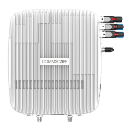
Page 41: Connect The Cap L Cables
Op cal Op cal Auxiliary Power Port 2 Port 1 port connector Figure 14. Connectors on a CAP L with an Optical Fiber Interface M0201AAC ION®-E Series Low Power Carrier Access Point Installation Guide © April 2018 CommScope, Inc. Page 37... - Page 42 17E and 19 AWS1700 / PCS1900 17E and 19 Remove the IP67/EMI blank plug from the ANT 1/2 connector. Connect the passive multi-band antenna to the ANT 1 or ANT 2 connector using coaxial cable with the least amount of loss possible. If the 50 coaxial cable has a push-pull connector, make sure the cable is seated firmly in the ANT Ω • 1 or ANT 2 connector. If the 50 coaxial cable has a threaded connector, torque the connector 5 N-m (3.69 ft-lb). Do not Ω • over-tighten the connector. Connect the other end of the 50 coaxial cable to the passive antenna installed in Step b on page 38. Ω ION®-E Series Low Power Carrier Access Point Installation Guide M0201AAC Page 38 © April 2018 CommScope, Inc.
- Page 43 IP cameras. Cable Port A as appropriate for this installation. Port A must be plugged if not in use. Raise the lever on the EMI/IP67 cap on Port A and remove the cap. Install the Ethernet OCTIS Kit on the end of the cable that will connect to the CAP L, and then connect that end of the cable to CAP L Port A. (Refer to the technical data sheet that ships with the OCTIS Kit for further information.) This cable cannot exceed 3 meters (9.8 feet). Connect the other end of the CAT cable to the Ethernet port of the auxiliary device. M0201AAC ION®-E Series Low Power Carrier Access Point Installation Guide © April 2018 CommScope, Inc. Page 39...
-
Page 44: Cable A Cap L With A Copper Interface
For information on how to test your Cat6A cables and connections, see "Cat6A Specifications and Testing Requirements” on page Plenum rated cable must be used wherever it is required by local electrical codes. • Shielded twisted pair is not required unless operating in a high RFI/EMI environment. • An ION-E system requires a minimum Signal-to-Noise Ratio (SNR) of 25 dB, and Alien Crosstalk (AXT) • must not degrade SNR on any cable by more than 0.5dB. Cat6A cable wire size requirements are as follows: • 23 AWG Cat6A cable (minimum EIA/TIA standards) must be used between RJ-45 connector points – 24 AWG is the minimum wire size allowed for a Cat6A Patch Cord. – CommScope strongly recommends using factory terminated and tested Cat6A Patch Cord. • ION®-E Series Low Power Carrier Access Point Installation Guide M0201AAC Page 40 © April 2018 CommScope, Inc. - Page 45 Note: References to Cat6A is inclusive of all Cat6A Cables, Cat6A Patch Cords, and Patch Panels Figure 16. Maximum Cat6A Cable Lengths from CAT Card to CAP L M0201AAC ION®-E Series Low Power Carrier Access Point Installation Guide © April 2018 CommScope, Inc. Page 41...
- Page 46 Note: References to Cat6A is inclusive of all Cat6A Cables, Cat6A Patch Cords, and Patch Panels. Figure 18. Maximum Cat6A Cable Length between a CAP L and an Ethernet Device ION®-E Series Low Power Carrier Access Point Installation Guide M0201AAC Page 42 © April 2018 CommScope, Inc.
-
Page 47: Cable A Cap L With A Copper Interface And External Dc Power
Ω a threaded connector. Following the rules in "Cat6A Cable Requirements for CAP Ls with a Copper Interface” on page 40, • obtain Cat6A cable that is of sufficient length to reach from the CAP L to the ION-E CAN/TEN. All installations require one Ethernet OCTIS Kit (PN 7760652 RJ-45). Additional Ethernet OCTIS Kits • are required (one each) for cascading a Secondary CAP L and/or connecting an external Ethernet device such as WiFi or an IP camera. If connecting to an external Ethernet device such as WiFi or an IP camera, obtain the appropriate CAT • cable for the protocol to which the CAP L will connect. This model supports a 1000 BASE-T and 802.3at Class 4 Power over Cat6A Ethernet connection. A single CAP L can support one auxiliary Ethernet device. – A cascaded CAP L pair can support one auxiliary device. – Follow the rules in "Cat6A Cable Requirements for CAP Ls with a Copper Interface” on page 40, all – Cat6A cable requirements and cable-length rules between a Primary and Secondary CAP L also apply to connecting an external Ethernet device. M0201AAC ION®-E Series Low Power Carrier Access Point Installation Guide © April 2018 CommScope, Inc. Page 43... - Page 48 Port 2 is plugged as it is not used in this configuration. (Optional) Port A (Auxiliary port) provides a cascade connection to an optional locally powered cascaded CAP L, or provides a connection to external Ethernet devices such as WiFi and IP cameras. Cable Port A as appropriate for this installation. Port A must be plugged if not in use. Raise the lever on the EMI/IP67 cap on Port A and remove the cap. Install the Ethernet OCTIS Kit on the end of the cable that will connect to the CAP L, and then connect that end of the cable to CAP L Port A. (Refer to the technical data sheet that ships with the OCTIS Kit for further information.) Connect the other end of the CAT cable to the Ethernet port of the auxiliary device. ION®-E Series Low Power Carrier Access Point Installation Guide M0201AAC Page 44 © April 2018 CommScope, Inc.
-
Page 49: Cable A Cap L With A Copper Interface And Power Over Cat6A Cable
Cable a CAP L with a Copper Interface and Power over Cat6A Cable Figure 20 identifies the connectors on a CAP L with Copper Interface; corresponding cables and connectors are shown. For details on the ports, see "CAP L with a Copper Interface and Power Cat6A Cable” on page 8. Port Cat6A Port 1 Power Auxiliary connector port Figure 20. Connectors on a CAP L with a Copper Interface M0201AAC ION®-E Series Low Power Carrier Access Point Installation Guide © April 2018 CommScope, Inc. Page 45... - Page 50 Ω If necessary, repeat Step 2 on page 46 to connect a 50 coaxial cable to the other ANT connector. Ω The Power connector and the Port 2 connector are plugged as they are not used in this configuration. ION®-E Series Low Power Carrier Access Point Installation Guide M0201AAC Page 46 © April 2018 CommScope, Inc.
- Page 51 Port A must be plugged if not in use. Raise the lever on the EMI/IP67 cap on Port A and remove the cap. Install an Ethernet OCTIS Kit ton the end of the cable that will connect to the CAP L, and then connect that end of the cable to CAP L Port A. (Refer to the technical data sheet that ships with the OCTIS Kit for further information.) Connect the other end of the cable to the Ethernet port of the auxiliary device. Connect the Vdc Power connector as appropriate for this installation. For a CAP L with no local power supply and no hybrid fiber cable, connect a power cable (not supplied • by CommScope) to the proprietary 4-pin, 36 to 60 Vdc Power connector on the CAP L. For a CAP L powered by the CAP L Hybrid Fiber Splice Box (PN 7774354-xx), connect the power cable • the proprietary 4-pin, 36 to 60 Vdc Power connector on the CAP L, and terminate the other end in the Hybrid Fiber Splice Box. Connect the LC Fiber Jumper to supplied OCTIS connector, and splice the other end of the fiber jumpers inside the locally-mounted Hybrid Fiber Splice Box. For a CAP L with the optional AC/DC Power Supply Kit (PN 7775087-xx), connect its Local Power • Jumper Cable Assembly to the proprietary 4-pin, 36 to 60 Vdc Power connector on the CAP L. The CAP L is powered on as soon as you connect the Local Power Jumper Cable Assembly to a power source; see "Powering a CAP L” on page 48. M0201AAC ION®-E Series Low Power Carrier Access Point Installation Guide © April 2018 CommScope, Inc. Page 47...
-
Page 52: Powering A Cap L
There is an installation problem, such as a defective cable or connector, a cable that is too long, or a cable crosstalk problem. Any of these problems can lead to inadequate SNR at the remote unit and an inability to link. (This is the most likely cause if this is a newly-installed unit.) This condition can also be triggered when a crystal oscillator has aged over the course of several years. In this case, the failure to link at startup will initiate a self-calibration process which can take several minutes. Once this self-calibration is complete, the unit will resume normal operation. (This is the most likely cause for units that have worked correctly in the past.) Using the Power-Down Button If you press the CAP L Power-Down button, the CAP L will go into sleep mode. This allows you to safely • disconnect any cables connected to the CAP L. If you press the Power-Down button, the only way to bring the CAP L back to a fully operational state, is • to do one of the following: Disconnect the data cable from Port 1, and then reconnect it. – For an externally-powered CAP L, remove the power cable for 10 seconds, and then reconnect it. – ION®-E Series Low Power Carrier Access Point Installation Guide M0201AAC Page 48 © April 2018 CommScope, Inc. -
Page 53: Cap L Maintenance
Bo om of CAP L with Flat Moun ng Bracket 240W AC/DC Power Supply Kit Enclosure Enclosure vents vents Figure 21. Examples of CAP L Fan Vent Locations M0201AAC ION®-E Series Low Power Carrier Access Point Installation Guide © April 2018 CommScope, Inc. Page 49... -
Page 54: Cat6A Specifications And Testing Requirements
Figure 22. ION-E End-to-End Channel Some cables list their performance in “typical” performance values. However, sweep-testing is necessary to confirm actual performance. CommScope strongly recommends using Cat6A cable that has been tested to the listed frequency with test confirmation available for inspection. -
Page 55: Contacting Commscope
• If viewing this document online as a PDF, click on the following URL link: • http://www.commscope.com/wisupport Enter the preceding URL into your web browser, and then press ENTER on your keyboard. • Waste Electrical and Electronic Equipment Recycling Country specific information about collection and recycling arrangements per the Waste Electrical and Electronic Equipment (WEEE) Directive and implementing regulations is available on CommScope’s website. To access information on the CommScope recycling program, do any of the following: Scan the QR Code to the right. • If viewing this document online as a PDF, click on the following URL link: • http://www.commscope.com/About-Us/Corporate-Responsibility-and-Sustainability/Environment/Rec ycling/ Enter the preceding URL into your web browser, and then press ENTER on your keyboard. • M0201AAC ION®-E Series Low Power Carrier Access Point Installation Guide © April 2018 CommScope, Inc. Page 51... -
Page 56: Hardware To Software Mapping Information
Learning Center Login page. If you have an account, enter your Username and Password, and then click Login. (Click on the Reset • Password link if you do not have your login information.) If you don't have an account, click on the Create New User Account link under the Login button, and • follow the prompts. Once you have logged in, you will see a list of available class dates. Click the date you prefer and select the Enroll or Register Now button to enroll. Follow the prompts through the payment process. Click either the Available Training or Calendar tab to view other training courses. For training related questions, please contact the CommScope DAS and Small Cell Institute at one of the following emails, as appropriate for your location: Americas: DASTrainingUS@CommScope.com DASTrainingEMEA@CommScope.com EMEA: ION®-E Series Low Power Carrier Access Point Installation Guide M0201AAC Page 52 © April 2018 CommScope, Inc. -
Page 57: Accessing Ion-E Series User Documentation
Contacting CommScope Accessing ION-E Series User Documentation Scan the QR Code to the right to go directly to the CommScope DCCS Customer Portal, where you can access the DCCS user documentation. Alternatively, you can go to the following web address to access the portal: https://www.mycommscope.com Access to the Customer Portal requires a user account and password. On the Sign In page, do one of the following: If you have an account, enter your Email address and Password, and then click Sign In. • If you don’t have an account, click New user registration, and follow the prompts. • Click DCCS to open the site. Select your site, and then click on a product link to open the product page. Click on the title of any document to open it. M0201AAC ION®-E Series Low Power Carrier Access Point Installation Guide © April 2018 CommScope, Inc. Page 53... - Page 58 Contacting CommScope ION®-E Series Low Power Carrier Access Point Installation Guide M0201AAC Page 54 © April 2018 CommScope, Inc.
Need help?
Do you have a question about the ION E Series and is the answer not in the manual?
Questions and answers