
Related Manuals for King Industrial KC-60FX


Summary of Contents for King Industrial KC-60FX
-
Page 1: Instruction Manual
6’’ WOODWORKING JOINTER MODEL: KC-60FX INSTRUCTION MANUAL COPYRIGHT 2000 BY KING CANADA TOOLS INC. -
Page 2: General Safety Rules
GENERAL SAFETY RULES W W A A R R N N I I N N G G : : Do not attempt to operate until you have read thouroughly and have understood all instructions, rules ect. contained in this manual. Failure to comply can result in accidents involving fire, electric shock, or personal injury. - Page 3 13. DO NOT OVERREACH. Keep proper footing and balance at all times. 14. MAINTAIN MACHINE IN TOP CONDITION. Keep machine clean for best and safest performance. Follow instructions for lubricating and changing accessories. 15. DISCONNECT THE MACHINE FROM POWER SOURCE. Before servicing and when changing accessories, or when mounting and remounting motor.
-
Page 4: Unpacking The Machine
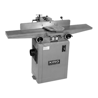
UNPACKING THE MACHINE 1. Cafefully unpack the machine. 2. Check to see if there is any damage which occured to the machine during transportation. Report to your local distributor if there is damage. 3. Check to see if there are any parts missing. If so, contact your local distributor. CLEANING THE MACHINE 1. - Page 5 LEGEND OF THE MACHINE 1. Outfeed Table Adjustment Handwheel. 2. Outfeed Table. 3. Fence. 4. Fence Movement Fix Lever. 5. Fence Angle Adjustment Lever. 6. Depth Scale. 7. Lever. 8. Cutterhead Guard. 9. Spring Knob. 10. Infeed Table. 11. Infeed Table Adjustment Handwheel. 12.
-
Page 6: Specifications
SPECIFICATIONS Cutting Capacity Width........6-1/8’’ (155mm) Cutting Capacity Depth........1/2’’ (12.7mm) Rabbeting Capacity..........1/2’’ (12.7mm) Cutterhead: Cutterhead Speed..........5,000 R.P.M. Cuts per Minute..............15,000 Number of Knives..............3 Diameter..............2.4’’ (61mm) Table: Dimensions.......7.3’’ (185mm) X 45’’ (1143mm) Height..............32.3’’ (820mm) Fence: Dimensions........4’’ (102mm) X 28’’ (710mm) Tilts Right................45 Positive Stops..............90 , 45 Overall Dimensions:... - Page 7 LOOSE PARTS BAG 1. Stand Mounting Screws with Washers........3 pcs. 2. Open End Wrench......8 X10 (1 pc.), 12 X14 (1 pc.) 3. Screwdriver................1 pc. 4. Belt Guard Lock Screw........1/4’’ X 3/4’’ (4 pcs.) 5. Allen Wrench............3mm (1 pc.) 6. Belt Guard................1 pc.
-
Page 8: Power Connections
POWER CONNECTIONS Set aside an electrical circuit that is used exclusively for tools. It should be at least a #12 wire and protected with a 15 AMP time lag fuse. Before connecting the motor to the power source, make sure that the voltage is the same as indicated on the machine, and that the machine is turned off. -
Page 9: Extension Cords
EXTENSION CORDS Check the condition of the extension cord regularly. Use a three wire extension cord with a three prong plug, and make sure it is plugged into an appropriate three hole receptacle. If you must use a two prong adapter temporarily, make sure the grounding extension on the adapter is connected to a permanent ground. -
Page 10: Starting And Stopping The Jointer
STARTING AND STOPPING THE JOINTER 1. The machine switch is located at the right side of the machine. 2. Press the ‘ON’ switch to start the machine. 3. Press the ‘OFF’ switch to stop the machine. DEPTH OF CUT ADJUSTMENT DEPTH ADJUSTMENT HANDWHEEL (A) 1. - Page 11 DEPTH OF CUT LIMIT 1. Never cut to a depth of more than 1/8 of an inch in a single feed. 2. The infeed table is fitted with a depth limit guard (A) to prevent cuts exceeding 1/8 of an inch. 3.
- Page 12 MOUNTING THE JOINTER ONTO THE STAND 1. The stand top has been predrilled with three holes for fastening the jointer onto the enclosed stand. 2. The infeed end of the jointer should be fastened to the front two holes (A) of the stand. 3.
- Page 13 MOUNTING THE FENCE ONTO THE TABLE 1. The fence (A) shall be mounted at the rear side of the table. 2. Before installing the fence, remove the lock nut from the fixing shaft (F). 3. Place the fence on the table and align the slot (C) with the gib (D), then insert the fixing shaft (F) through the opening (E).
- Page 14 SETTING FENCE AT A 90 ANGLE 1. Before adjusting the fence at a 90 angle, adjust the positionning of the infeed table. Adjust the infeed table so that it is parallel with the outfeed table. 2. Loosen the lock lever (A). Move the fence towards the front of the machine so that it leans on the table.
- Page 15 TILTING THE FENCE 1. The fence can be tilted backwards. 2. Unlock lock handle (A). Flip set plate (B) upwards and pull on fence lever (C) to tilt the fence backward. 3. To obtain a 45 angle, place a precision combination square on the table and against the fence.
-
Page 16: Replacing The Knives
REPLACING THE KNIVES 1. Before replacing the knives, be sure to disconnect the machine from the power source. 2. Remove the cutterhead guard. 3. Loosen the four fixing screws (A) that tighten the knives. 4. Remove the knife (C). 5. Remove the fixing gib (B). 6. -
Page 17: Knife Height Adjustment
KNIFE HEIGHT ADJUSTMENT 1. The knife height should be adjusted so that it is 1/16’’ over the cutterhead drum. 2. Use knife gauge (E) to adjust the knife height. The knife gauge must come in contact with the knife. To do so, use a hex. key to turn the screw (D) to make contact with the knife gauge. - Page 18 ADJUSTING THE KNIFE AND OUTFEED TABLE 1. Turn off and unplug the machine. 2. Adjust the height of the rear table until it is 1/16’’ above the cutterhead drum. To make this adjustment, place a steel gauge (B) on the table, and use a thickness gauge (A) of 1/16’’...
- Page 19 ADJUSTING THE KNIFE AND OUTFEED TABLE 7. If the knives are too low, then the worked surface will be slightly curved. (See Figure C). 8. If the knives are too high, then the work will be gouged at the end of the cut. (See Figure D). 9.
-
Page 20: Mounting The V-Belt
MOUNTING PULLEY ONTO THE MOTOR 1. Fit the pulley (A) onto the shaft with the hub of the pulley facing outwards. 2. The key must be inserted into the keyway between the motor pulley and shaft. 3. Tighten the two set screws on the hub securely. 4. - Page 21 MOUNTING THE V-BELT GUARD 1. The V-belt guard is mounted at the back of the machine. 2. When installing the V-belt guard, fit it onto the opening at the top of the floor stand. 3. Fit the V-belt guard onto the floor stand and lock it by using the four 1/4’’ screws. 4.
- Page 22 MOUNTING CUTTERHEAD GUARD 1. Mount the cutterhead guard (A) by inserting the post (B) into the hole on the front of the infeed table. 2. Turn the knob (C) under the infeed table right, before you fit the cutterhead guard post through the hole.
- Page 23 ADJUST THE V-BELT TENSION 1. The correct belt tension can be identified by pressing the belt with your finger using normal pressure. The belt should yield 1/2’’ when pressed. 2. When belt tension adjustment is necessary, loosen the four lock nuts on the dust chute. Move the motor vertically until proper tension is obtained.
-
Page 24: Adjusting The Gibs
ADJUSTING THE GIBS 1. After the machine has been operating for a long period, the gibs may become loose. At this time, you need to adjust the gibs. 2. Loosen the three infeed table lock nuts (A) and the two outfeed table lock nuts (B). 3. - Page 25 ATTACHING DUST CHUTE (OPTIONAL) TO ENCLOSED STAND When the machine is furnished with a 4’’ dust chute, it should be connected to the enclosed stand as shown in the illustration below. Tighten the dust chute (A) to the enclosed stand (B) with the four lock screws (C). CAUTION! The dust chute should be used in conjunction with a dust collector,...
- Page 26 JOINTING AND PLANING OPERATIONS Jointing Operations In order to square the edge of the workpiece, use a jointing cut. Set the depth of cut to approximately 1/8’’, and adjust the fence so that it is square with the table. Place the work piece on the jointer with the narrow edge on the infeed table and the flat surface against the fence (See below).
- Page 27 Rabbet Cuts 1. Remove the cutterhead guard. 2. Move the fence to the desired width of the rabbet. (The distance from the edge of the knives to the fence). 3. Set the infeed table to the desired depth of cut. 4.
- Page 28 SIMPLE PUSH STICK 1. The simple push stick can be made by the user of the machine. Make the simple push stick as shown below. 2. When undertaking planing operations, ensure the lid of the simple push stick catches the tail edge of the workpiece.
Need help?
Do you have a question about the KC-60FX and is the answer not in the manual?
Questions and answers