
Subscribe to Our Youtube Channel
Related Manuals for King Industrial KC-70FX


Summary of Contents for King Industrial KC-70FX
-
Page 1: Instruction Manual
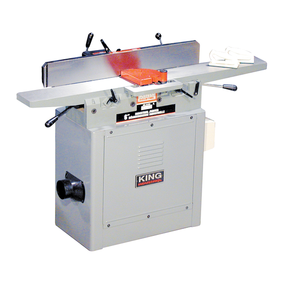
6” & 8” INDUSTRIAL JOINTERS MODEL: KC-70FX (6” Jointer) MODEL: KC-80FX (8” Jointer) INSTRUCTION MANUAL COPYRIGHT © 2002 ALL RIGHTS RESERVED BY KING CANADA TOOLS INC. - Page 2 IMPORTANT INFORMATION 2-YEAR KING CANADA TOOLS LIMITED WARRANTY OFFERS A 2-YEAR LIMITED WARRANTY FOR EITHER 6” OR 8” JOINTER FOR INDUSTRIAL USE. PROOF OF PURCHASE Please keep your dated proof of purchase for warranty and servicing purposes. REPLACEMENT PARTS Replacement parts for this tool are available at our authorized KING CANADA service centers across Canada. For servicing, contact or return to the retailer where you purchased your product along with your proof of purchase.
-
Page 3: General Safety Instructions
GENERAL SAFETY INSTRUCTIONS 1. KNOW YOUR TOOL 12. ALWAYS WEAR SAFETY GLASSES. Read and understand the owners manual and labels affixed to the Always wear safety glasses (ANSI Z87.1). Everyday eyeglasses tool. Learn its application and limitations as well as its specific only have impact resistant lenses, they are NOT safety glasses. -
Page 4: Electrical Connections
SERIOUS INJURY! ALL ADJUSTMENTS OR REPAIRS MUST BE DONE WITH THE MACHINE DISCONNECTED FROM THE POWER SOURCE. FAILURE TO COMPLY MAY RESULT IN SERIOUS INJURY! KC-70FX POWER SUPPLY WARNING: YOUR KC-70FX (6” Jointer) MUST BE CONNECTED PROPERLY GROUNDED OUTLET TO A 120V, 15-AMP, BRANCH CIRCUIT AND USE A 15-AMP TIME DELAY FUSE OR CIRCUIT BREAKER. -
Page 5: Unpacking And Assembly
UNPACKING & ASSEMBLY UNPACKING AND CLEANING THE JOINTER Carefully unpack the jointer and all loose items from the carton. Remove the protective coating from the machined surfaces of the jointer. This coating may be removed with a soft cloth moistened with kerosene ( do not use acetone, gasoline, or lacquer thinner for this purpose). - Page 6 ASSEMBLY ASSEMBLING FENCE..3. Assemble the fence (G) Fig. 8, with the pivot brackets (H) to the sliding bracket (B) using the two 1-3/16” long socket head cap screws (F) which were removed in STEP 2. FIGURE 8 ASSEMBLING RABBETING LEDGE Assemble the rabbeting ledge (A) Fig.
- Page 7 ASSEMBLY ASSEMBLING BELT, ALIGNING PULLEYS To assemble the drive belt proceed as follows: 1. Place the belt (A) Fig. 12, around the cutterhead pulley (B), pass it through the hole in jointer stand and around the motor pulley (C) as shown. 2.
-
Page 8: Operating Controls
OPERATING CONTROLS & ADJUSTMENTS FENCE OPERATION The fence can be moved across the table by loosening lock lever (A) Fig. 14, sliding the fence (B) to the desired position and retightening the locking lever (A). As the fence is moved across the table, the sliding bracket (C) guards the cutterhead in back of the fence. - Page 9 OPERATING CONTROLS & ADJUSTMENTS ADJUSTING FENCE POSITIVE STOPS The fence on the jointer is equipped with positive stops at 90 degrees and 45 degrees right and left. 90 DEGREE POSITIVE STOP To check the accuracy of the positive stops, position the fence at 90 degrees to the table by making certain the end of index pin (A) Fig.
- Page 10 OPERATING CONTROLS & ADJUSTMENTS 45 DEGREE OUTWARD POSITIVE STOP To check the accuracy of the positive stops at the 45 degree outward angle of tilt, position the fence (E) Fig. 22, outward as far as possible. Use a combination square (D) and check to see if the fence is tilted outward accurately at 45 degrees.
-
Page 11: Adjusting, Replacing Knives
ADJUSTING, REPLACING KNIVES REMOVING, REPLACING AND RESETTING KNIVES If the knives are removed from the cutterhead for replacement or regrinding, care must be used in removing and replacing them as follows: 1. DISCONNECT THE MACHINE FROM THE POWER SOURCE. 2. Be extremely careful that your hands do not come in contact with the cutterhead.
Need help?
Do you have a question about the KC-70FX and is the answer not in the manual?
Questions and answers