
Related Manuals for King Industrial KC-12HJPC


Summary of Contents for King Industrial KC-12HJPC
-
Page 1: Instruction Manual
12” INDUSTRIAL JOINTER/PLANER WITH SPIRAL CUTTERHEAD INSTRUCTION MANUAL MODEL: KC-12HJPC COPYRIGHT © 2017 ALL RIGHTS RESERVED BY KING CANADA TOOLS INC. -
Page 2: Warranty Information
WARRANTY INFORMATION 2-YEAR kING CANADA TOOLS LIMITED WARRANTY OFFERS A 2-YEAR LIMITED WARRANTY FOR THIS 12” INDUSTRIAL JOINTER/PLANER INTENDED FOR NON COMMERCIAL USE PROOF OF PURCHASE Please keep your dated proof of purchase for warranty and servicing purposes. PARTS DIAGRAM & PARTS LISTS Refer to the Parts section of the King Canada web site for the most updated parts diagram and parts list. -
Page 3: Safety Rules
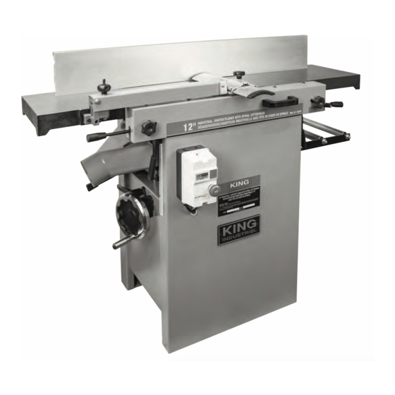
GENERAL & SPECIFIC SAFETY RULES 1. kNOW YOUR TOOL footwear is recommended. Wear protective hair covering to Read and understand the owners manual and labels affixed to the contain long hair. Roll up long sleeves above the elbows. 12. ALWAYS WEAR SAFETY GLASSES. tool. - Page 4 20) Planer power feed lever 9) Planer outfeed roller support 21) Planer table (infeed side) 10) Jointer table lock levers (1 of 2) 11) Magnetic switch (On/Off) Specifications MODEL kC-12HJPC Maximum jointing/planing width 12” Maximum depth of cut 1/8” Spiral cutterhead speed 6,500 RPM Spiral cutterhead diameter 2-3/4”...
-
Page 5: Electrical Information
ELECTRICAL INFORMATION WARNING! ALL ELECTRICAL CONNECTIONS MUST BE DONE BY A QUALIFIED ELECTRICIAN. FAILURE TO COMPLY MAY RESULT IN SERIOUS INJURY! ALL ADJUSTMENTS OR REPAIRS MUST BE DONE WITH THE MACHINE DISCONNECTED FROM THE POWER SOURCE. FAILURE TO COMPLY MAY RESULT IN SERIOUS INJURY! POWER SUPPLY MAGNETIC SWITCH AND EMERGENCY STOP bUTTON WARNING: YOUR JOINTER/PLANER MUST BE CONNECTED TO A... - Page 6 UNPACkING, ASSEMbLY & ADJUSTMENTS UNPACkING AND CLEANUP WARNING! TO REDUCE THE POTENTIAL FOR PERSONAL INJURY AND/OR DAMAGE TO THE MACHINE, BEFORE ASSEMBLING MAKE SURE THE MACHINE IS TURNED OFF. DO NOT TURN ON THE MACHINE UNTIL INSTRUCTED TO DO SO AFTER ALL ASSEMBLY STEPS IN THIS MANUAL HAVE BEEN COMPLETED.
- Page 7 ADJUSTMENTS & OPERATION PLANER MODE 1. Using the Power Feed Handle: The power feed handle (A) Fig.7 in the downward position is set to “OFF” (Jointer mode). To turn the power feed “ON” for Planer mode, pull the power feed handle to the left and then lift it up as shown.
- Page 8 ADJUSTMENTS & OPERATION TAbLE ADJUSTMENTS In order for proper jointing operation, the infeed and outfeed tables must be coplanar. This means that the infeed and outfeed tables are set along the same plane, forming a perfectly flat surface. If the tables are not coplanar, the workpiece could be slightly tapered or twisted after jointing.
- Page 9 ADJUSTMENTS & OPERATION ROTATING/CHANGING CUTTERHEAD CUTTER INSERTS WARNING! When checking cutter inserts, always make sure the machine is disconnected from the power source. Two T25 Torx bit screwdrivers are supplied with this machine to remove or adjust the position of the cutter inserts secured in the cutterhead. The spiral cutterhead is equipped with 60 indexable cutter inserts (15mm x 15mm x 2.5mm accessory model KW-104) which can be rotated to reveal one of its four cutting edges.
-
Page 10: Feed Roller Height Adjustment
ADJUSTMENTS & OPERATION FEED ROLLER HEIGHT ADJUSTMENT The feed rollers are set at the factory, and shouldn’t require adjustment. However, if the feed rollers do need to be adjusted: 1. Disconnect the machine from the power source. 2. Remove the front cutterhead access panel (A) Fig.18 and the back access panel (B) by removing the four round head allen screws (C). -
Page 11: Operation
OPERATION CONNECTING TO A DUST COLLECTOR This machine is equipped with a dust chute for use during jointing and planing operations. The dust chute (A) Fig.22 has a 4” opening. It’s very important to use some type of dust collection system with this machine to prevent the build up of wood chips that could interfere with the rollers or the cutterhead. -
Page 12: Operation And Maintenance
OPERATION & MAINTENANCE USING THE MACHINE IN PLANER MODE continued... 6. The wider the workpiece, the shallower the depth of cut should be. The harder the wood, the shallower the depth of cut should be. 7. Avoid wood with knots. These can come dislodged during planing and cause damage and/or injury. 8. -
Page 13: Regular Maintenance Checklist
MAINTENANCE MAINTENANCE bELT REPLACEMENT Replacing the Planer Feed Roller Drive belt: NOTE: The cutterhead drive belt must be removed first in order to replace the planer feed roller drive belt. 7. Move the power feed handle into the down position, releasing tension on the belt.
Need help?
Do you have a question about the KC-12HJPC and is the answer not in the manual?
Questions and answers