
Related Manuals for King Industrial KC-351S


Summary of Contents for King Industrial KC-351S
- Page 1 3/4” INDUSTRIAL WOODWORKING SHAPER MODEL: KC-351S INSTRUCTION MANUAL COPYRIGHT © 2006 ALL RIGHTS RESERVED BY KING CANADA TOOLS INC.
- Page 2 IMPORTANT INFORMATION 2-YEAR KING CANADA TOOLS LIMITED WARRANTY OFFERS A 2-YEAR LIMITED WARRANTY FOR THIS INDUSTRIAL WOODWORKING SHAPER FOR INDUSTRIAL USE. PROOF OF PURCHASE Please keep your dated proof of purchase for warranty and servicing purposes. REPLACEMENT PARTS Replacement parts for this tool are available through our authorized KING CANADA service centers across Canada. For servicing, contact or return to the retailer where you purchased your product along with your proof of purchase.
- Page 3 GENERAL & SPECIFIC SAFETY INSTRUCTIONS 1. KNOW YOUR TOOL footwear is recommended. Wear protective hair covering to Read and understand the owners manual and labels affixed to the contain long hair. Roll up long sleeves above the elbows. 12. ALWAYS WEAR SAFETY GLASSES. tool.
- Page 4 220V Plug A 220V plug is not supplied with this shaper and must be purchased at WARNING: YOUR KC-351S (220V) MUST BE CONNECTED TO A your local hardware store. The 220V plug must be a CSA listed plug suitable for 220V operation. This plug is illustrated in Fig.2. Contact 220V, 20-AMP, BRANCH CIRCUIT.
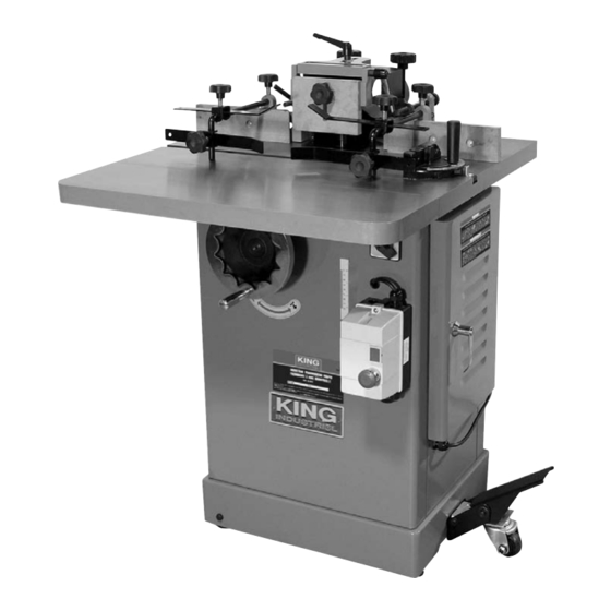
- Page 5 GETTING TO KNOW YOUR SHAPER & UNPACKING GETTING TO KNOW YOUR SHAPER 1) Extension table 2) Hold-down 3) Hold-down lock knob 4) Hold-down support lock knob 5) Fence adjusting ratchet 6) Adjustable front guard 7) Front guard casting lock knob 8) 4”...
- Page 6 ASSEMBLY AFTER UNPACKING Assembling Extension Table The cast iron extension table extends your work surface area to provide support for larger workpieces. Follow the instructions below to ensure your extension table is flush and level with the shaper work table. 1) Make sure the contact surfaces are clean, free of dirt or grit.
- Page 7 ADJUSTMENTS & OPERATION WARNING! ALL ADJUSTMENTS MADE TO THIS SHAPER MUST Resurfacing the Fence BE DONE WITH THE POWER CORD DISCONNECTED FROM THE POWER SOURCE. Occasionally the fence assembly needs resurfacing to ensure that the fence is parallel with itself and square with the table. Adjusting the Fence Assembly Align one or both fence halves so they are in close alignment.
- Page 8 ADJUSTMENTS & OPERATION Changing Spindles This shaper comes with a 1/2” and 3/4” spindle assemblies as standard accessories. Please note that 1” (model: KW-088) and 1-1/4” (model: KW-089) spindle assemblies are available as optional accessories. A spindle assembly (A) gets locked in a tapered seat (B) Fig.10 at the top of the spindle housing and is held in place with a threaded draw bar (C) and draw bar nut (D) below the spindle housing (B) Fig.11.
- Page 9 ADJUSTMENTS & OPERATION 1) Rub Collar below the cutter (Fig.13) When a rub collar is used below the cutter, pay attention to any unintentional movement which may lift the workpiece into the cutter, damaging your work and creating an unsafe situation. Spindle Spindle nuts Cutter...
- Page 10 ADJUSTMENTS & OPERATION Adjusting Table Inserts This shaper comes with 3 table inserts (A) Fig.16 which give you four possible opening diameters in the shaper table surface. Use the smallest opening that a particular cutter will allow. This offers more support for the workpiece and reduces the amount of chips that can fall down into the machine.
-
Page 11: Operation And Maintenance
OPERATION & MAINTENANCE Magnetic Switch and Forward/Reverse Switch Operation To turn the shaper on, press the ON button (A) Fig.20 on the magnetic switch (C), to turn the shaper off, press the OFF button (B) on the magnetic switch (C). This shaper also comes with a forward/reverse switch (D) which controls the direction of rotation of the spindle.
Need help?
Do you have a question about the KC-351S and is the answer not in the manual?
Questions and answers