
Subscribe to Our Youtube Channel
Related Manuals for King Industrial KC-119FC-LS


Summary of Contents for King Industrial KC-119FC-LS
-
Page 1: Instruction Manual
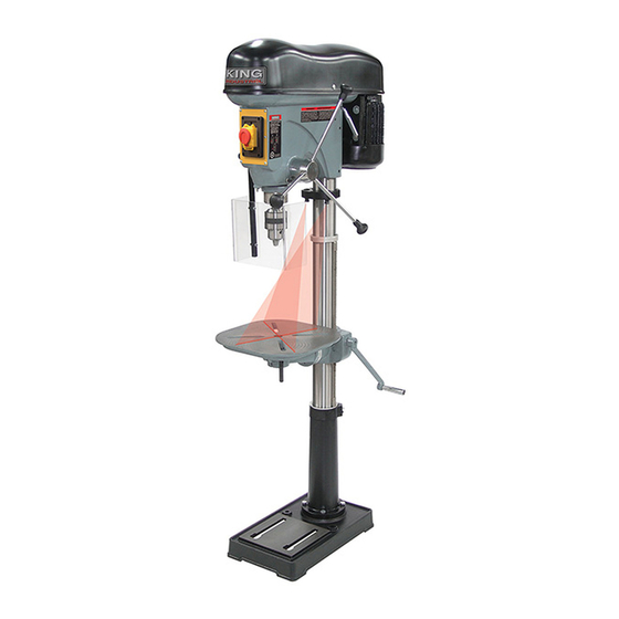
17” LONG STROKE DRILL PRESS WITH SAFETY GUARD 01/2017 Line Interruption INSTRUCTION MANUAL MODEL: KC-119FC-LS COPYRIGHT © 2016 ALL RIGHTS RESERVED BY KING CANADA TOOLS INC. -
Page 2: Warranty Information
WARRANTY INFORMATION 2-YEAR KING CANADA TOOLS LIMITED WARRANTY OFFERS A 2-YEAR LIMITED WARRANTY FOR THIS 17” DRILL PRESS FOR NON-COMMERCIAL USE. PROOF OF PURCHASE Please keep your dated proof of purchase for warranty and servicing purposes. REPLACEMENT PARTS Replacement parts for this product are available at our authorized King Canada service centers across Canada. LIMITED TOOL WARRANTY King Canada makes every effort to ensure that this product meets high quality and durability standards. -
Page 3: General Safety Instructions For Power Tools
GENERAL SAFETY INSTRUCTIONS FOR POWER TOOLS 1. KNOW YOUR TOOL footwear is recommended. Wear protective hair covering to con- tain long hair. Roll up long sleeves above the elbows. Read and understand the owners manual and labels affixed to the 12. -
Page 4: Electrical Information
ELECTRICAL INFORMATION WARNING ALL ELECTRICAL CONNECTIONS MUST BE DONE BY A QUALIFIED ELECTRICIAN. FAILURE TO COMPLY MAY RESULT IN SERIOUS INJURY! ALL ADJUSTMENTS OR REPAIRS MUST BE DONE WITH THE MACHINE DISCONNECTED FROM THE POWER SOURCE. FAILURE TO COMPLY MAY RESULT IN SERIOUS INJURY! POWER SUPPLY TURNING THE DRILL PRESS ON/OFF WARNING: YOUR DRILL PRESS MUST BE CONNECTED TO A 120V... -
Page 5: Getting To Know Your Drill Press
18. Depth stop rod with depth scale 19. Table support lock handle 20. Column and rack locking collar 21. Locking set screw (1 of 2) FIGURE 4 SPECIFICATIONS MODEL....................................KC-119FC-LS VOLTAGE ..............................110V/220V (prewired 110V) AMPS ....................................12.5A/6.25A MOTOR R.P.M....................................1725 Hz/PHASE..................................60 Hz / 1 PHASE CHUCK CAPACITY ..................................3/4”... - Page 6 ASSEMBLY bASE, COLUMN & TAbLE ASSEMbLY 1) Position the base (A) Fig.6 on the floor. Remove the protective covering and discard. 2) Remove protective sleeve from the column & column support (B) and discard. Place the column assembly on the base, align the holes in the column support with the holes in the base.
-
Page 7: Installing The Head
ASSEMBLY bASE, COLUMN & TAbLE ASSEMbLY continued... 9) Locate the crank handle (A) Fig.9 and install it on the worm gear shaft on the side of the table support. Tighten the hex. bolt (B) on the flat section of the worm gear shaft. 10) Install the table support lock handle (C) Fig.9 to the table support as shown. - Page 8 ASSEMBLY INSTALLING PULLEY COVER KNOb OR LOCKING PULLEY COVER 1) For safety reasons, user may be required to lock the pulley cover (B) Fig.12 to prevent easy access to the pulleys. This can be done by using the small pan head screw (A) which came installed. 2) If safety is less of a concern, you can install the lock knob (C) Fig.12 to the pulley cover (B) instead.
-
Page 9: Assembly And Adjustments
ASSEMBLY & ADJUSTMENTS INSTALLING AND USING THE LIMIT SWITCH PROTECTED SAFETY GUARD continued... 2) Remove cap screw (A) Fig.15 from the bar and safety guard assembly (B). 3) Slide the bar and safety guard assembly (B) up into the limit switch bracket (C). - Page 10 ASSEMBLY & ADJUSTMENTS INSTALLING DUAL LASER GUIDE ATTACHMENT WARNING! Do not look directly at the laser beams. Do not aim the laser beams at any person or any object other than your workpiece. NOTE: This dual laser guide attachment supplied with this drill press is universal, 4 different mounting brackets are supplied.
-
Page 11: Hole Location
ADJUSTMENTS & OPERATION ADJUSTING THE TAbLE SqUARE TO THE HEAD 1) Insert a precision round steel rod (A) Fig.21 approximately 3” long into the chuck and tighten. 2) With the table (B) raised to working height and locked into position, place a combination square (C) flat on the table beside the rod. -
Page 12: Maintenance & Troubleshooting
MAINTENANCE / TROUBLESHOOTING MAINTENANCE WARNING! For your own safety, turn the switch “OFF” and remove the plug from the power source before maintaining or lubricating your drill press. • Keep the Drill Press clean and free of dust and debris. Painted surfaces can be wiped with a damp rag.
Need help?
Do you have a question about the KC-119FC-LS and is the answer not in the manual?
Questions and answers