
Subscribe to Our Youtube Channel
Related Manuals for King Industrial KC-15HS-VS


Summary of Contents for King Industrial KC-15HS-VS
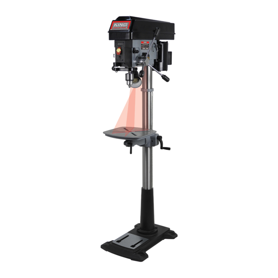
- Page 1 15” VARIABLE SPEED FLOOR DRILL PRESS MODEL: KC-15HS-VS INSTRUCTION MANUAL COPYRIGHT © 2020 ALL RIGHTS RESERVED BY KING CANADA TOOLS INC.
-
Page 2: Warranty Information
WARRANTY INFORMATION 2-YEAR KING CANADA TOOLS LIMITED WARRANTY OFFERS A 2-YEAR LIMITED WARRANTY FOR THIS 15” DRILL PRESS FOR NON-COMMERCIAL USE. PROOF OF PURCHASE Please keep your dated proof of purchase for warranty and servicing purposes. REPLACEMENT PARTS Replacement parts for this product are available at our authorized King Canada service centers across Canada. Please use the 10 digit part numbers listed in this manual for all part orders where applicable. -
Page 3: General Safety Instructions For Power Tools
GENERAL SAFETY INSTRUCTIONS FOR POWER TOOLS 1. KNOW YOUR TOOL 12. ALWAYS WEAR SAFETY GLASSES. Read and understand the owners manual and labels affixed to Always wear safety glasses (ANSI Z87.1). Everyday eye-glasses the tool. Learn its application and limitations as well as its specific only have impact resistant lenses, they are NOT safety glasses. -
Page 4: Electrical Information
ELECTRICAL INFORMATION WARNING ALL ELECTRICAL CONNECTIONS MUST BE DONE BY A QUALIFIED ELECTRICIAN. FAILURE TO COMPLY MAY RESULT IN SERIOUS INJURY! ALL ADJUSTMENTS OR REPAIRS MUST BE DONE WITH THE MACHINE DISCONNECTED FROM THE POWER SOURCE. FAILURE TO COMPLY MAY RESULT IN SERIOUS INJURY! POWER SUPPLY WARNING: YOUR DRILL PRESS MUST BE CONNECTED TO A 120V WALL OUTLET, WITH A MINIMUM 15-AMP. -
Page 5: Getting To Know Your Drill Press
15. Speed range setting belt 16. Flexible worklight w/ LED bulb 17. Laser guide (1 of 2) 18. Mechanical variable speed adjusting lever 19. Depth stop FIGURE 4 SPECIFICATIONS MODEL KC-15HS-VS Capacity 5/8” Chuck size 5/8” Swing 15” Max. distance chuck to column 7-1/2”... - Page 6 ASSEMBLY BASE, COLUMN & TABLE ASSEMBLY 1) Position the base (A) Fig.6 on the floor. Remove the protective covering and discard. 2) Remove protective bag from the column, column support and table support assembly (B) and discard. Place the column assembly on the base, align the holes in the column support with the holes in the base.
- Page 7 ASSEMBLY INSTALLING THE HEAD Warning! The drill press head is very heavy, it is not recommended to attempt installation of the head by yourself, obtain help. 1) Carefully lift the head (A) Fig.9 above the column (B) and slide it down on the column as far as it will go. Align the head with the table and the base.
-
Page 8: Assembly And Adjustments
ASSEMBLY & ADJUSTMENTS INSTALLING A DRILL BIT IN THE 5/8” CHUCK 1) Insert the chuck key (A) Fig.13 into the chuck (B) as shown, turn chuck key counterclockwise to open the chuck jaws. 2) Insert a drill bit (C). 3) Tighten the chuck key clockwise to secure the drill bit in the chuck. Note: This drill press comes with a convenient chuck key holder (D) Fig.13. - Page 9 ADJUSTMENTS & OPERATION USING AND ADJUSTING DUAL LASER GUIDES Warning! Do not look into the direct or reflected laser beam; can cause eye injury up to 50 feet (15m) away. Class 2 lasers are considered safe for accidental eye exposure. Do not look or stare into laser beam. This is not a toy.
- Page 10 ADJUSTMENTS & OPERATION CHANGING SPEED RANGE (LOW/HIGH) This drill press has 2 variable spindle speed ranges. Low range from 280 to 1100 RPM and high range from 900-3300 RPM. To change the spindle speed range: WARNING! Always disconnect the Drill Press from the power source before attempting to change the speed range (adjusting position of the belt).
-
Page 11: Operation And Maintenance
OPERATION & MAINTENANCE OPERATION TURNING DRILL PRESS ON/OFF The On/Off switch (A) Fig.24 comes with a removable safety key (B). When the safety key is removed from the switch and placed in a safe location, unauthorized persons or children can’t turn the switch to the On position.
Need help?
Do you have a question about the KC-15HS-VS and is the answer not in the manual?
Questions and answers