Advertisement
EC90A-AL Installation Guide
• One EC90A-AL system unit
• Mounting screws for SATA drive
• Mounting screws for Mini PCIe module
• 1 Quick Installation Guide
• 1 CD disk includes:
- Drivers / Manual
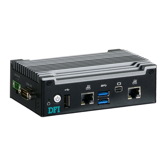
Front View
DC-in
Bottom View
DFI reserves the right to change the specifications at any time prior to the product's release. For the latest revision and details of the
installation process, please refer to the user's manual.
Package Contents
Panel
HDD LED
Status LED
(green)
LAN 1
Reset
USB 2.0
COM 1 /DIO
www.dfi.com
Mini-DP
USB 3.0
LAN 2
Top View
1
2-pin Switch
Advertisement
Table of Contents

Related Manuals for DFI EC90A-AL


Summary of Contents for DFI EC90A-AL
- Page 1 COM 1 /DIO 2-pin Switch Top View Bottom View DFI reserves the right to change the specifications at any time prior to the product's release. For the latest revision and details of the installation process, please refer to the user's manual. www.dfi.com...
- Page 2 Removing the Chassis Cover Please observe the following guidelines and follow the procedure to open the system. 1. Make sure the system and all other peripheral devices connected to it have been powered off. 2. Disconnect all power cords and cables. 3.
- Page 3 4. Lift the cover to open the system. The Mini PCIe socket is readily accessible after removing the chassis cover. Mini PCIe socket...
- Page 4 Installing a Mini PCIe Card The system board is equipped with 1 Mini PCIe slot that supports PCIe and USB signals. 1. Grasp the Mini PCIe card by its edges and align the notch in the connector of the PCIe card with the notch in the connector on the system board. Insert the bottom edge of the card into the socket.
- Page 5 DIN-Rail Mount The system features DIN-rail mount chassis that facilitates fast installation of the EC90A-AL to a DIN rail. The din-rail mount kit includes the following: • Din-rail mount bracket • 2 screws 1. Use the provided mounting screws to attach the din-rail mount bracket to the rear side of the device.
- Page 6 Wall Mount The wall mount kit includes the following: • Two wall mount brackets • Bracket screws 1. Align the mounting holes of the wall mount bracket with the screw holes of the system and use the provided mounting screws to secure the wall mount brackets on both sides of the system.
- Page 7 The following diagrams show the location and dimension of the wall moutning holes.
- Page 8 1-2, 4-5, 7-8, 10-11 On 10-11 On 2-3, 5-6, 8-9, 2-3, 5-6, 8-9, 11-12 On 11-12 On Note: You cannot use the external COM Port 1 and DIO at the same time. Please set JP1 and JP2 together. www.dfi.com A50001823...
Need help?
Do you have a question about the EC90A-AL and is the answer not in the manual?
Questions and answers