Advertisement
Quick Links
EC531-KH/EC532-KH Installation Guide
• 1 EC531-KH/EC532-KH system unit
• 1 Quick Installation Guide
• 1 CD disk includes:
- Drivers / Manual
Front View
DIO COM6 COM7 COM8
Line-out
Microphone
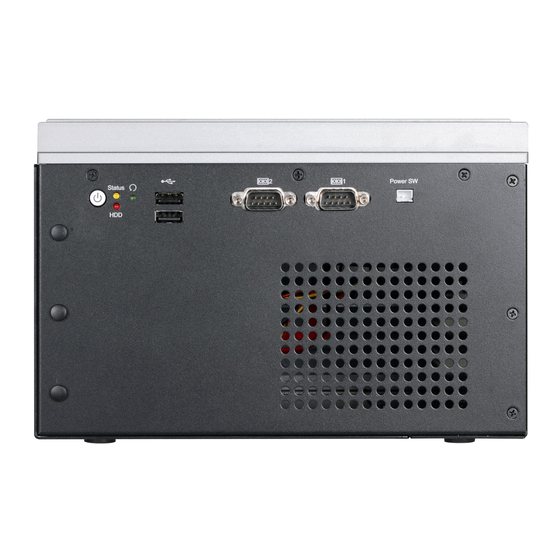
Rear View
USB 2.0
Power Button
Status LED
HDD LED
Reset Switch
Notes:
1.
This port can be in HDMI or DVI-D (DVI available upon request).
2.
This port is a DP/HDMI combo port but can only transmit either HDMI or DP signals (as indicated on
the panel). Please plug in a DP or an HDMI cable with the right orientation and alignment to avoid
damage to the connector. You should feel resistance (due to a pin on the right) if the cable is not
inserted correctly. For detailed instructions, see https://youtu.be/SUj07rfN5l8.
DFI reserves the right to change the specifications at any time prior to the product's release. For the latest revision and details of the
installation process, please refer to the user's manual.
Package Contents
HDMI
(1)
DVI-I
(DVI-D signal)
DC-in
Expansion slots
1
(2)
USB 3.0
LAN 1 LAN 2
SATA 1 SATA 2
USB 3.0
VGA
COM 3
COM 4
COM 5
Remote Power Switch
COM 2 COM 1
www.dfi.com
Advertisement

Subscribe to Our Youtube Channel
Related Manuals for DFI EC531-KH


Summary of Contents for DFI EC531-KH
- Page 1 You should feel resistance (due to a pin on the right) if the cable is not inserted correctly. For detailed instructions, see https://youtu.be/SUj07rfN5l8. DFI reserves the right to change the specifications at any time prior to the product's release. For the latest revision and details of the www.dfi.com...
- Page 2 Installing a 2.5" SATA Drive The SATA drive bay can be easily accessed witout opening the system. However, the system does not support hot-swapping hard drives; turn off the system first before proceeding with the following procedure for installing a SATA drive. Locate the drive bay on the front panel and open it by releasing the handle.
-
Page 3: Installing A Sodimm
Installing a SODIMM 1. The SODIMM sockets are located on the system board. You need to revmove the system cover first. Before working inside your system, observe the following precautions: (1) Make sure the system and all other peripherals connected to it have been powered off. - Page 4 To install a SODIMM module, grasp the module by its edges and align the module’s notch with the socket’s notch; then insert the module into the socket at an angle and push it down until you feel a click. SODIMM module Notes: The system supports dual-channel configuration.
-
Page 5: Installing A Mini Pcie Card
Installing a Mini PCIe Card The system board is equipped with 2 Mini PCIe slots with Mini SIM card sockets to support a variety of wireless LAN and mobile broadband communication modules. Mini PCIe slot 1 provides both USB and PCIe interfaces whereas Mini PCIe slot 2 provides only USB interface. - Page 6 Installing a SIM Card Open the SIM card socket by pushing the white latch inward. SIM 2 Push the latch inward to open it Insert the SIM card into the slot. Please place the card with the IC facing down and the angled corner aligning with the socket's angled corner so it will be cor- rectly in contact with the system board.
-
Page 7: Installing An M.2 Card
Installing an M.2 Card The onboard M.2 Type 2280 connector (M Key) supports PCIe NVMe modules up to PCIe Gen 3.0 x4 bandwidth. Note that only SKUs with Intel QM175 Chipset support M.2 socket. ® M.2 Slot To install an M.2 card, insert the bottom edge of the M.2 card into the connector, and then secure the card to the standoff with the provided mounting screw. - Page 8 Installing a PCI or PCIe Expansion Card Important: When inserting expansion cards into the system unit, please select a standard card within 190mm (as shown in the picture below) in order to fit expansion slots. 1. PCI and PCIe slots on the riser card inside the system are used to install expansion cards.
- Page 9 PCIe card Rear View Note: The EC531-KH has one PCIe x16 slot and two PCI slots with the H320-2P1E card, whereas the EC532-KH has one PCI slot and two PCIe x16 slots with the H320-1P2E card.
-
Page 10: Board Layout And Jumper Settings
Board Layout and Jumper Settings Clear CMOS Data (JP1) Front Panel Front Audio PS/2 Power Select (JP4) (JP14) DIO Power Power Button Buzzer USB 2.0 DDR4_2 SODIMM USB 9 Power LED USB 2.0 HDD LED USB 13/14 COM 5 DDR4_1 SODIMM SPI Flash Reset GLAN 2... - Page 11 I/O board COM8 COM6 COM7 DC-in USB 5-6 USB 7-8 USB 3.0 (JP7) (JP3) (JP2) (JP1) (JP5) (JP6) (JP4) (JP11) (JP9) (JP10) (JP8) (JP13) (JP14) (JP12) RS232/Power Select: RS232/422/485 Select: COM 8 (JP12) COM 6 (JP7), COM 7 (JP11) RS232 (default) 1-3 (RI), 2-4 (DCD) On RS232 (default) 1-2 On...
Need help?
Do you have a question about the EC531-KH and is the answer not in the manual?
Questions and answers