Advertisement
EC500-SD Installation Guide
• 1 EC500-SD system unit
• Mounting screws for SATA drive
• Mounting screws for Mini PCIe module
Power Button
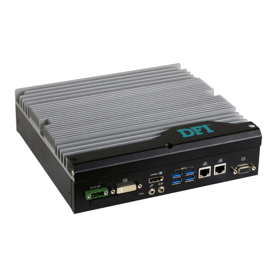
Front View
Remote power
Rear View
Notes:
1. Please gently press the power button to avoid possible damages.
2. The HDMI is a DP/HDMI combo port but can only provide HDMI connectivity (unless wired as a DP
port by request). Please plug in an HDMI cable with the right orientation and alignment to avoid
damage to the connector. You should feel resistance (due to a pin on the right) if the cable is not
inserted correctly. For detailed instructions, please see a video at https://youtu.be/SUj07rfN5l8.
Aligning side
(left)
DFI reserves the right to change the specifications at any time prior to the product's release. For the latest revision
and details of the installation procedure, please refer to the user's manual.
Package Contents
Panel
(1)
Status LED
HDD LED
USB 2.0
COM 2
on/off
Reset Button
DVI-I
DC-in
(DVI-D Signal)
HDMI
CFast
Microphone
Line-out
Angled-corner
pin
1
www.dfi.com
COM 1
COM 3
USB 3.0
LAN 1
LAN 2
Angled-corner
(up)
COM 4
VGA
Align this edge with the
left side of the connector
Advertisement
Table of Contents

Related Manuals for DFI EC500-SD


Summary of Contents for DFI EC500-SD
- Page 1 (left) (up) DFI reserves the right to change the specifications at any time prior to the product's release. For the latest revision and details of the installation procedure, please refer to the user's manual. www.dfi.com...
-
Page 2: Removing The Chassis Cover
Removing the Chassis Cover Make sure the system and all other peripherals connected to it have been powered off. Disconnect all power cords and cables. The 6 mounting screws on the left side, right side and bottom of the system are used to secure the cover to the chassis. - Page 3 Lift the cover upward to open the system. The SODIMM sockets, Mini PCIe slot and SATA drive bay are accessible after removing the chassis cover. SATA drive bay Mini PCIe slot SODIMM socket...
-
Page 4: Installing A Sodimm
Installing a SODIMM The SODIMM sockets are located on the system board. Remove the SATA drive bay to access the SODIMM sockets. Mounting screw SATA drive bay SODIMM socket... - Page 5 Grasp the module by its edges and align the memory’s notch with the socket’s notch; then insert the memory into the socket at an angle and push it down until you feel a click. SODIMM module Notes: The system supports dual-channel configuration. To enable dual-channel, populate both SODIMM sockets.
- Page 6 Installing a 2.5” SATA Drive Before installing the SATA drive, connect the SATA data and power cable to the SATA data connector of the SATA drive. Then install the SATA drive on the HDD bracket with the provided mounting screws from the HDD drive bay kit. Mounting screw Mounting Screws SATA data and power cable...
- Page 7 Connect the other end of the SATA data and power cable to the SATA data and power connectors on the system board respectively. SATA power connector SATA data connector...
-
Page 8: Installing A Cfast Card
Installing a CFast Card Before installing a CFast card, take off the CFast card slot cover. CFast slot cover Gently insert the CFast card straight with the label on the CFast card facing up until you feel it lock into place. Do not force the card into the slot if the card is not correctly inserted. Close the CFast card cover. - Page 9 Installing a Mini PCIe or mSATA Card The system board is equipped with 2 Mini PCIe slots: one full-size and one half-size slot. Here we will demonstrate the installation of a full-size Mini PCIe card. Grasp the Mini PCIe card by its edges and align the notch in the connector of the Mini PCIe card with the notch in the connector on the system board.
-
Page 10: Board Layout And Jumper Settings
2. When COM2 RS232/422/485 is selected, JP7 and JP14 must be set in accordance to JP13. 3. When COM3 RS232/422/485 is selected, JP8 and JP15 must be set in accordance to JP9. 4. When COM4 RS232/422/485 is selected, JP10 and JP16 must be set in accordance to JP4. www.dfi.com A45112945...
Need help?
Do you have a question about the EC500-SD and is the answer not in the manual?
Questions and answers