
Related Manuals for DFI VC230-AL


Summary of Contents for DFI VC230-AL
- Page 1 VC230-AL In-Vehicle Box PC User’s Manual Preliminary Preliminary Version Version A-545-M-2019...
- Page 2 1. The changes or modifications not expressly approved by the party responsible for com- pliance could void the user’s authority to operate the equipment. 2. Shielded interface cables must be used in order to comply with the emission limits. User's Manual | VC230-AL...
-
Page 3: Table Of Contents
POWER OFF Delay Time Select ..................20 Remote Switch High/Low Active (JP2) ...............20 I/O Ports (System Board) ....................21 Graphics Display ......................21 USB Ports ........................21 RJ45 LAN Ports ......................22 COM (Serial) Port ......................22 Speaker ...........................23 Front Audio ........................23 12V DC-In ........................24 User's Manual | VC230-AL... - Page 4 The system and accessories in the package may not come similar to the information listed above. This may differ in accordance with the sales region or models in which it was sold. For more information about the standard package in your region, please contact your dealer or sales representative. User's Manual | VC230-AL...
-
Page 5: Chapter 1 - Introduction
Make sure the system is placed or mounted correctly and stably to prevent the chance of dropping or falling may cause damage. • The openings on the system shall not be blocked and shall be kept in distance from User's Manual | VC230-AL... -
Page 6: Ddr4
1 x Reset Button resemble your actual products. Please visit the download page at go.dfi. com/VC230-AL, or via the QR code to the right for the latest datasheet. Audio 1 x Speaker Out with Dual 5w Amp User's Manual | VC230-AL... -
Page 7: Chapter 2 - Hardware Installation
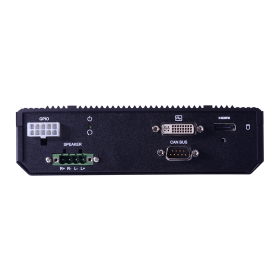
Front Panel GPS Antenna COM 1 USB 2.0 LAN 1 LAN 2 Vehicle Power and Ignition Bottom Remote Antenna USB 3.0 Switch Hole Rear Panel Power LED Dimensions & Reset GPIO HDMI SSD LED Speaker CAN BUS User's Manual | VC230-AL... -
Page 8: Wall Mount
Locate 192.00 the mounting holes on the bottom of the system as shown in the photo. Screw on 182.20 the two brackets onto the system with four screws as illustrated below. 192.00 User's Manual | VC230-AL 182.20... -
Page 9: Assembly
Please make sure the brackets are oriented correctly as illustrated. The two brackets shall perfectly mirror each other. The handles shall be Bottom closer to the SO-DIMM socket on the mother board. Side Side Mounting Screw Holes User's Manual | VC230-AL... -
Page 10: Top Cover
M3*6 spring screws tight as shown below. The top cover is secured onto the system board's brass stand-offs at four corners. Front Panel a n e n t P F r o Rear Panel User's Manual | VC230-AL... -
Page 11: Front And Rear Panels
Front and Rear Panels The front and rear panels are secured onto the system board via the I/O stand-offs and screws as shown below. Front Panel Rear Panel User's Manual | VC230-AL... -
Page 12: Antenna
Connect the internal cable to the board's antenna connector, screw the antenna connector through the antenna hole on the front panel with washers and nuts, and screw on the antenna as illustrated below. Board Connector Cable Antenna Connector Washer Antenna Chassis Wall User's Manual | VC230-AL... -
Page 13: Board Layout
If a wrist strap is unavailable, establish and maintain con- Mini PCIe 1 SATA Antenna tact with the system chassis throughout any procedures requiring ESD protection. Mini PCIe 3 SATA Power Mini PCIe 2 User's Manual | VC230-AL... -
Page 14: Leds
When the Standby Power LED lights up, it indicates that there is power on the system board. Power-off the PC then unplug the power cord prior to installing any devices. Failure to do so will cause severe damage to the motherboard and com- ponents. User's Manual | VC230-AL... -
Page 15: System Memory
Data will be accessed in chunks of 64 bits from the memory channels. Retention Clip Socket Top View Features • One SO-DIMM Memory up to 8GB • Single Channel DDR3L 1600/1866MHz 4 5 ° User's Manual | VC230-AL Step 1... -
Page 16: Jumper Settings (System Board)
Inspect that the clip sits in the notch. If not, please pull the clips outward, release and remove the Step 3 card, and mount it again. „ 1-2 On: Normal (default) „ 2-3 On: Clear CMOS User's Manual | VC230-AL... -
Page 17: Front Panel (Jp2)
Both JP4 and JP3 shall be set to the same settings, either 1-2 On or 2-3 On as illustrated below. Assignment Power Button N.C. „ 1-2 On: Reserved „ 2-3 On: TX/RX UART (default) DDR3L_ SODIMM User's Manual | VC230-AL... -
Page 18: Sw1
Off, delay = 0 second by default Important: Power-off the system and then unplug the power cord prior to setting the switch- es. Failure to do so will cause severe damage to the system and components. User's Manual | VC230-AL... -
Page 19: Power On Delay Time Select
JP2 is for selecting the remote switch signal using high or low level voltage. 3 minutes 5 minutes 10 minutes 15 minutes 30 minutes 1 hour „ 1-2 On: High Active (default) „ 2-3 On: Low Active User's Manual | VC230-AL... -
Page 20: I/O Ports (System Board)
Configure USB devices in the Advanced menu (“USB Configuration” submenu) of the BIOS. Re- tly tighten the cable screws to hold the connector in place. fer to Chapter 7 for more information. DDR3L_ SODIMM Driver Installation Install the graphics driver. Please refer to Chapter 4 for more information. User's Manual | VC230-AL... -
Page 21: Rj45 Lan Ports
Configure the COM ports including its communication mode in the Advanced menu (“Super IO Configuration” submenu) of the BIOS. Refer to Chapter 3 for more information. Features • 2 x Intel I210AT PCIe (10/100/1000Mbps) LAN controllers ® User's Manual | VC230-AL... -
Page 22: Speaker
SPK_Out_L+ as printed on the panel and listed here. Line-Out-R Mic-JD (sense) SPK_Out_L- The terminal block is also secured onto the rear panel via two spring screws. SPK_Out_R- Line-Out-L Line-JD (sense) SPK_Out_R+ User's Manual | VC230-AL... -
Page 23: Sata (Serial Ata) Connectors
Configure the Serial ATA drives in the Advanced menu (“SATA Configuration” submenu) of the BIOS. Refer to chapter 3 for more information. „ 12V DC-In Pin Assignment Assignment Power Off +12V ODIMM SOUT 12VSB 12VSB „ SATA 3.0 Pin Assignment „ SATA Power Pin Assignment 12VSB User's Manual | VC230-AL DDR3L_ SODIMM... -
Page 24: Battery
• There exists explosion hazard if the battery is incorrectly installed. 3V3SB • Replace only with the same or equivalent type recommended by the manufacturer. SMBus_Clock SMBus_DATA • Dispose of used batteries according to local ordinances. SMBus_Alert N.C. DDR3L_ SODIMM User's Manual | VC230-AL... -
Page 25: Expansion Slots
Mini PCIe 1/2 support full-size Mini PCIe modules for PCIe and USB signals. Mini PCIe 3 sup- ports a half-size Mini PCIe module for mSATA storage. Micro SIM The three Micro SIM sockets allow for Micro SIM cards for the system to access the sub- scribed telecom services. User's Manual | VC230-AL... -
Page 26: Installing Micro Sim Card
The card should be lying paral- Step 3: Step 4: lel to the board when it’s correctly Orient the SIM card and place it into Close the cover and slide the cover mounted. the socket. to lock. User's Manual | VC230-AL... -
Page 27: Dio (Gpio)
Please contact our tech support or sales representatives for the support software pack- CAN2_L N.C. age. CAN2_H N.C. BIOS Setting Configure the COM ports including its communication mode in the Advanced menu (“Super IO Configuration” submenu) of the BIOS. Refer to Chapter 4 for more information. User's Manual | VC230-AL... -
Page 28: Gps Antenna
DDR3L_ SODIMM GPS Antenna Front Panel The GPS antenna SMA connecter on the front panel is connected to the internal GPS Atenna connector via a coaxial cable. Please refer to assembly for detailed installation of the cable. User's Manual | VC230-AL... -
Page 29: I/O Ports (Power Board)
12VDC for output to the system board. Host RX Jumper Settings Power on/off, delay time, and other power related aspects can be configured via SW1 as previ- 12VSB ously instructed in this chapter. 12VSB 12VSB User's Manual | VC230-AL... -
Page 30: Mcu Connector
I/O Ports (Power Board) MCU Connector MCU Debug The connector is for monitoring the power board's MCU. The connector is for using a UART to debug the power board. Assignment Assignment UART_TX UART_RX SYS_SWDIO SYS_SWCLK STMCU_RST# User's Manual | VC230-AL... -
Page 31: Remote Switch
The remote switch is connected to the front panel via an internal cable. The purpose of the re- mote switch is for routing the power-on switch to a remote location. Jumper Setting Remote switch mechanism can be configured via a jumper as previously instructed in this chapter. User's Manual | VC230-AL... -
Page 32: Chapter 3 - Bios Settings
When “X” appears on the left of a particular field, it indicates that a submenu which contains additional options are available for that field. To display the submenu, move the highlight to that field and press <Enter>. User's Manual | VC230-AL... -
Page 33: Main
The date format is <day>, <month>, <date>, <year>. Day displays a day, from Sunday to Sat- urday. Month displays the month, from 01 to 12. Date displays the date, from 01 to 31. Year displays the year, from 2005 to 2099. User's Manual | VC230-AL... -
Page 34: Cpu Configuration
Speed Step” is enabled. This field is not available when the equipped CPU does not support Turbo Mode. CPU C States Enable or disable CPU Power Management. It allows CPU to go to C States when it’s not 100% utilized. User's Manual | VC230-AL... -
Page 35: Audio Configuration
Intel RST Premium With Intel Optane System Acceleration This option allows you to create RAID or Intel Rapid Storage configuration along with Intel® Optane™ system accel- eration on Serial ATA devices. SATA Port 0, 1, 2/Hot Plug Enable or disable each Serial ATA port and its hot plug function. User's Manual | VC230-AL... -
Page 36: Super Io Configuration
Input any value between 1 and 255 (seconds). The system remains power-off or will automatically shut down if the car battery is below the specified voltage. (default: 10V for 12V battery & 22V for 24V battery). User's Manual | VC230-AL... -
Page 37: Pci Express Configuration
Controls the PCIe signal of the full-size Mini PCIe 1 slot. PCI Express Root Port 3 (LAN 2) Controls the PCIe signal of LAN port 2. PCI Express Root Port 4 (LAN 1) Controls the PCIe signal of LAN port 1. User's Manual | VC230-AL... -
Page 38: Security
Enable or disable Preboot eXecution Environment (PXE) boot through an Ethernet port. This function can only be enabled if the Network Stack support is enabled. USB Boot Enable or disable USB boot from a flash drive. User's Manual | VC230-AL... -
Page 39: Exit
DSF file extension and can be used for restoration. Restore Setting from file Select this option to restore BIOS configuration settings from a USB drive. Note that this option will not be available if there aren’t any USB devices detected in the system. User's Manual | VC230-AL...
Need help?
Do you have a question about the VC230-AL and is the answer not in the manual?
Questions and answers