Table of Contents
Advertisement
Quick Links
Advertisement
Table of Contents

Related Manuals for Kontron pITX-iMX8M


Summary of Contents for Kontron pITX-iMX8M
- Page 1 USER GUIDE pITX-iMX8M Doc. Rev. 0.1 Preliminary Doc-ID: 1064-7940...
- Page 2 Kontron with respect to technical processes described in the manual or any product characteristics set out in the manual. Kontron assumes no responsibility or liability for the use of the described product(s), conveys no license or title under any patent, copyright or mask work rights to these products and makes no representations or warranties that these products are free from patent, copyright or mask work right infringement unless otherwise specified.
- Page 3 If you have any difficulties using this user guide, discover an error, or just want to provide some feedback, contact Kontron support. Detail any errors you find. We will correct the errors or problems as soon as possible and post the revised user guide on our website.
- Page 4 Kontron sells products worldwide and declares regional General Terms & Conditions of Sale, and Purchase Order Terms & Conditions. Visit http://www.kontron.com/terms-and-conditions. For contact information, refer to the corporate offices contact information on the last page of this user guide or visit our website CONTACT US.
-
Page 5: Symbols
– Rev. 0.1 Preliminary Symbols The following symbols may be used in this manual DANGER indicates a hazardous situation which, if not avoided, will result in death or serious injury. WARNING indicates a hazardous situation which, if not avoided, could result in death or serious injury. -
Page 6: Table Of Contents
– Rev. 0.1 Preliminary Table of Contents Symbols ..........................................5 Table of Contents ....................................... 6 List of Tables ........................................7 List of Figures ........................................8 Introduction ......................................9 Description ......................................10 2.1. Configurations ......................................11 2.2. Accessories List ......................................12 Installation procedure .................................. -
Page 7: List Of Tables
– Rev. 0.1 Preliminary 7.2.2. Advanced Setup Menu ..................................48 7.2.3. Chipset Setup Menu..................................... 53 7.2.4. Security Setup Menu ................................... 56 7.2.4.1. Remember the Password ................................57 7.2.5. Boot Setup Menu ....................................58 7.2.6. Exit Setup Menu ....................................60 7.3. -
Page 8: List Of Figures
– Rev. 0.1 Preliminary Table 32: Chipset Setup menu Sub-screens and Functions ......................53 Table 33: Security Setup Menu Functions ............................... 56 Table 34: Boot Setup Menu Functions ..............................58 Table 35: Save and Exit Setup Menu Functions ............................. 60 List of Figures Figure 1: pITX-Board iMX8M .................................. -
Page 9: 1/ Introduction
This manual describes the pico-ITX board with four processors from NXP: 8M QuadLite with 1.3 GHz, 8M QuadLite with 1.5 GHz, 8M Dual with 1.3 GHz and 8M Dual with 1.5 GHz. This board will also be denoted pITX-iMX8M within this Users Guide. -
Page 10: 2/ Description
+5V DC Input via locking barrel-type connector or Internal Power Header. Built with these functions, pITX-iMX8M Mother Board is ideal for ATM, Automation, Kiosk applications, medical equipment, industrial automation, financial automation, process control, semiconductor equipment and network security markets. -
Page 11: Configurations
– Rev. 0.1 Preliminary 2.1. Configurations Kontron offers the pITX-iMX8M in different configurations. The products can be ordered in four different flavors. Table 1: Component Main Data Product Number Description 44011-0400-13-2 i.MX 8M QuadLite, 1.3 GHz, Industrial temp 44011-0400-15-2 i.MX 8M QuadLite, 1.5 GHz, Commercial temp... -
Page 12: Accessories List
– Rev. 0.1 Preliminary 2.2. Accessories List Table 2: List of Accessories Connector On-Board Connectors Mating Connectors/Cables (RefDes) Manufacturer Part No. Manufacturer Part No. Fan (J23) Molex 53047-0310 Molex 51021-0300 Kontron 1060-9200 SATA (J9) Lotes ABA-SAT-010-K08 Kontron 96079-0000-00-1 Audio (J22) -
Page 13: 3/ Installation Procedure
• Handle the board only by the edges To get the board running follow these steps. If the board shipped from Kontron has already components like RAM and CPU cooler mounted, then relevant steps below can be skipped. Turn off the PSU (Power Supply Unit) Turn off PSU (Power Supply Unit) completely (no mains power connected to the PSU) or leave the Power Connectors unconnected while configuring the board. -
Page 14: Requirements Iec60950-1
– Rev. 0.1 Preliminary When mounting the board to chassis etc. please notice that the board contains components on both sides of the PCB which can easily be damaged if board is handled without reasonable care. A damaged component can result in malfunction or no function at all. -
Page 15: Lithium Battery Precautions
– Rev. 0.1 Preliminary 3.3. Lithium battery precautions Danger of explosion if the lithium battery is incorrectly replaced. • Replace only with the same or equivalent type recommended by the manufacturer • Dispose of used batteries according to the manufacturer’s instructions VORSICHT! Explosionsgefahr bei unsachgemäßem Austausch der Batterie. -
Page 16: 4/ System Specifications
– Rev. 0.1 Preliminary 4/ System specifications 4.1. Component Main Data The table below summarizes the features of the pITX-iMX8M embedded motherboard. Table 3: Component Main Data Motherboard pITX-iMX8M Form factor Pico-ITX (100 mm by 72 mm by 1.6 mm/Length x Width x Thickness) - Page 17 – Rev. 0.1 Preliminary Dual Channel LVDS Dual channel LVDS 18 bit support 24 bit (VESA mapping) support 24 bit (Open LDI mapping) support HDMI 1x HDMI2.0a at rear I/O Mini DP 1x Mini Display port at rear I/O...
-
Page 18: Environmental Conditions
– Rev. 0.1 Preliminary 4.2. Environmental Conditions Table 4: Environmental Conditions Storage IEC 60068-2-1 60068-2-2 -40°C to +85°C Temperature Operating IEC 60068-2-1 60068-2-2 -40°C to +85°C for Extended Consumer Variants 0°C to +60°C for Temperature Commercial Temperature Variants Humidity IEC 60068-2-78 50% to 95% Relative Humidity at 25°C to 30°C, non- condensing... -
Page 19: Block Diagram
– Rev. 0.1 Preliminary 4.3. Block Diagram Figure 2: Block Diagram www.kontron.com // 19... -
Page 20: 5/ Jumpers And Connectors
– Rev. 0.1 Preliminary 5/ Jumpers and Connectors 5.1. Hardware Configuration Setting This chapter gives the definitions and shows the positions of jumpers, headers and connectors. All of the configuration jumpers on the board are in the proper position. The default settings shipped from factory are marked with an asterisk (*). -
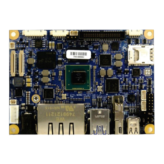
Page 21: Mainboard Placement And Rear I/O Locations
– Rev. 0.1 Preliminary 5.2. Mainboard Placement and Rear I/O locations Figure 3: Front Side and Interfaces www.kontron.com // 21... - Page 22 – Rev. 0.1 Preliminary 12 Internal DC Power connector (J16) SPI header 13 SPDIF header (J10) Internal Audio Header (J26) 14 2x Camera connector (J5, J6) LVDS Voltage Jumper (J18) 15 Pigtail battery header (J22) Fan connector (J8) 16 DC Power Jack...
-
Page 23: Rear Side
– Rev. 0.1 Preliminary 5.2.1. Rear Side Figure 4: Rear Side 21 M.2 connector www.kontron.com // 23... -
Page 24: Figure 5: System Parts With Integrated Premounted Cooler
– Rev. 0.1 Preliminary Figure 5: System parts with integrated premounted cooler www.kontron.com // 24... -
Page 25: 6/ Pin Definitions
– Rev. 0.1 Preliminary 6/ Pin Definitions The following sections provide pin definitions and detailed description of all on-board connectors. The connector definitions follow the following notation: Table 5: Connector Definitions Column Name Description Shows the pin-numbers in the connector. The graphical layout of the connector definition tables is made similar to the physical connectors. -
Page 26: Processor Support
8M QuadLite (1.5 GHz/Consumer) i.MX 8M Dual (1.3 GHz/Industry) i.MX 8M Dual (1.5 GHz/Consumer) Kontron has defined the board versions as listed in the following table, so far all based on Embedded CPUs. Table 6: Processor Support Name Speed (GHz) Cache Cores i.MX 8M QuadLite... -
Page 27: System Memory Support
Figure 6: Block Diagram i.MX8M processor (Source: NXP) 6.2. System Memory Support The pITX-iMX8M board supports a 32-bit DRAM interface LPDDR4 memory interface. The integrated memory controller can support memory speeds up to 3200 MT/s. Maximum memory supported is 4GB. -
Page 28: Microsd And Microsim (J12)
– Rev. 0.1 Preliminary 6.3. MicroSD and MicroSIM (J12) The pITX-iMX8M board supports micro SD cards via micro SD/micro SIM combo connector. Figure 7: Combo Connector for MicroSD and MicroSIM Table 7: Pin Assignment MicroSIM Type V_VCC CLK_S3 RSVD_S4... -
Page 29: Ethernet Connectors (I/O Area)
– Rev. 0.1 Preliminary 6.4. Ethernet Connectors (I/O area) The pITX-iMX8M supports two channels of 10/100/1000 Mbit/s Ethernet (LAN1 to LAN2). In order to achieve the specified performance of the Ethernet port, Category 5 twisted pair cables must be used with 10/100 MByte/s and Category 5E, 6 or 6E with 1 Gbit/s LAN networks. -
Page 30: Usb Connectors (I/O Area)
– Rev. 0.1 Preliminary 6.5. USB Connectors (I/O area) pITX-iMX8M board supports a dual-stacked USB3.0 interface with 5 Gbps speed. The following connections are available for the USB 3.0: 1x Dual-stacked USB3.0 Type A at rear I/O ... -
Page 31: Figure 10: Usb 2.0 High Speed Cable
– Rev. 0.1 Preliminary Figure 10: USB 2.0 High Speed Cable Polyvinyl Chloride (PVC) Jacket On-Twisted Power Pair: Red: V Black: Power Ground Twisted Signaling Pair: White: D- Green: D+ Inner Shield Aluminum Metallized Polyester Outer Shield ≥ 65% Interwoven... -
Page 32: Fan Connector (Internal, J8)
– Rev. 0.1 Preliminary 6.6. Fan Connector (internal, J8) The Fan can be used to actively cool the heatsink mounted on the board. The fan rotation speed can be monitored and the fan speed controlled by the temperature of the PCB (near SoC). -
Page 33: Dc Power Jack Connector (5 Vin Ext., J15)
– Rev. 0.1 Preliminary 6.7. DC Power Jack Connector (5 Vin Ext., J15) Figure 13: Power Jack Connector Either the DC Power Jack Connector (5 Vin Ext.) or the “5 Vin Int.” connector must be used to supply the board with +5V +/-5 %. -
Page 34: Pigtail Battery Header (J22)
– Rev. 0.1 Preliminary 6.8. Pigtail Battery Header (J22) Figure 14: Pigtail Battery Header Table 15: Pin Assignment Signal V_BAT 6.9. Internal Power Connector (Vin Int., J16) Figure 15: Internal Power Connector Table 16: Internal Power Connector Header Signal... -
Page 35: Usb Internal (J2, J3)
– Rev. 0.1 Preliminary 6.10. USB internal (J2, J3) Figure 16: USB Internal Connector Table 17: USB Internal Connection Description Description USB_Pn+ USB_Pn- 5 V/SB 5 V 6.11. GPIO Connector (internal, J17) Figure 17: GPIO Connector Table 18: GPIO Connector... -
Page 36: Jumper Internal Boot (J21)
– Rev. 0.1 Preliminary 6.12. Jumper Internal Boot (J21) Figure 18: Jumper Internal Boot Table 19: Jumper Internal Boot Description SCU_BOOT_MODE0 SCU_BOOT_MODE1 Function: Pin 1-2: Internal Boot [Default] Pin 2-3: Boot From Fuse 6.13. Jumper Autostart/Always ON (J20) Figure 19: Always ON... -
Page 37: Jumper Lvds Panel Voltage (J18)
– Rev. 0.1 Preliminary 6.14. Jumper LVDS Panel Voltage (J18) Figure 20: LVDS Panel Voltage Table 21: LVDS Panel Voltage Description V_5V0_S0 V_5V0_3V3_JP V_3V3_S0 Function: Pin1-2: 5V LVDS Panel Voltage Pin2-3: 3.3V LVDS Panel Voltage (Default 6.15. LVDS (internal, J11) -
Page 38: Hdmi Connector (J7)
– Rev. 0.1 Preliminary Description Description LVDS_A_DATA0- LVDS_A_DATA_A0+ LVDS_A_DATA1- LVDS_A_DATA_A1+ LVDS_A_DATA2- LVDS_A_DATA_A2+ LVDS_A_CLK- LVDS_A_CLK+ LVDS_A_DATA3- LVDS_A_DATA3+ LVDS_B_DATA0- LVDS_B_DATA_A0+ LVDS_B_DATA1- LVDS_B_DATA1+ LVDS_B_DATA2- LVDS_B_DATA2+ LVDS_B_CLK- LVDS_B_CLK+ LVDS_B_DATA3- LVDS_B_DATA3+ 6.16. HDMI connector (J7) Figure 22: 19-pin HDMI connector Signal TMDS Data2+ TMDS Data2 Shield TMDS Data2−... -
Page 39: Mini Display Port (J14)
– Rev. 0.1 Preliminary Signal +5V Power Hot Plug Detect 6.17. Mini Display Port (J14) The two external Display Port 1.2 at rear I/O space are supporting Active/Passive HDMI 1.4a and DVI adapters. Figure 23: Mini Display Port Table 23: Mini Display Port... -
Page 40: Spdif Internal Audio Header (J9)
– Rev. 0.1 Preliminary 6.18. SPDIF Internal Audio Header (J9) Figure 24: SPDIF Internal Header Table 24: Pin Assignment J9 Signal LINE_OUT_R_C LINE_OUT_L_C LINE_IN_R_C MIC_IN_C LINE_IN_L_C 6.19. M.2 Connector (mPCIe/mSATA) (J1) The Slot connector has two functions: mSATA or miniPCIe. The Slot connector detects the mounted card technology with autosensing. - Page 41 – Rev. 0.1 Preliminary Signal Type +1.5V CLKREQ# UIM_PWR UIM_DATA PCIE_mini CLK# UIM_CLK PCIE_mini CLK UIM_RESET UIM_VPP UIM_IC_DM UIM_IC_DP W_Disable# RST# PCIE_RX-/SATA_RX- +3V3 PCIE_RX+/SATA_RX+ +1.5 V SMB_CLK PCIE_TX-/SATA_TX- SMB_DATA PCIE_TX+/SATA_TX+ USBhub_D1_N USBhub_D1_P +3V3 +3V3 SATA_DET5# www.kontron.com // 41...
-
Page 42: Serial Com (J19)
– Rev. 0.1 Preliminary Signal Type +1.5 V +3V3 6.20. Serial COM (J19) Figure 26: Serial COM Table 26: Pin Assignment Signal RS232_TXD RS232_RXD RS232_RTS# RS232_CTS# 6.21. Camera connector (J5, J6) Figure 27: 24-pin Camera CSI Connector Table 27: Pin Assignment (J5) -
Page 43: Table 28: Pin Assignment (J6)
– Rev. 0.1 Preliminary Signal CSI0_CLK- CSI0_CLK+ CSI0_RX1- CAM_XCLK_1V8_CAM1 CSI0_RX1+ V_1V8_S0 V_1V5_CAM CSIO_P1_PWDN_1V8 CAM_RST_1V8# I2C1_SCL_1V8_CAM1 V_2V8_CAM I2C1_SDA_1V8_CAM1 Table 28: Pin Assignment (J6) Signal 2V8_CAM CSI2_RX0- CSI2_RX0+ CSI2_CLK- CSI2_CLK+ CSI2_RX1- CAM_XCLK_1V8_CAM2 CSI2_RX1+ V_1V8_S0 V_1V5_CAM CSI_P2_PWDN_1V8 www.kontron.com // 43... - Page 44 – Rev. 0.1 Preliminary Signal CAM_RST_1V8# I2C3_SCL_1V8_CAM2 V_2V8_CAM2 I2C3_SDA_1V8_CAM2 www.kontron.com // 44...
-
Page 45: 7/ Uefi Bios
Supervisor Password (see Security menu), press <RETURN>, and proceed with step 5. A Setup menu will appear. The pITX-iMX8M uEFI BIOS Setup program uses a hot key-based navigation system. A hot key legend bar is located on the bottom of the Setup screens. -
Page 46: Setup Menus
– Rev. 0.1 Preliminary 7.2. Setup Menus The Setup utility features a selection bar at the top of the screen that lists the available menus: Main Advanced Chipset Security Boot Save & Exit The currently active menu and the currently active uEFI BIOS Setup item are highlighted in white. Use the left and right arrow keys to select the Setup menus. -
Page 47: Table 30: Main Setup Menu Sub-Screens
– Rev. 0.1 Preliminary Table 30: Main Setup Menu Sub-screens Sub-Screen Function Second level Sub-Screen / Description Read only field BIOS Displays BIOS Information Information Board Vendor, BIOS Version, Build Date and Time, Access Level Read only field Board... -
Page 48: Advanced Setup Menu
– Rev. 0.1 Preliminary 7.2.2. Advanced Setup Menu The Advanced Setup menu provides sub-screens and second level sub-screens with functions, for advanced configuration and Kontron specific configurations. Setting items, on this screen, to incorrect values may cause system malfunctions. -
Page 49: Table 31: Advanced Setup Menu Sub-Screens And Functions
– Rev. 0.1 Preliminary Table 31: Advanced Setup menu Sub-screens and Functions Sub-Screen Function Second level Sub-Screen / Description Intel® PRO/1000 7.0.06 PCI-E Driver Health When set to Enable: Active PCR banks Available PCR banks SHA-1 PCR Bank [Enabled]... - Page 50 – Rev. 0.1 Preliminary Sub-Screen Function Second level Sub-Screen / Description Parity [None] Stop Bits [1] Turbo Mode [Enabled] Intel Virtualization Technology [Enabled] Configurati VT-d [Disabled] Monitor Mwait [Disabled] AMI Graphic Intel ® Graphics Controller Output Intel ® GOP Driver...
- Page 51 – Rev. 0.1 Preliminary Sub-Screen Function Second level Sub-Screen / Description When set to Enabled: Panel Type [Standard] Resolution [1024 x 768] Panel Color Depth [24-Bit VESA] Panel Voltage [3.3V] LVDS Channel [Dual] LVDS Flat Panel Display Configurati Support [Disabled]...
- Page 52 – Rev. 0.1 Preliminary Sub-Screen Function Second level Sub-Screen / Description DDR SSC Bending Selection Table [0% (No Clock Bending)] When set to Enable: HighSpeed SerialIO SSC [Enable] HighSpeed SerialIO SSC Selection Table [-0.5%] Kernel Debugger Configuration Kernel Debugger Enable [Disabled]...
-
Page 53: Chipset Setup Menu
– Rev. 0.1 Preliminary Sub-Screen Function Second level Sub-Screen / Description Punit Message Level [LEVEL LOW] PMC Message Level [LEVEL LOW] Native PCIE Enable [Enable] RC ACPI Settings Native ASPM [Enable] RTD3 RTD3 Support [Disable] Settings 7.2.3. Chipset Setup Menu The Chipset Setup menu provides sub-screens, second level and third level sub-screens with functions, for Intel Chipset configurations. - Page 54 – Rev. 0.1 Preliminary Sub-Screen Function Second level Sub-Screen / Description OS Selection [Windows 10 (Ver>=167)] PCI Clock Run [Enable] Real Time Option [RT Disable] GOP Configuration Uncore GOP Driver [Enable] Configuration Intel Graphics Pei Display PEIM [Disable] GOP Brightness Level [140]...
- Page 55 – Rev. 0.1 Preliminary Sub-Screen Function Second level Sub-Screen / Description PCH PCIE LTR [Enable] Snoop Latency Override [Auto] Non Snoop Latency Override [Auto] PCIE LTR Lock [Disable] PCIE Selectable De-emphasis [Enable] SATA Drives Chipset-SATA Controller Configuration SATA Port 0...
-
Page 56: Security Setup Menu
Linux boot loader signed with Microsoft’s platform key. Select “Customized” mode only if you have a custom OS with OS boot loader signed with your own platform key. Kontron provide services for Customized Secure Boot, visit Kontron SEC-Line home www.kontron.com... -
Page 57: Remember The Password
– Rev. 0.1 Preliminary Function Description page https://www.kontron.com/products/solutions/security/sec- line.html for more information. Key Management Enables expert users to modify Secure Boot Policy Variables without full authentication. If only the administrator’s password is set, then only access to the setup is limited and is requested when entering the setup. -
Page 58: Boot Setup Menu
– Rev. 0.1 Preliminary 7.2.5. Boot Setup Menu The Boot Setup menu lists dynamically generated boot device priority order. Figure 32: Boot Setup Menu Initial Screen The following table shows Boot sub-screens and functions, and describes the content. Default settings are in bold. - Page 59 – Rev. 0.1 Preliminary Function Description PS2 Support Network Stack Driver Support Redirection Support New Boot Option Policy Controls the placement of newly detected UEFI boot options Hard Drive BBS Priotities Sets the placement of legacy boot options www.kontron.com...
-
Page 60: Exit Setup Menu
– Rev. 0.1 Preliminary 7.2.6. Exit Setup Menu The Save and Exit Setup menu provides functions for handling changes made to the uEFI BIOS settings and exiting the Setup program. If system cannot boot or work properly due to incorrect setting, shorting Pin-1 and Pin-2 on J15 jumper will load the default setting of BIOS upon power cycle. -
Page 61: The Uefi Shell
7.3. The uEFI Shell The Kontron uEFI BIOS features a built-in and enhanced version of the uEFI Shell. For a detailed description of the available standard shell scripting, refer to the EFI Shell User Guide. For a detailed description of the available standard shell commands, refer to the EFI Shell Command Manual. -
Page 62: Uefi Shell Scripting
Initially searches for Kontron flash-stored startup script. If there is no Kontron flash-stored startup script present then the uEFI-specified startup.nsh script is used. This script must be located on the root of any of the attached FAT formatted disk drive. - Page 63 – Rev. 0.1 Preliminary OR type fpt –y –f pITX_IMX8M_BIOS_Ver_<xxx>……bin Wait until flashing is successful and then power cycle the board. Do not switch off the power during the flash process! www.kontron.com // 63...
-
Page 64: List Of Acronyms
– Rev. 0.1 Preliminary List of Acronyms Display Port Digital Video Interface Embedded DisplayPort Electromagnetic Interference Electrostatic Discharge FCBGA Flip Chip Ball Grid Array Firmware Hub HDMI High Definition Multimedia Interface Low Pin Count LVDS Low Voltage Differential Signaling... -
Page 65: About Kontron
About Kontron Kontron, a global leader in embedded computing technology and trusted advisor in Internet of Things (IoT), works closely with its customers, allowing them to focus on their core competencies by offering a complete and integrated portfolio of hardware, software and services designed to help them make the most of their applications.
Need help?
Do you have a question about the pITX-iMX8M and is the answer not in the manual?
Questions and answers