Table of Contents
Advertisement
Quick Links
Advertisement
Table of Contents

Related Manuals for Kontron PITX-IMX8M


Summary of Contents for Kontron PITX-IMX8M
- Page 1 USER GUIDE pITX-iMX8M Doc. Rev. 0.7 Preliminary Doc-ID: 1064-7940...
- Page 2 – Rev. 0.7 Preliminary This page has been intentionally left blank...
- Page 3 Kontron with respect to technical processes described in the manual or any product characteristics set out in the manual. Kontron assumes no responsibility or liability for the use of the described product(s), conveys no license or title under any patent, copyright or mask work rights to these products and makes no representations or warranties that these products are free from patent, copyright or mask work right infringement unless otherwise specified.
- Page 4 SEVERE PHYSICAL OR ENVIRONMENTAL DAMAGE (COLLECTIVELY, "HIGH RISK APPLICATIONS"). You understand and agree that your use of Kontron devices as a component in High Risk Applications is entirely at your risk. To minimize the risks associated with your products and applications, you should provide adequate design and operating safeguards.
- Page 5 If you have any difficulties using this user guide, discover an error, or just want to provide some feedback, contact Kontron support. Detail any errors you find. We will correct the errors or problems as soon as possible and post the revised user guide on our website.
-
Page 6: Symbols
– Rev. 0.7 Preliminary Symbols The following symbols may be used in this manual DANGER indicates a hazardous situation which, if not avoided, will result in death or serious injury. WARNING indicates a hazardous situation which, if not avoided, could result in death or serious injury. -
Page 7: Table Of Contents
– Rev. 0.7 Preliminary Table of Contents Symbols ..........................................6 Table of Contents ....................................... 7 List of Tables ........................................8 List of Figures ........................................9 Introduction ......................................11 Description ......................................12 2.1. Configurations ......................................13 2.2. Scope of Delivery ...................................... 14 Installation procedure .................................. -
Page 8: List Of Tables
About Kontron ........................................64 List of Tables Table 1: Component Main Data ..................................13 Table 2: Scope of Delivery pITX-iMX8M ..............................14 Table 3: Scope of pITX-iMX8M Kit ................................14 Table 4: Component Main Data ................................... 18 Table 5: Environmental Conditions................................20 Table 6: Connector Definitions .................................. -
Page 9: List Of Figures
– Rev. 0.7 Preliminary Table 16: Power Jack Connector ................................. 36 Table 17: Pin Assignment ....................................37 Table 18: Internal Power Connector ................................37 Table 19: USB Internal Connection ................................38 Table 20: GPIO Connector ..................................... 38 Table 21: LVDS Panel Voltage ..................................39 Table 22: Boot Select Switch (SW1) ................................ - Page 10 – Rev. 0.7 Preliminary Figure 29: Sensor Location (red circle) ..............................51 Figure 30: U-Boot Start Screen ................................... 53 www.kontron.com // 10...
-
Page 11: 1/ Introduction
This manual describes the pico-ITX board with five processors from NXP: i.MX8M QuadLite with 1.5 GHz, i.MX8M Dual with 1.3 GHz and 1.5 GHz, i.MX8M Quad with 1.3 GHz and 1.5 GHz. This board will also be denoted pITX-iMX8M within this Users Guide. -
Page 12: 2/ Description
+12V DC Input via locking barrel-type connector or Internal Power Header pITX form factor and cooling solution Built with these functions, pITX-iMX8M Mother Board is ideal for ATM, Automation, Kiosk applications, medical equipment, industrial automation, financial automation, process control, semiconductor equipment and network security markets. -
Page 13: Configurations
– Rev. 0.7 Preliminary 2.1. Configurations Kontron offers the pITX-iMX8M in different configurations. The products can be ordered in four different flavors. Table 1: Component Main Data Product Number Article Dedcription 44011-0408-13-4 pITX-iMX8M Quad Core pITX-imx8m with NXP Arm® Cortex®-A53 Quad Industrial Core™... -
Page 14: Scope Of Delivery
– Rev. 0.7 Preliminary 2.2. Scope of Delivery Table 2: Scope of Delivery pITX-iMX8M Part Description Module pITX-iMX8M Miscellaneous Quick Installation Guide Table 3: Scope of pITX-iMX8M Kit Part Part No. Description Module pITX-iMX8M Power Supply 1067-1755 12 V Power Supply: SCM PSU AC/DC 60W 12V KYCON (0-40°C), AC Power... -
Page 15: 3/ Installation Procedure
• Handle the board only by the edges To get the board running follow these steps. If the board shipped from Kontron has already components like RAM and CPU cooler mounted, then relevant steps below can be skipped. Turn off the PSU (Power Supply Unit) Turn off PSU (Power Supply Unit) completely (no mains power connected to the PSU) or leave the Power Connectors unconnected while configuring the board. -
Page 16: Requirements Iec60950-1
– Rev. 0.7 Preliminary When mounting the board to chassis etc. please notice that the board contains components on both sides of the PCB which can easily be damaged if board is handled without reasonable care. A damaged component can result in malfunction or no function at all. -
Page 17: Lithium Battery Precautions
– Rev. 0.7 Preliminary 3.3. Lithium battery precautions Danger of explosion if the lithium battery is incorrectly replaced. • Replace only with the same or equivalent type recommended by the manufacturer • Dispose of used batteries according to the manufacturer’s instructions VORSICHT! Explosionsgefahr bei unsachgemäßem Austausch der Batterie. -
Page 18: 4/ System Specifications
– Rev. 0.7 Preliminary 4/ System specifications 4.1. Component Main Data The table below summarizes the features of the pITX-iMX8M embedded motherboard. Table 4: Component Main Data Motherboard pITX-iMX8M Form factor Pico-ITX (100 mm by 72 mm by 1.6 mm/Length x Width x Thickness) - Page 19 – Rev. 0.7 Preliminary Dual Channel LVDS Dual channel LVDS, 18 bit support, 24 bit (VESA mapping) support, 24 bit (Open LDI mapping) support, Resolution: up to 60 fps at 1920 x 1080 pixel HDMI 1x HDMI2.0a at rear I/O...
-
Page 20: Environmental Conditions
– Rev. 0.7 Preliminary 4.2. Environmental Conditions Table 5: Environmental Conditions Storage IEC 60068-2-1 60068-2-2 Temperature -40°C to +85°C Operating IEC 60068-2-1 60068-2-2 Temperature -40°C to +85°C for Extended Consumer Variants 0°C to +60°C for Commercial Temperature Variants Humidity IEC 60068-2-78 50% to 95% Relative Humidity at 25°C to 30°C, non- condensing... -
Page 21: Block Diagram
– Rev. 0.7 Preliminary 4.3. Block Diagram Figure 2: Block Diagram www.kontron.com // 21... -
Page 22: 5/ Jumpers And Connectors
– Rev. 0.7 Preliminary 5/ Jumpers and Connectors 5.1. Hardware Configuration Setting This chapter gives the definitions and shows the positions of jumpers, headers and connectors. All of the configuration jumpers on the board are in the proper position. The default settings shipped from factory are marked with an asterisk (*). -
Page 23: Mainboard Placement And I/O Locations
– Rev. 0.7 Preliminary 5.2. Mainboard Placement and I/O Locations Figure 3: Front Side 10 USB OTG (J28) SPI/I2C header (J26) 11 GPIO connector (J17) Internal Audio Codec (J9) 12 Internal DC Power connector (J16) LVDS Voltage Jumper (J18) -
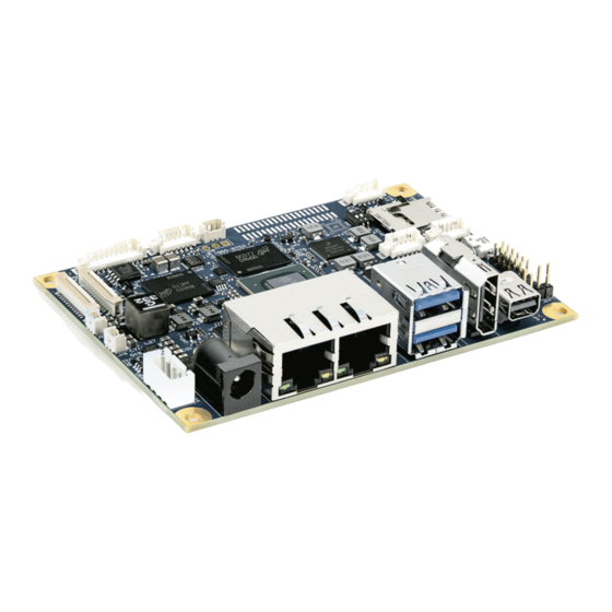
Page 24: Figure 4: Interfaces
– Rev. 0.7 Preliminary Figure 4: Interfaces 17 DC Power Jack 18 2x Ethernet 19 2x USB 3.0 20 HDMI 21 Mini DP www.kontron.com // 24... -
Page 25: Figure 5: Front View Jumpers/Switches
– Rev. 0.7 Preliminary Figure 5: Front View Jumpers/Switches 22 Switch MicroSD (SW2) 23 Switch Boot Select (SW1) 24 External ON/OFF (J24) 25 External Reset (J23) www.kontron.com // 25... -
Page 26: Rear Side
– Rev. 0.7 Preliminary 5.2.1. Rear Side Figure 6: Rear Side 26 M.2 connector 5.3. Passive Cooler (1064-7069) Figure 7: Passive Cooler www.kontron.com // 26... -
Page 27: 6/ Pin Definitions
– Rev. 0.7 Preliminary 6/ Pin Definitions The following sections provide pin definitions and detailed description of all on-board connectors. The connector definitions follow the following notation: Table 6: Connector Definitions Column Name Description Shows the pin-numbers in the connector. The graphical layout of the connector definition tables is made similar to the physical connectors. -
Page 28: Processor Support
8M Quad (1.3/1.5 GHz, Industry/Consumer) i.MX 8M QuadLite (1.5 GHz/Consumer) i.MX 8M Dual (1.3/1.5 GHz, Industry/Consumer) Kontron has defined the board versions as listed in the following table, so far all based on Embedded CPUs. Table 7: Processor Support Name Speed Cache... -
Page 29: System Memory Support
Figure 8: Block Diagram i.MX8M processor (Source: NXP) 6.2. System Memory Support The pITX-iMX8M board supports a 32-bit DRAM interface LPDDR4 memory interface. The integrated memory controller can support memory speeds up to 3200 MT/s. Maximum memory supported is 4 GB. -
Page 30: Microsd And Microsim (J12)
– Rev. 0.7 Preliminary 6.3. MicroSD and MicroSIM (J12) The pITX-iMX8M board supports micro SD cards via micro SD/micro SIM combo connector. The micro SD card interface supports the following transfer modes: SD 1-bit SD 4-bit ... -
Page 31: Ethernet Connectors (I/O Area, J4)
Ground 6.4. Ethernet Connectors (I/O area, J4) The pITX-iMX8M supports two channels of 10/100/1000 Mbit/s Ethernet (LAN1 to LAN2). In order to achieve the specified performance of the Ethernet port, Category 5 twisted pair cables must be used with 10/100 MByte/s and Category 5E, 6 or 6E with 1 Gbit/s LAN networks. -
Page 32: Gbe0
GBE1 port uses an Intel I210/I211 10/100/1000Base-T Ethernet controller connected to iMX8 M PCIe 2 interface. The I210/I211 SMB IF connects to iMX8 M I2C 2 interface. The I2C 7-bit address is 0x92. The pITX-IMX8M does not support I210 external NVM. The Intel I210/I211 LED outputs drive the RJ45 integrated LEDs. -
Page 33: Table 12: Pin Assignment Dual Usb
– Rev. 0.7 Preliminary Figure 11: USB 2.0/3.0 socket USB 2.0 USB 3.0 Table 12: Pin Assignment Dual USB Connector Pin Direction Description VBUS_BOT POWER USB 5V Power Distribution to downstream device. USB_BOT_D- BIDIR USB3 HUB P2 differential USB 2.0 data pairs. -
Page 34: Figure 12: Usb 2.0 High Speed Cable
– Rev. 0.7 Preliminary Figure 12: USB 2.0 High Speed Cable Polyvinyl Chloride (PVC) Jacket On-Twisted Power Pair: Red: V Black: Power Ground Twisted Signaling Pair: White: D- Green: D+ Inner Shield Aluminum Metallized Polyester Outer Shield ≥ 65% Interwoven... -
Page 35: Fan Connector (Internal, J8)
– Rev. 0.7 Preliminary 6.6. Fan Connector (internal, J8) The fan can be used to actively cool the heatsink mounted on the board. The fan rotation speed can be monitored and the fan speed controlled by the temperature of the PCB (near SoC). -
Page 36: Dc Power Jack Connector (12 Vin Ext., J15)
– Rev. 0.7 Preliminary 6.7. DC Power Jack Connector (12 Vin Ext., J15) The pITX-iMX8M operates with a 12 V DC +/- 10% power supply. Figure 15: Power Jack Connector Either the DC Power Jack Connector (12 Vin Ext.) or the “12 Vin Int.” connector must be used to supply the board with +12 V +/-10 %. -
Page 37: Pigtail Battery Header (J22)
Figure 16: Pigtail Battery Header Table 17: Pin Assignment Signal V_BAT 6.9. Internal Power Connector (Vin Int., J16) The pITX-iMX8M operates with a 12 V DC +/- 10% power supply. Figure 17: Internal Power Connector Table 18: Internal Power Connector Header Signal... -
Page 38: Usb Internal (J2)
– Rev. 0.7 Preliminary 6.10. USB internal (J2) Figure 18: USB Internal Connector Table 19: USB Internal Connection Function Direction Description Ground USB3_P4_D+ In/Out USB3_P4_D- In/Out V_5V0_USB Power VBUS +5.0V power distribution 500mA max 6.11. GPIO Connector (internal, J17) -
Page 39: Jumper Lvds Panel Voltage (J18)
– Rev. 0.7 Preliminary Function Direction Description Ground V_BAT_GPIO Power Connects to RTC battery power rail. 6.12. Jumper LVDS Panel Voltage (J18) Figure 20: LVDS Panel Voltage Table 21: LVDS Panel Voltage Function Direction V_5V_S0 Power V_5V0_3V3_JP Power V_3V3_S0... -
Page 40: Pcie Spread Spectrum Clocking -0.5% (Sw2: 2-3)
– Rev. 0.7 Preliminary SDIO_WP Description MicroSD card write protection is disabled. MicroSD card write protection is active 6.13.3. PCIE Spread Spectrum Clocking -0.5% (SW2: 2-3) Table 24: PCIE Spread Spectrum Clocking -0.5% Switch SW2: 2-3 CLK_GEN_ SS_EN Description PCIe clock generator spread spectrum clock is disabled. -
Page 41: Buttons
– Rev. 0.7 Preliminary 6.14. Buttons 6.14.1. External ON-OFF Button (J24) Table 25: External ON-OFF Button Function Direction ON-OFF Ground 6.14.2. External Reset (J23) Table 26: External Reset Button Function Direction RESET# Ground www.kontron.com // 41... -
Page 42: Lvds (Industrial Variant, Internal, J11)
– Rev. 0.7 Preliminary 6.15. LVDS (Industrial Variant, internal, J11) Figure 21: LVDS Connector (optional) Table 27: LVDS Pin Assignment Function Direction Description V_12V_LVDS_BS Power +12V LVDS Backlight Circuit Supply V_12V_LVDS_BS Power +12V LVDS Backlight Circuit Supply V_12V_LVDS_BS Power... -
Page 43: Hdmi Connector (J7)
– Rev. 0.7 Preliminary Function Direction Description LVDS1_1+ LVDS channel 1, lane 1, positive LVDS1_2- LVDS channel 1, lane 2, negative LVDS1_2+ LVDS channel 1, lane 2, positive LVDS1_CK- LVDS channel 1, clock, negative LVDS1_CK+ LVDS channel 1, clock, positive... -
Page 44: Mini Display Port (J14)
– Rev. 0.7 Preliminary 6.17. Mini Display Port (J14) The two external Display Port 1.2 at rear I/O space are supporting Active/Passive HDMI 1.4a and DVI adapters. Figure 23: Mini Display Port Table 29: Mini Display Port Function Direction... -
Page 45: Spdif Internal Audio Header (J10)
– Rev. 0.7 Preliminary 6.18. SPDIF Internal Audio Header (J10) Figure 24: SPDIF Internal Header Table 30: Pin Assignment J9 Function Direction SPDIF Ground SPDIF is a Sony/Philips Digital Interface 3.3 V VIO. Other levels below +3.3V VIO are possible via resistor divider (assembly option). -
Page 46: Connector (B-Key) (J1)
– Rev. 0.7 Preliminary 6.20. M.2 Connector (B-Key) (J1) Figure 25: M.2 Connector (B-Key) Table 32: Pin Assignment Signal/Function M.2 Signal M.2 Signal Signal/Function M2_CONFIG_3, 3.3V CONFIG_3 Pull-up to 3.3V S0 V_3V3_M2 3.3V (V_3V3_S0) M2_FULL_CARD_ FULL_CARD_POWER POWER_OFF# pulled _OFF# (O) (0/1.8V up to V_3V3_M2 or 3.3V) - Page 47 – Rev. 0.7 Preliminary Signal/Function M.2 Signal M.2 Signal Signal/Function DEVSLP (O) PETp1/USB3.0-Tx+/ USB3_SSTX_M2+ SSIC-TxP I2C2_SCL_3V3 GPIO_0 (I/O)(0/1.8V) I2C2_SDA_3V3 GPIO_1 (I/O)(0/1.8V) PERn0/SATA-B+ PCIE_M2_RX_+ GPIO_2 (I/O)(0/1.8V) PERp0/SATA-B- PCIE_M2_RX_- GPIO_3 (I/O)(0/1.8V) GPIO_4 (I/O)(0/1.8V) PETn0/SATA-A- PCIE_M2_TX_- M2_PERST# IMX8M PERST# (O) (0/3.3V) PETp0/SATA-A+...
-
Page 48: Serial Com/Rs232 P3 (J19)
– Rev. 0.7 Preliminary 6.21. Serial COM/RS232 P3 (J19) Figure 26: Serial COM/RS232 Table 33: Pin Assignment Signal Direction RS232_P3_TXD RS232_P3_RXD RS232_P3_RTS# RS232_P3_CTS# Ground 6.22. Serial COM/UART P1 (J25) Figure 27: Serial COM UART P1 Table 34: Pin Assignment... -
Page 49: Camera Connector (J5, J6)
– Rev. 0.7 Preliminary 6.23. Camera connector (J5, J6) Figure 28: 24-pin Camera CSI Connector Table 35: Pin Assignment (J5) Signal Direction V_2V8_CAM1_S0 Power CSI1_RX0- CSI1_RX0+ CSI1_CK- CSI1_CK+ CSI1_RX1- CAM_XCLK_1V8_CAM1 CSI1_RX1+ V_1V8_S0_CSI1 Power V_1V5_CAM_CSI1 Power CSI_P1_PWDN_1V8 CSI_P1_RST_1V8# I2C1_SCL_1V8 V_2V8_CAM1_S0... - Page 50 – Rev. 0.7 Preliminary Signal Direction CSI2_CK- CSI2_CK+ CSI2_RX1- CAM_XCLK_1V8_CAM1 CSI2_RX1+ V_1V8_S0_CSI1 Power V_1V5_CAM_CSI1 Power CSI_P2_PWDN_1V8 CSI_P2_RST_1V8# I2C3_SCL_1V8 V_2V8_CAM2_S0 Power I2C3_SDA_1V8 In/Out Ground www.kontron.com // 50...
-
Page 51: Thermal Sensor (U24)
– Rev. 0.7 Preliminary 6.24. Thermal Sensor (U24) The pITX-IMX8M monitors the PCB ambient temperature between iMX8 M, eMMC and LPDDR4 device with an LM75B temperature sensor. The iMX8 M I2C 1 interface connects to LM75B. The I2C 7-bit address is set to 0x4B. -
Page 52: 7/ Bootloader Operation
Additionally the software can be downloaded from Kontron GitHub repository for PITX- iMX8M: https://kdp.kontron.local/git/pitx-imx8m-uboot/uboot_imx8m.git 7.2. Bootloader Quickstart The PITX-iMX8M board comes with U-Boot preinstalled on the QSPI flash device. Follow the steps below to gain access to the bootloader command line (CLI) on your host PC. ... -
Page 53: Bootloader Commands
Typing “help <command>” will show specific command help. Further help can be found under https://www.denx.de/wiki/view/DULG/UBoot On the PITX-iMX8M bootloader, the powerful hush shell is enabled, which is similar to Bourne shell and provides features similar to a linux shell: ... -
Page 54: Kontron Bootloader Command Extensions
7.4. Kontron Bootloader Command Extensions Kontron’s implementation of U-Boot includes certain enhancements to provide board specific functions. They are not part of standard U-Boot as maintained by DENX. The following table provides a complete listing of all Kontron command extensions on the PITX-iMX8M. -
Page 55: Watchdog - Cpu Watchdog Control
The following sequence shows how to load both image file and image checksum file into PITX-iMX8M memory and compare them. In case of success, the "md5sum -a" command will have no output messages as this extensions is meant to be used in automatic update scripts to check the binary images against their MD5 checksum. -
Page 56: Bootloader Environment Update
On the PITX-iMX8M it is possible to update the U-Boot environment separately. This enables the user to either update from a previous version of the official Kontron U-Boot environment (default U-Boot settings), or restore the default in case of problems. -
Page 57: Kontron Bootloader Environment Extensions
– Rev. 0.7 Preliminary 7.7. Kontron Bootloader Environment Extensions To support PITX-iMX8M board properly, Kontron adds some environment variables to the standard set of variables provided by mainline U-Boot. These variables are shown below. Table 39: Bootloader Environment Extensions... -
Page 58: Usb Storage Device
7.9. Bootloader File System Support U-Boot for the PITX-iMX8M provides support for FAT and EXT4 file systems. EXT4 support also includes EXT2 and EXT3 formatted file systems. There are file system specific commands available to list file system contents (ext2ls, fatls) and load a given file into board memory (ext2load, fatload). -
Page 59: Bootloader Boot Source Support
KEU EEPROM Specification Rev. 1.4. The running-time data block structure implements a 64bit boot counter. U-Boot on the pITX-iMX8M module will read the current boot counter value and increment it on every boot cycle. Current boot counter is shown as part of the information shown by the "kboardinfo" command (see description of kboardinfo). - Page 60 – Rev. 0.7 Preliminary Given these prerequisites are met, update can be done from bootloader CLI using the predefined "update" script: => run update Or, in case of network update => run updNet It is recommended to use only the update script for bootloader update. This ensures that all necessary installation images are checksum controlled and copied to the appropriate location in QSPI flash.
-
Page 61: 8/ Technical Support
Visit the RMA Information website: http://www.kontron.com/support-and-services/support/rma-information Download the RMA Request sheet for Kontron Europe GmbH and fill out the form. Take care to include a short detailed description of the observed problem or failure and to include the product identification Information (Name of product, Product number and Serial number). - Page 62 – Rev. 0.7 Preliminary The goods for repair must be packed properly for shipping, considering shock and ESD protection. Goods returned to Kontron Europe GmbH in non-proper packaging will be considered as customer caused faults and cannot be accepted as warranty repairs.
-
Page 63: List Of Acronyms
– Rev. 0.7 Preliminary List of Acronyms Display Port Digital Video Interface Embedded DisplayPort Electromagnetic Interference Electrostatic Discharge FCBGA Flip Chip Ball Grid Array Firmware Hub HDMI High Definition Multimedia Interface Low Pin Count LVDS Low Voltage Differential Signaling... -
Page 64: About Kontron
About Kontron Kontron is a global leader in Embedded Computing Technology (ECT). As a part of technology group S&T, Kontron offers a combined portfolio of secure hardware, middleware and services for Internet of Things (IoT) and Industry 4.0 applications. With its standard products and tailor-made solutions based on highly reliable state-of-the-art embedded technologies, Kontron provides secure and innovative applications for a variety of industries.
Need help?
Do you have a question about the PITX-IMX8M and is the answer not in the manual?
Questions and answers