Table of Contents
Advertisement
Quick Links
Our company network supports you worldwide with offices in Germany, Austria,
Switzerland, Great Britain and the USA. For more information please contact:
FORTEC Elektronik AG
Hauptniederlassung
Lechwiesenstr. 9
86899 Landsberg am Lech
Telefon:
+49 (0) 8191 91172-0
Telefax:
+49 (0) 8191 21770
E-Mail:
sales@fortecag.de
Internet:
www.fortecag.de
FORTEC Elektronik AG
Büro Wien
Nuschinggasse 12
A-1230 Wien
Telefon:
+43 1 8673492-0
Telefax:
+43 1 8673492-26
E-Mail:
office@fortec.at
Internet:
www.fortec.at
The information contained in this document has been carefully researched and is, to the best
of our knowledge, accurate. However, we assume no liability for any product failures or
damages, immediate or consequential, resulting from the use of the information provided
herein. Our products are not intended for use in systems in which failures of product could
result in personal injury. All trademarks mentioned herein are property of their respective
owners. All specifications are subject to change without notice.
Manual
pITX-E38
Kontron
FORTEC Elektronik AG
Büro West
Hohenstaufenring 55
50674 Köln
Telefon:
Telefax:
E-Mail:
Internet:
ALTRAC AG
(Tochter der FORTEC):
Bahnhofstraße 3
CH-5436 Würenlos
Telefon:
Telefax:
E-Mail:
Internet:
+49 (0) 221 272 273-0
+49 (0) 221 272 273-10
west@fortecag.de
www.fortecag.de
+41 (0) 44 7446111
+41 (0) 44 7446161
info@altrac.ch
www.altrac.ch
Advertisement
Table of Contents

Subscribe to Our Youtube Channel
Related Manuals for Kontron pITX-E38


Summary of Contents for Kontron pITX-E38
- Page 1 Manual pITX-E38 Kontron Our company network supports you worldwide with offices in Germany, Austria, Switzerland, Great Britain and the USA. For more information please contact: FORTEC Elektronik AG FORTEC Elektronik AG Hauptniederlassung Büro West Lechwiesenstr. 9 Hohenstaufenring 55 86899 Landsberg am Lech 50674 Köln...
- Page 2 KTD-N0904-E The pulse of innovation...
-
Page 3: Table Of Contents
Integrated premounted cooler ....................11 System Memory Support ......................12 Power Consumption ........................ 13 Connector Locations ................14 pITX-E38 - frontside ....................... 14 pITX-E38 - backside ........................ 15 Connector Definitions ................16 IO-Area Connectors ................17 DP Connectors (DP1) ......................17 Ethernet Connector ........................ - Page 4 Uncore Configuration ..........................43 LAN Configuration ............................ 45 Hardware Monitor ............................. 46 Display Configuration ..........................47 South Cluster Configuration........................48 Security Configuration ..........................55 Thermal ..............................56 10.3 Security ..........................57 10.4 Boot ........................... 58 10.5 Exit ............................. 59 pITX-E38 Users Guide...
-
Page 5: Document Revision History
Brand and product names are trademarks or registered trademarks of their respective owners. Disclaimer KONTRON Technology A/S reserves the right to make changes without notice to any product, including circuits and/or software described or contained in this manual in order to improve design and/or performance. -
Page 6: Life Support Policy
Warranty KONTRON Technology warrants its products to be free from defects in material and workmanship during the warranty period. If a product proves to be defective in material or workmanship during the warranty period KONTRON Technology will, at its sole option, repair or replace the product with a similar product. - Page 7 2. Driver Version numbers (Graphics, Network, and Audio). 3. Attached Hardware: Harddisks, CD-Rom, LCD Panels etc. If the Kontron Technology product seems to be defect and you want to return it for repair, please follow the guide lines from the following page: http://kontron.com/services/rma-information/kontron-technology-a-s/...
-
Page 8: Introduction
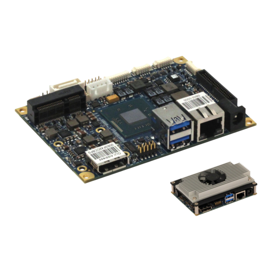
Introduction Introduction This manual describes the pITX-E38 boards made by KONTRON Technology A/S. In this manual the boards will also be denoted E38. The E38 boards are based on Intel Atom E38xx SoC (System on Chip) “Intel Bay Trail” and will be available in three versions. -
Page 9: Installation Procedure
Installation Procedure Installing the Board To get the board running follow these steps. If the board shipped from KONTRON has already components like RAM and CPU cooler mounted, then relevant steps below can be skipped. 1. Turn off the PSU (Power Supply Unit) Warning: Turn off PSU (Power Supply Unit) completely (no mains power connected to the PSU) or leave the Power Connectors unconnected while configuring the board. -
Page 10: Requirements Iec60950
Explosionsfara vid felaktigt batteribyte. Använd samma Paristo voi räjähtää, jos se on virheellisesti asennettu. batterityp eller en ekvivalent typ som rekommenderas av Vaihda paristo ainoastaan lalteval- mistajan apparattillverkaren. Kassera använt batteri enligt suosittelemaan tyyppiln. Hävitä käytetty paristo fabrikantens instruktion. valmistajan ohjeiden mukaisesti. pITX-E38 Users Guide... -
Page 11: System Specifications
Memory 1x DDR3L SODIMM socket supporting single-channel unbuffered DDR3L 1066/1333MHz (PC3-8500/PC3-10600). pITX-E3815/E3826 supports only DDR3-1066MHz. Up to 4GB (Intel specification) however Kontron has qualified 8GB. (ECC not supported). 1x Gbe LAN Intel I210 ”Springville” DP (DisplayPort) v1.1a Intel® Gen7 Graphics, OpenGL 3.0, OpenCL 1.2, DX11, H.264, MPEG2, MCV, VC-1, VP8 LVDS LVDS panels up to 2 pixels per clock, 24 bit colors (VESA/JEIDA). - Page 12 414.670 / 183.190 hours @ 40°C / 75°C. Note that these values are without the active cooler used on the pITX-E3845 (see next page). Restriction of Hazardous Substances (RoHS): All boards in the pITX-E38 family are RoHS compliant. Capacitor utilization: Solid Capacitors with Conductive Polymer rated for 105 °C used on board.
- Page 13 Note that Intel specifies that battery must be connected, however it is unspecified what is the risk of not using battery. When battery is not connected, Kontron has not been able to find any problems except for RTC not running.
-
Page 14: System Overview
KTD-N0904-E Page 11 System Specification System overview The block diagram below shows the architecture and main components of the pITX-E38. The key component ® on the board is the Intel Atom E38xx SoC (Bay Trail). SODIMM DDR3L 1066/1333 Intel DP (DisplayPort 1.1), 1 slot 1-8GB. -
Page 15: System Memory Support
P/N will be maintained so that EOL module will be replaced by other similar type of qualified module. As a minimum it is recommend using Kontron memory modules for prototype system(s) in order to prove stability of the system and as for reference. -
Page 16: Power Consumption
1130mA - 5.65W 1250mA - 6.25W S3 Mode 247mA - 1.235W 255mA - 1.275W 266mA - 1.33W S4 Mode 239mA - 1.195W 238mA - 1.19W 236mA - 1.18W S5 Mode 214mA - 1.070W 219mA - 1.095W 228mA - 1.14 pITX-E38 Users Guide... -
Page 17: Connector Locations
KTD-N0904-E Page 14 Connector Locations Connector Locations pITX-E38 - frontside On the backside: GPIO SODIMM MicroSD Card Slot System Temp. Sensor XDP (unsupported) SBC connector Always On SBC-Ext-Bat SBC-GPIO Clear CMOS COM2 COM1 SATA0 USB3 USB2 Audio mPCIe mSATA +5Vin Int. -
Page 18: Pitx-E38 - Backside
KTD-N0904-E Page 15 Connector Locations pITX-E38 - backside System Temp. Sensor MicroSD Card SODIMM XDP (unsupported) pITX-E38 Users Guide... -
Page 19: Connector Definitions
On-board pull-up or pull-down resistors on input pins or open-collector output pins. Note Special remarks concerning the signal. The abbreviation TBD is used for specifications which are not available yet or which are not sufficiently specified by the component vendors. pITX-E38 Users Guide... -
Page 20: Io-Area Connectors
Aux Channel (-) AUX (-) channel used by DP Aux Ch (n) or DDC Data DDC Data used by HDMI Hot Plug Internally pull down (100Kohm). Return Same as GND 3.3V Fused by 1.5A resetable PTC fuse. pITX-E38 Users Guide... -
Page 21: Ethernet Connector
IO-Area Connectors Ethernet Connector The pITX-E38 support single channels of 10/100/1000Mb Ethernet based on Intel® Springville i210. In order to achieve the specified performance of the Ethernet port, Category 5 twisted pair cables must be used with 10/100MB and Category 5E, 6 or 6E with 1Gb LAN networks. -
Page 22: Usb Connectors (Io Area)
IO-Area Connectors USB Connectors (IO Area) The pITX-E38 board contains support for 1 USB3.0/2.0 port (Lower USB port, USB0) and one USB2.0 port (higher USB port, USB1) in the IO area. USB 2.0 ports allowing data transfers up to 480Mb/s. The USB 3.0 port allowing data transfers up to 5Gb/s. - Page 23 Differential pair works as serial differential receive/transmit data lines. TXn+ TXn- (n= 0,1) 5V supply for external devices. SB5V is supplied during power-down to allow wakeup 5V/SB5V on USB device activity. Protected by 1.0A current limiting circuit for each USB port. pITX-E38 Users Guide...
-
Page 24: Dc Power Jack Connector (5Vin Ext.)
To protect the external power lines of peripheral devices make sure that Notes: - the wires have the right diameter to withstand the maximum available current. - to enclosure of the peripheral device fulfills the fire-protecting conditions of IEC/EN 60950. pITX-E38 Users Guide... -
Page 25: Internal Connectors
Maximum allowed current on each pin is 3A. Available cable kit: 1055-8061 Cable Power 4p 30cm OE pITX-E38 Fan Connector (Fan) The Fan can be used to actively cool the heatsink mounted on the board. The fan rotation speed can be monitored and the fan speed controlled by the temperature of the PCB (near SoC). -
Page 26: Lvds Flat Panel Connector (Lvds)
If the Backlight Enable is required to be active high then, check the following BIOS Chipset setting: Backlight Signal Inversion = Enabled. Available cable kit: 821515 Open End LVDS Cable 572mm pITX-E38 Users Guide... -
Page 27: Sata (Serial Ata) Disk Interface (Sata0)
Ioh/Iol Note SATA* TX+ SATA* TX- SATA* RX- SATA* RX+ Signal Description SATA0 RX+ / RX- Host transmitter differential signal pair Host receiver differential signal pair SATA0 TX+ / TX- Available cable kit: PN 96079-0000-00-1 Cable SATA 500mm pITX-E38 Users Guide... -
Page 28: Usb Connectors (Usb2 And Usb3)
IO-Area Connectors USB Connectors (USB2 and USB3) The pITX-E38 support two internal USB 2.0 ports (USB2 and USB3) allowing data transfers up to 480Mb/s. Legacy Keyboard/Mouse and wakeup from sleep states are supported. Over-current detection on all fourteen USB ports is supported. -
Page 29: Serial Com1 - Com2 Ports (Com1, Com2)
Clear To Send, indicates that the modem or data set is ready to exchange data. Available cable kit: 1055-8059 Cable Serial 5p 20cm OE pITX-E38 For more detailed information how to set up the COM ports please find KTD-N0914 “pITX-E38 COM port Application Note” on EMD Customer Section http://emdcustomersection.kontron.com/wp- login.php?redirect_to=/... -
Page 30: Audio Connector
3.3V signal via 220 ohm resistor pullup to 3.3V. SATA_LED# SATA Activity LED (active low signal). 3V3 output when passive. SUS_LED Suspend Mode LED (active high signal). Output 3.3V via 220Ω. Available cable kit: 1055-8065 Cable Frontpanel 10p 20cm OE pITX-E38 pITX-E38 Users Guide... -
Page 31: Battery Module
GPIO7 Ground Available cable kit: 1055-8063 Cable GPIO 10p 20cm OE pITX-E38 SBC Connector (SBC-Connector) The SBC connector is present on the Battery Module and used to interface the Battery Module to the SBC. Note Pull U/D Ioh/Iol Type Signal... -
Page 32: Sbc-Gpio Connector (Sbc-Gpio)
Note that Intel specifies that battery must be connected, however it is unspecified what is the risk of not using battery. When battery is not connected, Kontron has not been able to find any problems except for RTC not running. -
Page 33: Always On" (Always On)
Quad Output Fast Read modes. The signal is not used in Dual Output Fast Read mode. SPI Data I/O: A bidirectional signal used to support Dual IO Fast Read, Quad IO Fast Read SPI_IO3_#HOLD and Quad Output Fast Read modes. The signal is not used in Dual Output Fast Read mode. pITX-E38 Users Guide... -
Page 34: Xdp (Xdp)
Type Pull Up/Down Note OBSFN_A0 220R to 1,8V OBSFN_A1 HOOK0 PMC_RSMRST# HOOK1 PWRBTN# HOOK2 PMC_CORE_PWROK HOOK3 XDP_RTEST# HOOK4 HOOK5 +1,8V HOOK6 PLTRST# HOOK7 1,8V_SYS_RESET# 50R to 1,8V TRST# /50R 50R to 1,8V 50R to 1,8V TCK0 /50R pITX-E38 Users Guide... -
Page 35: Slot Connectors (Mpcie, Msata, Microsd Card)
+3V3 Dual CLK_MPCIE DATA_MPCIE +1.5V RST_MPCIE# SEL_MSATA +3V3 Dual Note 1: 10K ohm pull-up to 3V3. Note 2: 2K2 ohm pull-up to 3V3 Dual. Note 2: 10K ohm pull-down to GND. Recommended fixing tool is “Richco MDLSP1-08M-01” http://portal.richco-inc.com/login pITX-E38 Users Guide... -
Page 36: Microsd Card Slot
Card detect / Data bit 3 IO-3.3 Command line IO-3.3 Ground VCC3 Power +3.3V Clock O-3.3 Ground DATA0 Data bit 0 IO-3.3 DATA1 Data bit 1 IO-3.3 DATA2 Data bit 2 IO-3.3 Card Detection on low Write Protect pITX-E38 Users Guide... -
Page 37: On-Board - & Mating Connector Types
The Mating connector(s) / Cable Kits(s) which are fitting the On-board connectors are listed in below table. The highlighted cable kits are included in the “pITX-E38 Cable & Driver Kit” PN 1056-2142 / 1000000021 (Different quantity of each cable kit included, depending on the quantity of onboard connectors). -
Page 38: 10 Bios
Blue text for functions (not all can be modified). Black background for actual selection. Black text actual settings. The following table describes the changeable settings: Feature Options Description System Date MM/DD/YYYY Set the system date. System Time HH:MM:SS Set the system time. pITX-E38 Users Guide... -
Page 39: System Information
Intel ® Atom ™ CPU E3845 @ 1.91GHz 1.926 GHz Processor Speed System Memory Speed 1333 MHz L2 C→che RAM 2048 KB Total Memory 4096 MB Help Select Item Change Values Setup Defaults ► Exit Select Menu Enter Select Sub-Menu Save and Exit pITX-E38 Users Guide... -
Page 40: Boot Features
Allow Hotkey in S4 resume UEFI Boot [En→↓led] [En→↓led] Legacy Boot [Dis→↓led] Boot in Legacy Video Mode Lo→d OPROM [All] Help Select Item Change Values Setup Defaults ► Exit Select Menu Enter Select Sub-Menu Save and Exit pITX-E38 Users Guide... - Page 41 Load all OPROMs or on demand according to the boot Load OPROM device. On Demand Note 1: Use either digit keys to enter value (0 – 99) or +/- keys to increase/decrease value. pITX-E38 Users Guide...
-
Page 42: Boot Features
UEFI PXE Boot Priority Set the priority of UEFI PXE Boot. IPv4 First Note2 Note1: Only shown if Network Stack is enabled. Note2: Only shown if Network Stack is enabled and greyed if not both IPv4 and IPV6 are enabled. pITX-E38 Users Guide... -
Page 43: Advanced
English Select Language Select Language. Francais Etc. Windows OS Selection OS Selection Linux Note: OS Selection must be set in according to the requested OS to boot. If incorrect OS Selection then system will not boot correctly. pITX-E38 Users Guide... -
Page 44: Cpu Configuration
Execute Disable Bit prevent certain classes of Disable Execute Disable Bit mailicious buffer overflow attacks when Enable combined with a supporting OS. Disable AESNI AESNI. Enable Disable Limit CPUID Maximum Disabled for Windows XP. Enable Disabled Enabled/Disable Digital Thermal Sensor. Enabled pITX-E38 Users Guide... - Page 45 Enable/Disable C1E, C2E and C4E. When Disabled Enhanced C-states enabled, CPU will switch to minimum speed Enabled when all cores enter C-State. This option controls the Max C State that the Max C State processor will support. pITX-E38 Users Guide...
-
Page 46: Uncore Configuration
[64M] Spread Spectrum clock [Disable] IGD – LCD Control [Auto] LCD Panel Type [Auto] IGD Boot Type [Auto] Panel Scaling Help Select Item Change Values Setup Defaults ► Exit Select Menu Enter Select Sub-Menu Save and Exit pITX-E38 Users Guide... - Page 47 IGD Boot Type DP PortB=EFP1 DP Port C DP PortC=EFP2 eDP=LFP1 DSI Port A DSI PortA=LFP2 DSI Port C DSI PortC=LFP2 Auto Select the LCD panel scaling option used by Panel Scaling Centering Internal Graphics Device. Stretching pITX-E38 Users Guide...
-
Page 48: Lan Configuration
Save and Exit Note: The “+” and “-“(to the right of the MAC address) indicates respectively if link is established or not. Function Selection Description Disabled Enabled ETH1 Configuration Control the Ethernet Devices and PXE boot. With PXE boot pITX-E38 Users Guide... -
Page 49: Hardware Monitor
Fan speed at trip point in %. Minimum value 30, 31, …, 50, …, 100 Trip Point Speed is 30. The number of pole pairs inside the fan. Ex: Fan Poles Fan poles=4 generates 2 pulses every one rotation. pITX-E38 Users Guide... -
Page 50: Display Configuration
Name of panel to select. 3,3V Panel VCC VCC of panel selected panel. Backlight Enable Active Inversion of backlight signal. High Note1: Depend on Resolution and Manufacture combination. If combination does’nt exist then Panel name is N/A (Not Available). pITX-E38 Users Guide... -
Page 51: South Cluster Configuration
PCI Express Configuration Settings. ► USB Configuration ► Audio Configuration ► SATA Drives ► LPSS & SCC Configuration ► Miscellaneous Configuration Help Select Item Change Values Setup Defaults ► Exit Select Menu Enter Select Sub-Menu Save and Exit pITX-E38 Users Guide... - Page 52 Gen1 Gen2 Auto PCIe 2 Speed Gen1 Configure PCIe Speed. Gen2 Enable PCI Express Root Port 2 Control the PCI Express Root Port. Disable Enable PCI Express Root Port 2 Control the PCI Express Root Port. Disable pITX-E38 Users Guide...
- Page 53 Control each of the USB ports (0~3) disabling. Enable Disable USB Port #0 Disable USB port. Enable Disable USB Port #1 Disable USB port. Enable Disable USB Port #2 Disable USB port. Enable Disable USB Port #3 Disable USB port. Enable pITX-E38 Users Guide...
- Page 54 Selection Description Control Detection of the Azalia device. Disabled = Azalia will be unconditionally Disable Audio Controller disabled. Enable Enabled = Azalia will be unconditionally Enabled. Disable Azalia HDMI Codec Enable/Disable internal HDMI codec for Azalia. Enable pITX-E38 Users Guide...
- Page 55 If enabled, SATA port will be reported as Hot SATA Port 0 Hot Plug Capability Plug capable. Note: Requires hardware support. Enabled Disabled If enabled, SATA port will be reported as Hot SATA Port 1 Hot Plug Capability Enabled Plug capable. Note: Requires hardware support. pITX-E38 Users Guide...
- Page 56 SCC SD Card Support Enable\Disable. Enable Disable SD SDR 25 Support Enable Disable SD SDR 50 Support Enable Disable LPSS HSUART #1 Support LPSS HSUART #1 Support Enable\Disable. Enable Disable LPSS HSUART #2 Support LPSS HSUART #2 Support Enable\Disable. Enable pITX-E38 Users Guide...
- Page 57 Example of mSATA modules working with the setting mPCIE: SanDisk X110 mSATA SSD - 128GB (SD6SF1M-128G-1022) Examples of mSATA modules working with the setting mSATA: Transcend MSA370 (TS64GMSA370) Apacer APSDM016GM5PN-PCM (0 °C to 70 °C) Apacer APSDM016GM5PN-PCMW (-40 °C to 85 °C) pITX-E38 Users Guide...
-
Page 58: Security Configuration
Exit Select Menu Enter Select Sub-Menu Save and Exit Function Selection Description Disabled Enabled Disabled TXE HMRFPO Enabled Disabled TXE Firmware Update Enabled Disabled TXE EOP Message Send EOP Message Before Enter OS Enabled TXE Unconfiguration Perform pITX-E38 Users Guide... -
Page 59: Thermal
87 C, 90 C Disable DPFT Enable/Disable DPTF. Enable Disable Charger Participant Enable/Disable Charger Participant Device. Enable Disable Display Participant Enable/Disable Display Participant Device. Enable Disable Power Participant Enable/Disable Power Participant Device. Enable pITX-E38 Users Guide... -
Page 60: Security
Set or clear the Supervisor account’s password. Supervisor Hint String (up to 20 characters) Press Enter to type Supervisor Hint String. Set the minimum number of characters for Min. password length 1, 2, …, 20 password (1-20). pITX-E38 Users Guide... -
Page 61: Boot
‘Del’ deletes an 6. USB CD: unprotected device. 7. USB FDD: 8. SD Card1: 9. Internal Shell: Help Select Item Change Values Setup Defaults ► Exit Select Menu Enter Select Sub-Menu Save and Exit pITX-E38 Users Guide... -
Page 62: Exit
Load Setup Defaults Equal to F9. Load standard defaults values. Discard Changes Load the original value of this boot time. Not the default Setup value. Save Changes Save all changes of all menus, but do not reset system. pITX-E38 Users Guide... - Page 63 Our company network supports you worldwide with offices in Germany, Austria, Switzerland, Great Britain and the USA. For more information please contact: FORTEC Elektronik AG FORTEC Elektronik AG Hauptniederlassung Büro West Lechwiesenstr. 9 Hohenstaufenring 55 86899 Landsberg am Lech 50674 Köln Telefon: +49 (0) 8191 91172-0 Telefon:...
Need help?
Do you have a question about the pITX-E38 and is the answer not in the manual?
Questions and answers