
Related Manuals for Kontron mITX-DNV


Summary of Contents for Kontron mITX-DNV
- Page 1 USER GUIDE mITX-DNV Doc. User Guide, Rev. 1.0 Doc. ID: [To be Determined] www.kontron.com // 1...
- Page 2 - User Guide, Rev. 1.0 This page has been intentionally left blank www.kontron.com // 2...
- Page 3 In cases of doubt, please contact Kontron. This user guide is protected by copyright. All rights are reserved by Kontron. No part of this document may be reproduced, transmitted, transcribed, stored in a retrieval system, or translated into any language or computer language, in any form or by any means (electronic, mechanical, photocopying, recording, or otherwise), without the express written permission of Kontron.
- Page 4 ENVIRONMENTAL DAMAGE (COLLECTIVELY, "HIGH RISK APPLICATIONS"). You understand and agree that your use of Kontron devices as a component in High Risk Applications is entirely at your risk. To minimize the risks associated with your products and applications, you should provide adequate design and operating safeguards.
-
Page 5: Revision History
If you have any difficulties using this user guide, discover an error, or just want to provide some feedback, contact Kontron support. Detail any errors you find. We will correct the errors or problems as soon as possible and post the revised user guide on our website. -
Page 6: Symbols
- User Guide, Rev. 1.0 Symbols The following symbols may be used in this user guide DANGER indicates a hazardous situation which, if not avoided, will result in death or serious injury. WARNING indicates a hazardous situation which, if not avoided, could result in death or serious injury. -
Page 7: For Your Safety
Therefore, in the interest of your own safety and of the correct operation of your new Kontron product, you are requested to conform with the following guidelines. -
Page 8: Lithium Battery Precautions
General Instructions on Usage In order to maintain Kontron’s product warranty, this product must not be altered or modified in any way. Changes or modifications to the product, that are not explicitly approved by Kontron and described in this user guide or received from Kontron Support as a special handling instruction, will void your warranty. -
Page 9: Table Of Contents
- User Guide, Rev. 1.0 Table of Contents Symbols ..........................................6 For Your Safety ........................................7 High Voltage Safety Instructions .................................. 7 Special Handling and Unpacking Instruction ............................7 Lithium Battery Precautions ..................................8 General Instructions on Usage ..................................8 Quality and Environmental Management .............................. -
Page 10: List Of Tables
- User Guide, Rev. 1.0 7.10. mPCIe / mSATA Socket (MPCIE1) ..............................45 7.11. SIM Interface Wafer for MPCIE1 (CN4) ............................47 7.12. PCIE x8 Socket (PCIE1) ..................................48 7.13. GbE LAN LED Header (CN2) ................................. 50 7.14. Wireless Activity LED Header for MPCIE1 (CN5) ........................... 51 7.15. -
Page 11: List Of Figures
Table 51: Main Setup Menu Sub-Screens and Functions ........................59 Table 52: List of Acronyms ................................... 84 List of Figures Figure 1: System Block Diagram mITX-DNV ............................. 17 Figure 2: Top Side ......................................22 Figure 3: Connector Panel Side ................................... 24 Figure 4: VGA Connector CN24 .................................. - Page 12 - User Guide, Rev. 1.0 Figure 24: Wireless Activity LED Header CN5 ............................51 Figure 25: General Purpose LED Wafer CN25 ............................51 Figure 26: Programming example 1 ................................52 Figure 27: Programming example 2 ................................52 Figure 28: Jumper Connector ..................................53 Figure 29: mPCIe / mSATA Selection JP1 ..............................
-
Page 13: 1/ Introduction
- User Guide, Rev. 1.0 1/ Introduction This user guide describe the mITX-DNV board made by Kontron. This board will also be denoted mITX-DNV within this user guide. Use of this user guide implies a basic knowledge of PC-AT hardware and software. This user guide focuses on describing the mITX-DNV board's special features and is not intended to be a standard PC-AT textbook. -
Page 14: 2/ Installation Procedures
Handle the board only by the edges To get the board running follow these steps. If the board shipped from KONTRON already has components like RAM and CPU cooler mounted, then skip the relevant steps below. Turn off the PSU (Power Supply Unit) Turn off PSU (Power Supply Unit) completely (no mains power connected to the PSU) or leave the Power Connectors unconnected while configuring the board. -
Page 15: Chassis Safety Standards
> 7 mm. Do not use washers with teeth, as they can damage the PCB and cause short circuits. 2.2. Chassis Safety Standards Before installing the mITX-DNV in the chassis, users must evaluate the end product to ensure compliance with the requirements of the IEC60950-1 safety standard: ... - Page 16 - User Guide, Rev. 1.0 Vaihda paristo ainoastaan lalteval- mistajan suosittelemaan tyyppiln Hävitä käytetty paristo valmistajan ohjeiden mukaisesti www.kontron.com // 16...
-
Page 17: 3/ System Specifications
- User Guide, Rev. 1.0 3/ System Specifications 3.1. System Block Diagram Figure 1: System Block Diagram mITX-DNV www.kontron.com // 17... -
Page 18: Component Main Data
- User Guide, Rev. 1.0 3.2. Component Main Data The table below summarizes the features of the mITX-DNV single board computer. Table 1: Component Main Data System Processor Intel® Denverton SoC Processors, Atom™ C3000 Series Memory Up to 2x DDR4 UDIMM memory socket... -
Page 19: Environmental Conditions
The mITX-DNV is designed to support Intel® Denverton Processors, Atom™ C3000 Series. The BGA CPU is remounted from factory. Kontron has defined the board versions as listed in the following table, so far all based on Embedded CPUs. Other versions are expected at a later date. -
Page 20: System Memory Support
Memory modules have in general a much lower longevity than embedded motherboards, and therefore EOL of modules can be expected several times during lifetime of the motherboard. As a minimum it is recommend using Kontron memory modules for prototype system(s) in order to prove stability of the system and as for reference. -
Page 21: Power Supply
- User Guide, Rev. 1.0 Display Max. Resolution (Px) at 60 Hz 1024 x 768 3.8. Power Supply In order to ensure safe operation of the board, the input power supply must monitor the supply voltage and shut down if the supply is out of range – refer to the actual power supply specification. Please note, in order to keep the power consumption to a minimal level, boards do not implement a guaranteed minimum load. -
Page 22: 4/ Connector Locations
- User Guide, Rev. 1.0 4/ Connector Locations 4.1. Top Side Figure 2: Top Side 11 12 13 14 15 16 Table 8: Jumper List Item Designation Description See Chapter mPCIE / mSATA Selection for MPCIE1 7.16.1 USB Power Selection 7.16.2... - Page 23 - User Guide, Rev. 1.0 Item Designation Description See Chapter FAN2 System FAN Wafer SATA1 SATA Port-1 Connector SATA2 SATA Port-2 Connector SATA3 SATA Port-3 Connector SATA4 SATA Port-4 Connector SATA5 SATA Port-5 Connector SATA6 SATA Port-6 Connector CN17 USB2.0 Port-1, 2 Header...
-
Page 24: Connector Panel Side
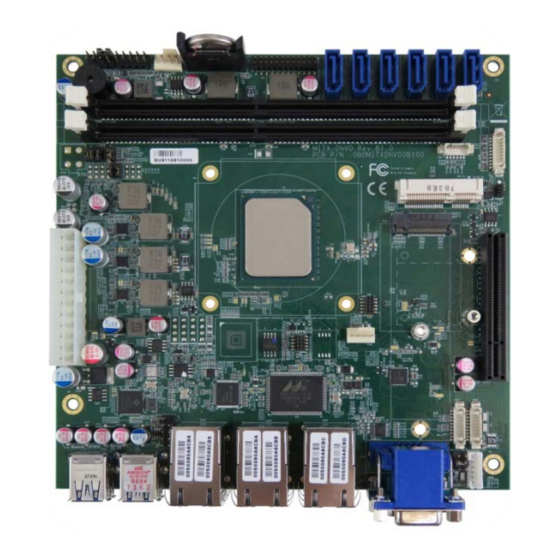
- User Guide, Rev. 1.0 4.2. Connector Panel Side Figure 3: Connector Panel Side Table 10: Connector Panel Side Connector List Item Designation Description See Chapter CN18 GbE LAN1, 2 RJ45 Connector CN19 GbE LAN3, 4 RJ45 Connector CN20... -
Page 25: 5/ Connector Definitions
- User Guide, Rev. 1.0 5/ Connector Definitions The following defined terms are used within this user guide to give more information concerning the pin assignment and to describe the connector's signals. Defined Term Description Shows the pin numbers in the connector... -
Page 26: 6/ I/O-Area Connectors
- User Guide, Rev. 1.0 6/ I/O-Area Connectors 6.1. VGA Connector (CN24) The external I/O connector panel supports one DB-15 VGA female port. Figure 4: VGA Connector CN24 Table 11: Pin Assignment VGA Connector CN24 Signal Description Analogue output carrying the red colour values. (75 Ohm cable impedance). -
Page 27: Ethernet Connectors (Cn18, Cn19 & Cn20)
- User Guide, Rev. 1.0 6.2. Ethernet Connectors (CN18, CN19 & CN20) The mITX-DNV supports six channels of 10/100/1000 Mbit Ethernet, which are based Intel® I210-AT (LAN1 & LAN2 (CN18)) and Marvell® 88E1543 (LAN3 & LAN4 (CN19), LAN5 & LAN6 (CN20)) controllers respectively. -
Page 28: Usb Connectors (I/O Area)
- User Guide, Rev. 1.0 6.3. USB Connectors (I/O Area) The external I/O connector panel supports two dual USB 3.0 connectors. USB3.0 ports are backward compatible with USB2.0. Figure 6: USB 3.0 Connector CN22, CN23 Table 13: Pin Assignment USB3.0 / USB2.0 Connector CN22, CN23... -
Page 29: Table 14: Signal Description
- User Guide, Rev. 1.0 Table 14: Signal Description Signal Description USBn_TX+, USBn_TX-, Differential pair works as serial differential receive/transmit data lines. USBn_RX+, USBn_RX-, (n= A, B) USBn_D-, USBn_D- +USBn_VCC 5 V supply for external devices. VCC is supplied during power-down to allow wakeup on USB device activity. -
Page 30: Rs232/422/485 Com1 Connector (Cn26)
- User Guide, Rev. 1.0 6.4. RS232/422/485 COM1 Connector (CN26) The external I/O connector panel supports one DB9 RS232/422/485 port. Figure 9: RS232/422/485 COM1 Connector CN26 Table 15: Pin Assignment RS232/422/485 COM1 Connector CN26 RS232 Signal RS422 Signal RS485 Signal... -
Page 31: 7/ Internal Connectors
7/ Internal Connectors 7.1. Power Input Wafer (ATX1) The mITX-DNV boards are designed to be supplied from a standard ATX power supply. Hot plugging any of the power connector is not allowed. Hot plugging might damage the board. In other words, turn off main supply etc. to make sure all the power lines are turned off when connecting to the motherboard. -
Page 32: Table 18: Signal Description
- User Guide, Rev. 1.0 Signal Description Ground Table 18: Signal Description Signal Description POWER OK POWER_OK is a power good signal and should be asserted high by the power supply to indicate that the +5VDC and +3.3VDC outputs are above the undervoltage thresholds of the power supply. -
Page 33: Cpu / System Fan Wafer (Fan1 & Fan2)
- User Guide, Rev. 1.0 7.2. CPU / System Fan Wafer (FAN1 & FAN2) The CPU Fan Wafer (FAN1) is used for the connection of the Fan for the CPU. The System Fan Wafer (FAN2) can be used to power, control and monitor a fan for chassis ventilation etc. -
Page 34: Sata (Serial Ata) Port 1 ~ Port 6 Connector (Sata1 ~ Sata6)
- User Guide, Rev. 1.0 7.3. SATA (Serial ATA) Port 1 ~ Port 6 Connector (SATA1 ~ SATA6) The SATA connectors supply the data connection for the SATA hard disk and is SATA 3.0 compatible. Figure 12: SATA Port 1 ~ Port 6 Connector SATA1 ~ SATA6... -
Page 35: Usb Connectors (Internal) (Cn17)
- User Guide, Rev. 1.0 7.4. USB Connectors (Internal) (CN17) The USB port pin header CN17 supports two USB 2.0 ports. Figure 13: USB 2.0 Port 1, 2 Pin Header CN17 Table 24: Pin Assignment CN5 Signal Note +USBVCC... -
Page 36: Front Panel Pin Header (Fp1 & Fp2)
- User Guide, Rev. 1.0 7.5. Front Panel Pin Header (FP1 & FP2) Figure 14: Front Panel 1 Pin Header FP1 RSTBTN SPKR HLED Table 26: Pin Assignment FP1 Signal Note Reset Button + Speaker + Reset Button -... -
Page 37: Table 29: Signal Description
- User Guide, Rev. 1.0 Signal Note Power Button + Power Button - Power LED - SM_ALERT# BAT_LOW# SMBus Data SMBus Clock Table 29: Signal Description Signal Description Power LED - System Power LED. The power LED lights up when users turn on the system power, and blinks when the system is in sleep mode. -
Page 38: Serial Com2 Ports (Cn16)
- User Guide, Rev. 1.0 7.6. Serial COM2 Ports (CN16) Figure 16: Serial COM CN16 Table 30: Pin Assignment CN16 RS232 Signal RS422 Signal Half Duplex Full Duplex Note RS485 Signal RS485 Signal DATA- DATA+ The COM ports need to install an OS patch from ITE. The patch is only available for Windows and is not available Linux. - Page 39 - User Guide, Rev. 1.0 Signal Description RX+/- Received Data differential pair receives data from the communications link. Power Supply GND signal www.kontron.com // 39...
-
Page 40: Digital Input / Output Wafer (Cn15)
- User Guide, Rev. 1.0 7.7. Digital Input / Output Wafer (CN15) Figure 17: Digital Input / Output Wafer CN15 Table 32: Pin Assignment CN15 Signal Note DIO_0 DIO_1 DIO_2 DIO_3 DIO_4 DIO_5 DIO_6 DIO_7 www.kontron.com // 40... -
Page 41: Ps/2 Keyboard And Mouse Wafer (Cn21)
- User Guide, Rev. 1.0 7.8. PS/2 Keyboard and Mouse Wafer (CN21) Attachment of a PS/2 keyboard / mouse can be done through the pinrow connector CN21. Both interfaces utilize open-drain signalling with on-board pull-up. Figure 18: PS/2 Keyboard / Mouse Wafer CN21... -
Page 42: Key-B Ssd Slot (M2B1)
- User Guide, Rev. 1.0 7.9. M.2 Key-B SSD Slot (M2B1) The mITX-DNV supports M.2 modules in format 2242 with Key B. The M.2 specification enables one SATA3.0 (6 Gb/s) SSD socket to be exposed. Figure 19: M.2 Key-B SSD Slot M2B1 SATA M.2 requires the following BIOS depending on the class code options below. - Page 43 - User Guide, Rev. 1.0 Signal Note SATA_RX+ SATA_RX- SATA_TX- SATA_TX+ www.kontron.com // 43...
- Page 44 - User Guide, Rev. 1.0 Signal Note +3.3V +3.3V +3.3V www.kontron.com // 44...
-
Page 45: Mpcie / Msata Socket (Mpcie1)
- User Guide, Rev. 1.0 7.10. mPCIe / mSATA Socket (MPCIE1) Full-sized Mini-PCI Express V1.2 socket (MPCIE1). Socket MPCIE1 supports mPCIe, mSATA, USB2.0 and SIM-card socket. The SIM-card socket makes it possible to use a 3G/4G-wireless modem in this mPCIe slot. The USB does support WAKE function. - Page 46 - User Guide, Rev. 1.0 Signal Note Ground Ground +1.5V Ground SMB_CLK PETn0 / SATA_TX-* SMB_DATA PETp0 / SATA_TX+* Ground Ground USB_D- Ground USB_D+ +3.3VSB / +3.3V* Ground +3.3VSB / +3.3V* LED_WWAN# Ground / NC* LED_WLAN# Reserved LED_WPAN# Reserved +1.5V...
-
Page 47: Sim Interface Wafer For Mpcie1 (Cn4)
- User Guide, Rev. 1.0 7.11. SIM Interface Wafer for MPCIE1 (CN4) Figure 21: SIM Interface Wafer CN4 Table 37: Pin Assignment CN4 Signal Description Note UIM_PWR Power +5V or +3.3V UIM_DATA Input or Output for serial data UIM_RESET... -
Page 48: Pcie X8 Socket (Pcie1)
- User Guide, Rev. 1.0 7.12. PCIE x8 Socket (PCIE1) The 8-lane (x8) PCI Express slot connector can be used for external PCI Express cards inclusive graphics card and dedicated TMDS passive card. The slot is located nearest the edge of the board. Maximum theoretical bandwidth using 8 lines is 8 GB/s. - Page 49 - User Guide, Rev. 1.0 Side B Connector Side A Connector Signal Description Signal Description Ground PERp1 Receiver Lane 1, differential pair Ground PERn1 PETp2 Transmitter Lane 2, Ground differential pair PETn2 Ground Ground PERp2 Receiver Lane 2, differential...
-
Page 50: Gbe Lan Led Header (Cn2)
- User Guide, Rev. 1.0 7.13. GbE LAN LED Header (CN2) Figure 23: GbE LAN LED Header CN2 Table 39: Pin Assignment CN2 Signal Description Note LAN1_LINK+ LAN1_LINK- LAN1_100# LAN1_1000# LAN2_LINK+ LAN2_LINK- LAN2_100# LAN2_1000# LAN3_LINK+ LAN3_LINK- LAN3_100# LAN3_1000# LAN4_LINK+... -
Page 51: Wireless Activity Led Header For Mpcie1 (Cn5)
- User Guide, Rev. 1.0 7.14. Wireless Activity LED Header for MPCIE1 (CN5) Figure 24: Wireless Activity LED Header CN5 Table 40: Pin Assignment CN5 Signal Description Note LED+ LED- 7.15. General Purpose LED Wafer (CN25) Figure 25: General Purpose LED Wafer CN25... -
Page 52: Figure 26: Programming Example 1
- User Guide, Rev. 1.0 Figure 26: Programming example 1 Programmed High for LED on GPLED# Figure 27: Programming example 2 Programmed Low for LED on GPLED# www.kontron.com // 52... -
Page 53: Switches And Jumpers
- User Guide, Rev. 1.0 7.16. Switches and Jumpers The product has several jumpers which must be properly configured to ensure correct operation. Figure 28: Jumper Connector For a three-pin jumper (see Figure 25), the jumper setting is designated “1-2” when the jumper connects pins 1 and 2. -
Page 54: At / Atx Power Mode Selection (Jp3)
- User Guide, Rev. 1.0 Jumper Position Description Pin 1-2 Pin 2-3 +5VSB “X” = Jumper set (short) and “-” = jumper not set (open) 7.16.3. AT / ATX Power Mode Selection (JP3) Figure 31: AT / ATX Power Mode Selection JP3... -
Page 55: Flash Security Override Selection (Jp11)
- User Guide, Rev. 1.0 Table 46: Pin Assignment JP10 Jumper Position Description Pin 1-2 Pin 2-3 Normal Clear CMOS “X” = Jumper set (short) and “-” = jumper not set (open) 7.16.6. Flash Security Override Selection (JP11) Figure 34: Flash Security Override Selection JP11... - Page 56 - User Guide, Rev. 1.0 Jumper Position Description Pin 1-2 Pin 3-4 Pin 5-6 +12V “X” = Jumper set (short) and “-” = jumper not set (open) www.kontron.com // 56...
-
Page 57: 8/ On-Board Connectors & Mating Connector Types
8/ On-Board Connectors & Mating Connector Types The Mating connectors / Cables are connectors or cable kits which are fitting the On-board connector. The cable kits marked with "*" are included in the "mITX-DNV Cable & Driver Kit". Table 49: On-Board Connectors & Mating Connector Types... -
Page 58: 9/ Bios
Supervisor Password (see Security menu), press <RETURN>, and proceed with step 5. 5. A setup menu will appear. The mITX-DNV uEFI BIOS setup program uses a hot key-based navigation system. A hot key legend bar is located on the bottom of the setup screens. -
Page 59: Setup Menus
- User Guide, Rev. 1.0 9.2. Setup Menus The Setup utility features shows six menus in the selection bar at the top of the screen: Main Advanced Power Boot Security Save & Exit The Setup menus are selected via the left and right arrow keys. -
Page 60: Figure 36: Bios Main Menu Screen System Data And Time
- User Guide, Rev. 1.0 Figure 36: BIOS Main Menu Screen System Data and Time BIOS SETUP UTILITY Main Advanced Power Boot Security Save & Exit Product Information Product Name mITX-DNV-C3538 BIOS Version R0.09 (x64) BIOS Build Date 03/12/2018 ME FW Version 0B:4.0.0.143... -
Page 61: Advanced Setup Menu
- User Guide, Rev. 1.0 9.2.2. Advanced Setup Menu The Advanced setup menu provides sub-screens and functions for advanced configurations. The following sub- screen functions are included in the menu: LAN Configuration FIA HSIO12 Configuration CPU Chipset Configuration ... -
Page 62: Figure 37: Bios Advanced Menu
- User Guide, Rev. 1.0 Figure 37: BIOS Advanced Menu BIOS SETUP UTILITY Main Advanced Power Boot Security Save & Exit Load Intel I210 UNDI [Disabled] Load X553 1GbE UNDI [Disabled] > FIA HSIO12 Configuration > CPU Chipset Configuration →... -
Page 63: Figure 38: Bios Advanced Menu - Fia Hsio12 Configuration
- User Guide, Rev. 1.0 Figure 38: BIOS Advanced Menu - FIA HSIO12 Configuration BIOS SETUP UTILITY Main Advanced Power Boot Security Save & Exit Flexible I/O Adapter HSIO12 Configuration HSIO12 I/O amount Full Avtive Lane 8:PCIE-C6139(VGA) [PCIE Enabled]... - Page 64 - User Guide, Rev. 1.0 Feature Option Description (Driven High)] cards that implement radio frequency applications. www.kontron.com // 64...
-
Page 65: Figure 39: Bios Advanced Menu - Cpu Chipset Configuration
- User Guide, Rev. 1.0 Figure 39: BIOS Advanced Menu - CPU Chipset Configuration BIOS SETUP UTILITY Main Advanced Power Boot Security Save & Exit CPU Chipset Configuration EIST [Enabled] Turbo Mode [Enabled] CPU C State [Enabled] → ←: Select Screen Active Processor Core ↑... -
Page 66: Figure 40: Bios Advanced Menu - Sata Configuration
- User Guide, Rev. 1.0 Figure 40: BIOS Advanced Menu - SATA Configuration BIOS SETUP UTILITY Main Advanced Power Boot Security Save & Exit SATA Configuration SATA Controller 0 [Enabled] SATA-0 Port Multiplier [Disabled] SATA Controller 1 [Enabled] SATA-1 Port Multiplier... -
Page 67: Figure 41: Bios Advanced Menu - Usb Configuration
- User Guide, Rev. 1.0 Figure 41: BIOS Advanced Menu - USB Configuration BIOS SETUP UTILITY Main Advanced Power Boot Security Save & Exit USB Configuration USB Devices: → ←: Select Screen 1 Keyboard, 2 Mice, 2 Hubs ↑ ↓: Select Item... -
Page 68: Figure 42: Bios Advanced Menu - Trsted Computing
- User Guide, Rev. 1.0 Figure 42: BIOS Advanced Menu - Trsted Computing BIOS SETUP UTILITY Main Advanced Power Boot Security Save & Exit Configuration Security Device Support [Disabled] NO Security Device → ←: Select Screen ↑ ↓: Select Item Enter: Select +/-: Change Opt. -
Page 69: Figure 43: Bios Advanced Menu - Network Stack Configuration
- User Guide, Rev. 1.0 Figure 43: BIOS Advanced Menu - Network Stack Configuration BIOS SETUP UTILITY Main Advanced Power Boot Security Save & Exit Network Stack Configuration LAN Boot I210-AT-1 [Disabled] → ←: Select Screen LAN Boot I210-AT-2 [Disabled] ↑... -
Page 70: Figure 44: Bios Advanced Menu - Dio Configuration
- User Guide, Rev. 1.0 Figure 44: BIOS Advanced Menu - DIO Configuration BIOS SETUP UTILITY Main Advanced Power Boot Security Save & Exit DIO Configuration User Configuration [Disabled] DIO_0* [Output High] DIO_1* [Output High] DIO_2* [Output High] DIO_3*... -
Page 71: Figure 45: Bios Advanced Menu - Super Io Configuration
- User Guide, Rev. 1.0 Figure 45: BIOS Advanced Menu - Super IO Configuration BIOS SETUP UTILITY Main Advanced Power Boot Security Save & Exit Super IO Configuration > Serial Port 1 Configuration → ←: Select Screen > Serial Port 2 Configuration ↑... -
Page 72: Figure 47: Bios Advanced Menu - Super Io Configuration - Serial Port 2 Configuration
- User Guide, Rev. 1.0 Feature Option Description Serial Port 1 Type [RS232], [RS422], Select an appropriate type for Serial Port 1. [RS485] RS485 Duplex Mode [Half Duplex], [Full Select an appropriate RS485 Duplex Mode. Duplex] RS485 Auto Flow [Disabled], [Enabled] Select whether to enable or disable RS485 Auto Flow Control. -
Page 73: Figure 48: Bios Advanced Menu - Serial Port Console Redirection
- User Guide, Rev. 1.0 Figure 48: BIOS Advanced Menu - Serial Port Console Redirection BIOS SETUP UTILITY Main Advanced Power Boot Security Save & Exit COM1 Console Redirection [Disabled] > Console Redirection Settings COM2 Console Redirection [Disabled] → ←: Select Screen >... -
Page 74: Figure 49: Bios Advanced Menu - Serial Port Console Redirection - Com1 / Com2 Console Redirection Settings
- User Guide, Rev. 1.0 Figure 49: BIOS Advanced Menu - Serial Port Console Redirection - COM1 / COM2 Console Redirection Settings BIOS SETUP UTILITY Main Advanced Power Boot Security Save & Exit COM1 Console Redirection Settings Terminal Type... -
Page 75: Figure 50: Bios Advanced Menu - Serial Port Console Redirection - Legacy Console Redirection Settings
- User Guide, Rev. 1.0 Figure 50: BIOS Advanced Menu - Serial Port Console Redirection - Legacy Console Redirection Settings BIOS SETUP UTILITY Main Advanced Power Boot Security Save & Exit Legacy Console Redirection Settings Redirection COM Port [COM1] →... -
Page 76: Figure 51: Bios Advanced Menu - Serial Port Console Redirection - Out-Of-Band Mgmt Port Console Redirection Settings
- User Guide, Rev. 1.0 Figure 51: BIOS Advanced Menu - Serial Port Console Redirection - Out-of-Band Mgmt Port Console Redirection Settings BIOS SETUP UTILITY Main Advanced Power Boot Security Save & Exit Out-of-Band Mgmt Port [COM1] Terminal Type... -
Page 77: Figure 52: Bios Advanced Menu - H/W Monitor
- User Guide, Rev. 1.0 Figure 52: BIOS Advanced Menu - H/W Monitor BIOS SETUP UTILITY Main Advanced Power Boot Security Save & Exit PC Health Status > Smart FAN Configuration CPU Temperature-DTS : +31 C CPU Temperature-Diode : +31 C... -
Page 78: Power Setup Menu
- User Guide, Rev. 1.0 9.2.3. Power Setup Menu The Power setup menu provides functions and a sub-screen for power configurations. The following sub-screen function is included in the menu: WatchDog Timer Configuration Figure 53: BIOS Power Setup Menu... -
Page 79: Figure 54: Bios Power Setup Menu - Watchdog Timer Configuration
- User Guide, Rev. 1.0 Figure 54: BIOS Power Setup Menu - WatchDog Timer Configuration BIOS SETUP UTILITY Main Advanced Power Boot Security Save & Exit WatchDog Timer Configuration WDT Function [Disabled] → ←: Select Screen ↑ ↓: Select Item Enter: Select +/-: Change Opt. -
Page 80: Boot Setup Menu
- User Guide, Rev. 1.0 9.2.4. Boot Setup Menu The boot setup menu lists the for boot device priority order, that is generated dynamically. Figure 55: BIOS Boot Setup Menu BIOS SETUP UTILITY Main Advanced Power Boot Security Save & Exit... -
Page 81: Security Setup Menu
The Security setup menu provides information about the passwords and functions for specifying the security settings. The passwords are case-sensitive. The mITX-DNV provides no factory-set passwords. If there is already a password installed, the system asks for this first. To clear a password, simply enter nothing and acknowledge by pressing <RETURN>. -
Page 82: Remember The Password
- User Guide, Rev. 1.0 9.2.5.1. Remember the password It is highly recommended to keep a record of all passwords in a safe place. Forgotten passwords results in being locked out of the system. If the system cannot be booted because the User Password or the Supervisor Password are not know, contact Kontron Support for further assistance. -
Page 83: Save & Exit Setup Menu
- User Guide, Rev. 1.0 9.2.6. Save & Exit Setup Menu The exit setup menu provides functions for handling changes made to the UEFI BIOS settings and the exiting of the setup program. Figure 57: BIOS Boot Setup Menu... -
Page 84: Appendix A: List Of Acronyms
- User Guide, Rev. 1.0 Appendix A: List of Acronyms The following table does not contain the complete acronyms used in signal names, signal type definitions or similar. A description of the signals is included in the I/O Connector and Internal connector chapters within this user guide. -
Page 85: About Kontron
Kontron is a listed company. Its shares are traded in the Prime Standard segment of the Frankfurt Stock Exchange and on other exchanges under the symbol "KBC". For more information, please visit: www.kontron.com...
Need help?
Do you have a question about the mITX-DNV and is the answer not in the manual?
Questions and answers