Table of Contents
Advertisement
Quick Links
Office: (800) 683-7248
Technical Support: (702) 651-3444
FAX: (702) 651-0214
E-Mail: techsupport@jcmglobal.com
Web-Site: www.jcmglobal.com
®
UBA
Series
ID =R3UBAGloBack+Pix+R.jpg
Universal Bill Acceptor
(UBA-1x-SS & UBA-x4-SS/SU)
Operation and Maintenance Manual
(Revision 3)
JCM Part No. 960-000097R_Rev. 3
© 2010, JCM American, Corporation
Advertisement
Table of Contents

Summary of Contents for JCM GLOBAL UBA Series
- Page 1 Office: (800) 683-7248 Technical Support: (702) 651-3444 FAX: (702) 651-0214 E-Mail: techsupport@jcmglobal.com Web-Site: www.jcmglobal.com ® Series ID =R3UBAGloBack+Pix+R.jpg Universal Bill Acceptor (UBA-1x-SS & UBA-x4-SS/SU) Operation and Maintenance Manual (Revision 3) JCM Part No. 960-000097R_Rev. 3 © 2010, JCM American, Corporation...
- Page 2 UBA® Series Universal Bill Acceptor (UBA-1x-SS & UBA-x4-SS/SU) Operation and Maintenance Manual REVISION HISTORY Rev №. Date Reason for Update Comment 6/16/05 Initial Version 10/26/06 Updated Initial Version 12/19/07 Updated Revision 1 Version Updated Revision 2 Version with Additional UBA14/24 & 25 2/23/10 Information JCM is a registered trademark of JCM American Corporation.
-
Page 3: Table Of Contents
UBA-1x-SS & UBA-x4-SS/SU Series Table of Contents Page 1 GENERAL INFORMATION.................. 1-1 Model/Type Number Specifications ................1-2 Precautions ........................1-2 User Cautions..........................1-2 UBA-10/11/12 Component Names ................1-3 UBA-14/24 Component Names................... 1-4 Specifications ......................1-5 Technical Specifications ......................1-5 Environmental Specifications ....................1-5 Electrical Specifications......................1-5 Structural Specifications ......................1-5 System Configuration .................... - Page 4 UBA-1x-SS & UBA-x4-SS/SU Series Table of Contents Continued Page Retrieving Banknotes ....................2-9 Clearing a Banknote Jam ..................2-10 Cleaning/Preventive Maintenance ................2-11 Available Cleaning Card ....................2-11 Card Features ............................2-11 Directions For Use ..........................2-11 UBA 10/11/12/14 & 24 Related Schematics ..............2-12 UBA Faceplate LED Lighting Control Circuit Schematic ............2-12 UBA Optional Conversion Board Interface Circuit Schematic ..........
- Page 5 UBA-1x-SS & UBA-x4-SS/SU Series Table of Contents Continued Page Transport C Timing Belt Disassembly......................... 4-9 Transport C Timing Belt Removal .....................4-9 Transport D Solenoid Removal ....................4-11 Cash Box Handle and Intelligent Cash Box ICB Module Unit Disassembly......4-11 Cash Box Handle Removal........................4-11 ICB Module Removal ..........................4-11 Cash Box Sensor Board Removal...................4-12 Pusher Mechanism Unit Disassembly..................4-12...
- Page 6 UBA-1x-SS & UBA-x4-SS/SU Series Table of Contents Continued Page Cash Box Unit Parts List ......................7-18 Face Unit Exploded View...................7-22 Faceplate Unit Parts List......................7-23 Optional Unit Parts List ......................7-23 8 INDEX ........................8-1 A TROUBLESHOOTING ..................A-1 Introduction ......................... A-1 Troubleshooting Overview ..................
- Page 7 UBA-1x-SS & UBA-x4-SS/SU Series List of Figures Page Figure 1-1 Universal Bill Acceptor (UBA-1x-SS & UBA-x4-SS/SU) ....... 1-1 Figure 1-2 Precautionary Symbols................. 1-2 Figure 1-3 Universal Bill Acceptor (UBA-1X-SS) Major Component Parts .... 1-3 Figure 1-4 Universal Bill Acceptor (UBA-X4-SS/SU) Major Component Parts ..1-4 Figure 1-5 UBA System Configuration..............
- Page 8 UBA-1x-SS & UBA-x4-SS/SU Series List of Figures Continued Page Figure 2-22 UBA-10/11/12-SS Bill Acceptor CPU Board Schematic Diagram ..2-13 Figure 2-23 UBA-14-SS Bill Acceptor CPU Board Schematic Diagram ....2-14 Figure 2-24 External Connector Interface Circuit........... 2-15 Figure 2-25 Bill Acceptor Operational Flowchart (Part 1) ........2-17 Figure 2-26 Bill Acceptor Operational Flowchart (Part 2) ........
- Page 9 UBA-1x-SS & UBA-x4-SS/SU Series List of Figures Continued Page Figure 4-35 Cash Box Handle Removal ..............4-11 Figure 4-36 ICB Module Removal................4-11 Figure 4-37 Cash Box Sensor Removal ..............4-12 Figure 4-38 Pusher Mechanism Unit Removal ............4-12 Figure 4-39 Pusher Mechanism Separation ............4-12 Figure 4-40 Cover Roller Removal ................
- Page 10 UBA-1x-SS & UBA-x4-SS/SU Series List of Figures Continued Page Figure 6-25 UBA-USB Tool Suite Opening Screen ..........6-8 Figure 6-26 UBA-USB Driver Install Screen ............6-8 Figure 6-27 Re-Opened UBA-USB Tool Suite Screen ........... 6-8 Figure 6-28 UBA-USB Tool Suite Standard Screen ..........6-9 Figure 6-29 UBA Downloader Program Screen............
- Page 11 UBA-1x-SS & UBA-x4-SS/SU Series List of Tables Page Table 1-1 Model Number Specifications..............1-2 Table 1-2 UBA-1x Technical Specification ............1-5 Table 1-3 UBA-1x Environmental Specification............. 1-5 Table 1-4 UBA-1x Electrical Specification ............. 1-5 Table 1-5 UBA-1x Structural Specification ............1-5 Table 1-6 Country Code Listings .................
- Page 12 UBA-1x-SS & UBA-x4-SS/SU Series List of Tables THIS PAGE INTENTIONALLY LEFT BLANK JCM Part No. 960-000097R_Rev. 3 © 2010, JCM American, Corporation...
-
Page 13: General Information
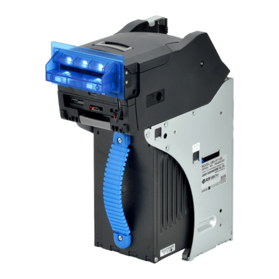
UBA® Series Universal Bill Acceptor (UBA-1x-SS & UBA-x4-SS/SU) S e c t i o n 1 1 GENERAL INFORMATION This section provides a general overview of the • Standard Cash Box Dimensions Universal Bill Acceptor Series (UBA-1x-SS & • Country Codes UBA-x4-SS/SU) pictured in Figure 1-1. -
Page 14: Model/Type Number Specifications
Section 1 Universal Bill Acceptor (UBA-1x-SS & UBA-x4-SS/SU) General Information Model/Type Number Specifications Precautions Table 1-1: Model Number Specifications Model: UBA - ** - S* - **0 - 00 - ***** - *** - ** (1,2) (3) (4,5,6) (7,8) (9,10,11,12,13) (14)(15) Sensor Configuration Type 1 Type 2... -
Page 15: Uba-10/11/12 Component Names
General Information Universal Bill Acceptor (UBA-1x-SS & UBA-x4-SS/SU) Section 1 Use a soft, lint-free cloth and a mild non- 11 of Section 2 of this Service Manual for abrasive soap and water solution to clean more information on using the Waffletech- dust and debris from the Banknote’s path. -
Page 16: Uba-14/24 Component Names
Section 1 Universal Bill Acceptor (UBA-1x-SS & UBA-x4-SS/SU) General Information UBA-14/24 Component Names Figure 1-3 illustrates the UBA-14/24 Primary Component Parts and their relative locations. Figure 1-4 Universal Bill Acceptor (UBA-X4-SS/SU) Major Component Parts © 2010, JCM American, Corporation JCM Part No. 960-000097R_Rev. 3 1 - 4... -
Page 17: Specifications
General Information Universal Bill Acceptor (UBA-1x-SS & UBA-x4-SS/SU) Section 1 Specifications Technical Specifications Table 1-2: UBA-1x Technical Specification Acceptance rate: Refer to the specific Country’s Banknote Specifications when considering the following Parameters: 98% or greater* *Note: The following Banknotes types are excluded: a) Banknotes with excessive or poor magnetism or unclear graphics b) Double (dual) notes c) Worn, dirty, wet, torn or excessively wrinkled Banknotes... -
Page 18: System Configuration
Figure 1-5 UBA System Configuration Primary Features – This JCM patented Anti-Pullback Mechanism provides powerful protection The UBA Series of Bill Validators contains the fol- against Banknote stringing. lowing primary features: – The drum rotates every time a Banknote •... -
Page 19: Figure 1-8 Uba Dispute Resolving Window Feature
General Information Universal Bill Acceptor (UBA-1x-SS & UBA-x4-SS/SU) Section 1 – If any foreign object is detected, the UBA does not issue credit to the host controller. • Changeable Photo-Coupler Isolation/RS- 232C Communication – Onboard electronics allows the use of TTL or RS-232C communication without requiring additional signal conversion boards. -
Page 20: Standard Unit Dimensions
Section 1 Universal Bill Acceptor (UBA-1x-SS & UBA-x4-SS/SU) General Information Standard Unit Dimensions Figure 1-9 illustrates the UBA-1x-SS standard unit dimensions. Figure 1-9 Bill Acceptor UBA-1x-SS Complete Unit Dimensions Diagram © 2010, JCM American, Corporation JCM Part No. 960-000097R_Rev. 3 1 - 8... -
Page 21: Figure 1-10 Bill Acceptor Uba-1X-Ss Complete Unit Dimensions With Uba Faceplate Diagram
General Information Universal Bill Acceptor (UBA-1x-SS & UBA-x4-SS/SU) Section 1 UBA-1x Unit Dimensions with UBA Faceplate Figure 1-10 illustrates the UBA-1x-SS complete unit dimensions with a UBA Faceplate. Figure 1-10 Bill Acceptor UBA-1x-SS Complete Unit Dimensions with UBA Faceplate Diagram ©... -
Page 22: Uba-1X Unit Dimensions With Icb
Section 1 Universal Bill Acceptor (UBA-1x-SS & UBA-x4-SS/SU) General Information UBA-1x Unit Dimensions with ICB Figure 1-11 illustrates the UBA-1x-SS Complete Unit Dimensions with an Intelligent Cash Box (ICB). Figure 1-11 Bill Acceptor UBA-1x-SS Complete Unit Dimensions with ICB Diagram ©... -
Page 23: Uba-X4-Ss Unit Dimensions
General Information Universal Bill Acceptor (UBA-1x-SS & UBA-x4-SS/SU) Section 1 UBA-x4-SS Unit Dimensions Figure 1-12 illustrates the UBA-x4-SS Complete Unit Dimensions. NOTE: All Dimensions are in Millimeters. Figure 1-12 Bill Acceptor UBA-x4-SS Complete Unit Dimensions Diagram © 2010, JCM American, Corporation JCM Part No. -
Page 24: Uba-X4-Su Unit Dimensions
Section 1 Universal Bill Acceptor (UBA-1x-SS & UBA-x4-SS/SU) General Information UBA-x4-SU Unit Dimensions Figure 1-13 illustrates the UBA-x4-SU Complete Unit Dimensions. NOTE: All Dimensions are in Millimeters. Figure 1-13 Bill Acceptor UBA-x4-SU Complete Unit Dimensions Diagram © 2010, JCM American, Corporation JCM Part No. -
Page 25: Standard Cash Box Dimensions
General Information Universal Bill Acceptor (UBA-1x-SS & UBA-x4-SS/SU) Section 1 Standard Cash Box Dimensions Figure 1-14 illustrates the Standard Cash Box dimensions. Figure 1-14 Bill Acceptor Standard Cash Box Dimensions Diagram © 2010, JCM American, Corporation JCM Part No. 960-000097R_Rev. 3 1 - 1 3... -
Page 26: Large Cash Box Dimensions
Section 1 Universal Bill Acceptor (UBA-1x-SS & UBA-x4-SS/SU) General Information Large Cash Box Dimensions Figure 1-15 illustrates the Large Cash Box dimensions. NOTE: All Dimensions are in Millimeters. Figure 1-15 Bill Acceptor Large Cash Box Dimensions Diagram © 2010, JCM American, Corporation JCM Part No. -
Page 27: Country Codes
General Information Universal Bill Acceptor (UBA-1x-SS & UBA-x4-SS/SU) Section 1 Country Codes Table 1-6: Country Code Listings (Continued) Table 1-6: Country Code Listings Country Country Code Country Country Code Iceland Antilles India Argentine Israel Australia Italy Austria Italy ITA8 Austria AUT4 Italy ITA9... - Page 28 Section 1 Universal Bill Acceptor (UBA-1x-SS & UBA-x4-SS/SU) General Information Table 1-6: Country Code Listings (Continued) Country Country Code Russia Russia RUS-B Saudi Arabia Singapore Singapore SGP-B Slovakia Slovenia South Africa Spain Sri Lanka Sweden Switzerland Switzerland CHE3 Switzerland CHE-B Taiwan (Republic Of China) Tanzania Thailand...
-
Page 29: Technical Contact Information
General Information Universal Bill Acceptor (UBA-1x-SS & UBA-x4-SS/SU) Section 1 Technical Contact Information To obtain further Technical Information regarding the UBA Device, please contact the closest office to your location listed below: Americas & Oceania Asia JCM A JCM G (HK) L MERICAN ORPORATION... - Page 30 Section 1 Universal Bill Acceptor (UBA-1x-SS & UBA-x4-SS/SU) General Information THIS PAGE INTENTIONALLY LEFT BLANK © 2010, JCM American, Corporation JCM Part No. 960-000097R_Rev. 3 1 - 1 8...
-
Page 31: Installation/Operation
UBA® Series Universal Bill Acceptor (UBA-1x-SS & UBA-x4-SS/SU) S e c t i o n 2 2 INSTALLATION/OPERATION This section provides installation and operation instructions for the Universal Bill Acceptor Series (UBA). The information within contains the following features: • Installation •... -
Page 32: Lock Installation
Section 2 Universal Bill Acceptor (UBA-1x-SS & UBA-x4-SS/SU) Installation/Operation – If the red chip LED is OFF, check connections and make sure power is applied. – If any of the indicator LEDs are ON, check error codes to fix the problem. 6. -
Page 33: Connector Pin Assignments
Installation/Operation Universal Bill Acceptor (UBA-1x-SS & UBA-x4-SS/SU) Section 2 Connector Pin Assignments Table 2-2 through Table 2-5 list the various UBA Connector Type Pin Assignments. Table 2-2 lists the UBA-10/11/12 Rear Panel Connector Pin Assignments, Table 2-3 lists the UBA-14 Rear Panel Connector Pin Assignments and Table 2-4 lists the UBA-24 Rear Panel Connector Pin Assignments. -
Page 34: Connector Pin Assignments (Continued 1)
Section 2 Universal Bill Acceptor (UBA-1x-SS & UBA-x4-SS/SU) Installation/Operation Connector Pin Assignments (Continued 1) Table 2-3 lists the UBA-14 Rear Panel Connector Pin Assignments. Table 2-3 UBA-14 Rear Panel Connector Pin Assignments UBA-14 Rear Panel Connector Socket Jack: DRA-20PC-FO (JAE) Contact Type: D02-22-26P-10000 (JAE) Socket Plug: DRA-20SC-FO (JAE) Contact Type: D02-22-26S-10000 (JAE) -
Page 35: Connector Pin Assignments (Continued 2)
Installation/Operation Universal Bill Acceptor (UBA-1x-SS & UBA-x4-SS/SU) Section 2 Connector Pin Assignments (Continued 2) Table 2-4 lists the UBA-24 Rear Panel Connector Pin Assignments. Table 2-4 UBA-24 Rear Panel Connector Pin Assignments UBA-24 Rear Panel Connector Socket Jack: DRA-20PC-FO (JAE) Contact Type: D02-22-26P-10000 (JAE) Socket Plug: DRA-20SC-FO (JAE) Contact Type: D02-22-26S-10000 (JAE) -
Page 36: Connector Pin Assignments (Continued 3)
Section 2 Universal Bill Acceptor (UBA-1x-SS & UBA-x4-SS/SU) Installation/Operation Connector Pin Assignments (Continued 3) Table 2-5 list the UBA Front Panel Bezel Connector pin assignments. Table 2-5 UBA-1X & UBA-x4 Front Panel Bezel Connector Pin Assignments UBA Front Panel Bezel Connector (CN13) Header Type: RF-H08(07)2SD-1110 (JST) Contact Type: RF-SC2210 (JST) Housing Type: RF-08 (JST) -
Page 37: Optional Conversion Board And Harness Kits
Installation/Operation Universal Bill Acceptor (UBA-1x-SS & UBA-x4-SS/SU) Section 2 Optional Conversion Board and Harness Kits Optional Conversion Board/Harness Kits can be attached to any UBA 10/11/12-SS or UBA 14/24- SS Unit. Two Circuit Board and Harness Combina- tion Kits are available for the UBA 10/11/12-SS Units and are listed in Table 2-8. -
Page 38: Figure 2-9 Optional Conversion Board External Interface Connection Structure
Section 2 Universal Bill Acceptor (UBA-1x-SS & UBA-x4-SS/SU) Installation/Operation NOTE 1: The 24VDC/ to 13.5VDC Conversion DC/DC Converter is NOT mounted on the JAC # 300-200139R (EDP #123523) Circuit Board. NOTE 2: Used for the JAC # 400-100556RA (EDP #124736) Harness. NOTE 3: Used for the JAC # 701-100095R (EDP #124738) Harness. -
Page 39: Optional Usb Connector
Installation/Operation Universal Bill Acceptor (UBA-1x-SS & UBA-x4-SS/SU) Section 2 Jumper Configurations Table 2-12 lists the Pin Assignments for the CN1 Connector shown in Figure 2-10. The 5 Volt DC UBA CPU Board contains three Table 2-12 Optional cc-Talk Conversion Board jumper plugs. -
Page 40: Clearing A Banknote Jam
Section 2 Universal Bill Acceptor (UBA-1x-SS & UBA-x4-SS/SU) Installation/Operation Figure 2-15 Clearing an Entrance Banknote Jam Figure 2-13 Removing the Cash Box When a Banknote is jammed near the Cash Box 2. When a lock is installed, use the appropriate entrance: key to unlock the Cash Box. -
Page 41: Cleaning/Preventive Maintenance
Installation/Operation Universal Bill Acceptor (UBA-1x-SS & UBA-x4-SS/SU) Section 2 card authorized for use on the UBA Gaming Do not use alcohol, thinner or citrus Validator (See Figure 2-19). based products for cleaning any surfaces. Cleaning Card Pouch New Cleaning Card Figure 2-18 UBA Cleaning Locations Figure 2-19 JCM Waffletechnology Cleaning Card If a Bill jam occurs when the centering mechanism... -
Page 42: Uba 10/11/12/14 & 24 Related Schematics
Section 2 Universal Bill Acceptor (UBA-1x-SS & UBA-x4-SS/SU) Installation/Operation UBA 10/11/12/14 & 24 Related Schematics UBA Faceplate LED Lighting Control Circuit Schematic Figure 2-20 illustrates the Standard Faceplate LED Lighting Control Circuit Schematic Diagram. Figure 2-20 Faceplate LED Lighting Control Circuit Schematic Diagram UBA Optional Conversion Board Interface Circuit Schematic Figure 2-21 illustrates the Optional Conversion Board Interface Circuit Schematic Diagram. -
Page 43: Uba 10/11/12-Ss Standard Interface Circuit Schematic
Installation/Operation Universal Bill Acceptor (UBA-1x-SS & UBA-x4-SS/SU) Section 2 UBA 10/11/12-SS Standard Interface Circuit Schematic Figure 2-22 illustrates the CPU Board UBA-10/11/12-SS Schematic Diagram. Figure 2-22 UBA-10/11/12-SS Bill Acceptor CPU Board Schematic Diagram © 2010, JCM American, Corporation JCM Part No. 960-000097R_Rev. 3 2 - 1 3... -
Page 44: Uba-14-Ss Interface Circuit Schematic
Section 2 Universal Bill Acceptor (UBA-1x-SS & UBA-x4-SS/SU) Installation/Operation UBA-14-SS Interface Circuit Schematic Figure 2-23 illustrates the CPU Board UBA-14-SS Schematic Diagram. Figure 2-23 UBA-14-SS Bill Acceptor CPU Board Schematic Diagram © 2010, JCM American, Corporation JCM Part No. 960-000097R_Rev. 3 2 - 1 4... -
Page 45: External Input/Output Connector Circuit Schematic
Installation/Operation Universal Bill Acceptor (UBA-1x-SS & UBA-x4-SS/SU) Section 2 External Input/Output Connector Circuit Schematic Figure 2-24 illustrates the External Connector Interface Circuit Schematic Diagram. Figure 2-24 External Connector Interface Circuit © 2010, JCM American, Corporation JCM Part No. 960-000097R_Rev. 3 2 - 1 5... - Page 46 Universal Bill Acceptor (UBA-1x-SS & UBA-x4-SS/SU) THIS PAGE INTENTIONALLY LEFT BLANK © 2010, JCM American, Corporation JCM Part No. 960-000097R_Rev. 3 2 - 1 6...
-
Page 47: Operational Flowcharts
Installation/Operation Universal Bill Acceptor (UBA-1x-SS & UBA-x4-SS/SU) Section 2 Operational Flowcharts Figure 2-20 depicts part one of a typical Banknote acceptance flow process. Go to Part 2 Figure 2-25 Bill Acceptor Operational Flowchart (Part 1) © 2010, JCM American, Corporation JCM Part No. -
Page 48: Operational Flowchart (Continued)
Section 2 Universal Bill Acceptor (UBA-1x-SS & UBA-x4-SS/SU) Installation/Operation Operational Flowchart (Continued) Figure 2-26 depicts part two of a typical Banknote acceptance flow process. Figure 2-26 Bill Acceptor Operational Flowchart (Part 2) © 2010, JCM American, Corporation JCM Part No. 960-000097R_Rev. 3 2 - 1 8... -
Page 49: Communications
UBA® Series Universal Bill Acceptor (UBA-1x-SS & UBA-x4-SS/SU) 3 COMMUNICATIONS This section was intentionally left out due to a Non-Disclosure Agreement requirement. If this information is required, please contact the closest office location listed below: Americas & Oceania Asia JCM A JCM G (HK) L MERICAN... - Page 50 Section 3 Universal Bill Acceptor (UBA-1x-SS & UBA-x4-SS/SU) Communications THIS PAGE INTENTIONALLY LEFT BLANK JCM Part No. 960-000097R_Rev. 3 © 2008, JCM American, Corporation 3 - 2...
-
Page 51: Disassembly/Reassembly
UBA® Series Universal Bill Acceptor (UBA-1x-SS & UBA-x4-SS/SU) S e c t i o n 4 4 DISASSEMBLY/REASSEMBLY This section provides disassembly and reassembly instructions for the Universal Bill Acceptor Series (UBA). This section contains the following infor- mation: • Tool Requirements •... -
Page 52: Front Access Door Removal
Section 4 Universal Bill Acceptor (UBA-1x-SS & UBA-x4-SS/SU) Disassembly/Reassembly 1. Pull the release lever located on top of the 4. Slide each Cover in the direction indicated Unit and fully open the Transport (TR) Sec- by the small arrows shown in Figure 4-3 tion of the Acceptor’s Cover in the direction &... -
Page 53: Opening Lever Disassembly
Disassembly/Reassembly Universal Bill Acceptor (UBA-1x-SS & UBA-x4-SS/SU) Section 4 Caution: Make sure not to lose the small Latch Springs located beneath the left and right Opening Lever Latches! 4. On re-assembly, the Opening Lever Spring (See Figure 4-7 b) needs to have its hook- end reformed as a half-round. -
Page 54: Upper Sensor Board Removal
Section 4 Universal Bill Acceptor (UBA-1x-SS & UBA-x4-SS/SU) Disassembly/Reassembly Caution: When reinstalling the ICB Board onto the CPU Board, check that the PLUG and SOCKET Numbers agree to ensure a correct Harness plug re- connection. PPER ENSOR OARD EMOVAL Perform the following steps to remove the UBA Upper Sensor Board: 1. -
Page 55: Figure 4-12 Stacking Motor Removal
Disassembly/Reassembly Universal Bill Acceptor (UBA-1x-SS & UBA-x4-SS/SU) Section 4 2. Remove the E-Clip retaining the small NOTE: The Stacking Motor Gear and the torque transfer gear (See Figure 4-11 b & Clutch Spring Stopper must be realigned as shown in Figure 4-12 before remounting the , then remove both the small and large Stacking Motor! gears from the assembly (See Figure 4-11 c... -
Page 56: Transport Guides B & C Disassembly
Section 4 Universal Bill Acceptor (UBA-1x-SS & UBA-x4-SS/SU) Disassembly/Reassembly 12. Use Needle-nose Pliers to disconnect the Encoder Sensor Board Harness Connector Plug from the internal Circuit Board through the frame access hole as shown in the exploded view inset in Figure 4-14 a. 13. -
Page 57: Transport Guides D & E Disassembly
Disassembly/Reassembly Universal Bill Acceptor (UBA-1x-SS & UBA-x4-SS/SU) Section 4 Sensor Board Disassembly Home Centering Sensor Board Disassembly Perform the following steps to remove the UBA Home Centering Sensor Board: 1. The Centering Home Sensor Board is attached to Transport Guide A. Remove the single Home Centering Sensor Board mount- ing screw, and lift the small circuit board up and off the assembly (See Figure 4-20). -
Page 58: Anti-Pullback Home Sensor Board Disassembly
Section 4 Universal Bill Acceptor (UBA-1x-SS & UBA-x4-SS/SU) Disassembly/Reassembly Anti-Pullback Home Sensor Board Disassembly Perform the following steps to remove the UBA Anti-Pullback Home Sensor Board: 1. The Anti-Pullback Home Sensor Board is attached to Transport Guide B. Remove the Anti-Pullback Lever Spring from the Roller Guide Homing Lever as shown in Figure 4- 22a. -
Page 59: Entrance Sensor Board Removal
Disassembly/Reassembly Universal Bill Acceptor (UBA-1x-SS & UBA-x4-SS/SU) Section 4 3. Remove the two (2) Motor Mount Screws from Transport Guide B (See Figure 4-24 c). 4. Carefully drop the Transport Motor down in the direction of the large down pointing arrow shown in Figure 4-24d. -
Page 60: Figure 4-28 Timing Belts Removal
Section 4 Universal Bill Acceptor (UBA-1x-SS & UBA-x4-SS/SU) Disassembly/Reassembly 2. Remove Lower Sensor Spacer upward and slide it sideways out of Transport Guide C in the direction of the large arrow shown in Figure 4-29. Figure 4-28 Timing Belts Removal Figure 4-30 Pulley Shaft Removals 3. -
Page 61: Transport D Solenoid Removal
Disassembly/Reassembly Universal Bill Acceptor (UBA-1x-SS & UBA-x4-SS/SU) Section 4 12. Remove the three (3) E-Clips securing the 16. Pull Transport Shaft #2 out of Transport Transport Drive Shaft end and internal Drive Drive C (See Figure 4-33 a). Pulleys from Transport Drive C (See Figure 17. -
Page 62: Icb Module Removal
Section 4 Universal Bill Acceptor (UBA-1x-SS & UBA-x4-SS/SU) Disassembly/Reassembly Figure 4-35 Cash Box Handle Removal Figure 4-37 Cash Box Sensor Removal ICB M ODULE EMOVAL 3. Carefully lift the Cash Box Sensor Board up; Perform the following steps to remove the UBA disconnect its Harness Connector Plug, and ICB Module: remove the Cash Box Sensor Board from the... -
Page 63: Final Timing Belt Disassembly
Disassembly/Reassembly Universal Bill Acceptor (UBA-1x-SS & UBA-x4-SS/SU) Section 4 Figure 4-39 Pusher Mechanism Separation Figure 4-41 Timing Belt Removal Access Final Timing Belt Disassembly 7. Remove the second Ø 6B Bushing E-Clip Perform the following steps to remove the final retainer, then remove the second Ø... - Page 64 Section 4 Universal Bill Acceptor (UBA-1x-SS & UBA-x4-SS/SU) Disassembly/Reassembly THIS PAGE INTENTIONALLY LEFT BLANK © 2010, JCM American, Corporation JCM Part No. 960-000097R_Rev. 3 4 - 1 4...
-
Page 65: Wiring Diagrams
UBA® Series Universal Bill Acceptor (UBA-1x-SS & UBA-x4-SS/SU) S e c t i o n 5 5 WIRING DIAGRAMS This chapter provides the Universal Bill Acceptor • UBA Primary Components Series (UBA) wiring diagrams and component • System Wiring Diagrams. parts lists for the following items: UBA Primary Components Parts Diagram A: Acceptor Unit... - Page 66 Section 5 Universal Bill Acceptor (UBA-1x-SS & UBA-x4-SS/SU) Wiring Diagrams THIS PAGE INTENTIONALLY LEFT BLANK JCM Part No. 960-000097R_Rev. 3 © 2010, JCM American, Corporation 5 - 2...
-
Page 67: Uba-1X-Ss System Wiring Diagram
Wiring Diagrams Universal Bill Acceptor (UBA-1x-SS & UBA-x4-SS/SU) Section 5 UBA-1x-SS SYSTEM WIRING DIAGRAM Figure 5-2 UBA-10-SS Bill Acceptor System Wiring Diagram JCM Part No. 960-000097R_Rev. 3 © 2010, JCM American, Corporation 5 - 3... - Page 68 Universal Bill Acceptor (UBA-1x-SS & UBA-x4-SS/SU) THIS PAGE INTENTIONALLY LEFT BLANK NOTE: If you intend to print this document, please replace this page with the same page numbered 11x17 inch fan-fold page present at the end of this PDF file. JCM Part No.
-
Page 69: Uba-1X-Ss System Wiring Diagram (Continued 1)
Wiring Diagrams Universal Bill Acceptor (UBA-1x-SS & UBA-x4-SS/SU) Section 5 UBA-1X-SS System Wiring Diagram (Continued 1) Figure 5-3 UBA-11/12-SS Bill Acceptor System Wiring Diagram JCM Part No. 960-000097R_Rev. 3 © 2010, JCM American, Corporation 5 - 5... - Page 70 Universal Bill Acceptor (UBA-1x-SS & UBA-x4-SS/SU) THIS PAGE INTENTIONALLY LEFT BLANK NOTE: If you intend to print this document, please replace this page with the same page numbered 11x17 inch fan-fold page present at the end of this PDF file. JCM Part No.
-
Page 71: Uba-14/24 System Wiring Diagram (Continued 2)
Wiring Diagrams Universal Bill Acceptor (UBA-1x-SS & UBA-x4-SS/SU) Section 5 UBA-14/24 System Wiring Diagram (Continued 2) NOTE Below. NOTE: To use as a UBA24-SU Unit, short Pin #13 to Pin #20 on the rear Connector. Figure 5-4 UBA-14-SS & UBA-24-SS/SU External Connector Interface Circuit Wiring Diagram JCM Part No. - Page 72 Universal Bill Acceptor (UBA-1x-SS & UBA-x4-SS/SU) THIS PAGE INTENTIONALLY LEFT BLANK NOTE: If you intend to print this document, please replace this page with the same page numbered 11x17 inch fan-fold page present at the end of this PDF file. JCM Part No.
-
Page 73: Uba-14/24 System Wiring Diagram (Continued 3)
Wiring Diagrams Universal Bill Acceptor (UBA-1x-SS & UBA-x4-SS/SU) Section 5 UBA-14/24 System Wiring Diagram (Continued 3) Figure 5-5 UBA-14/24 Optional Conversion Board Interface Circuit Wiring Diagram JCM Part No. 960-000097R_Rev. 3 © 2010, JCM American, Corporation 5 - 9... - Page 74 Universal Bill Acceptor (UBA-1x-SS & UBA-x4-SS/SU) THIS PAGE INTENTIONALLY LEFT BLANK NOTE: If you intend to print this document, please replace this page with the same page numbered 11x17 inch fan-fold page present at the end of this PDF file. JCM Part No.
-
Page 75: Programming, Calibration & Test
UBA® Series Universal Bill Acceptor (UBA-1x-SS & UBA-x4-SS/SU) S e c t i o n 6 6 PROGRAMMING, CALIBRATION & TEST This section provides Flash Memory Download • USB Cable (A type Male to B Type Male) Programming, Calibration, and Performance Test- (See Figure 6-1). -
Page 76: Software Downloading Procedure
Section 6 Universal Bill Acceptor (UBA-1x-SS & UBA-x4-SS/SU) Programming, Calibration & Test 5. Enter a in the User Name: Organization: fields displayed by the “Customer Identifica- Warning: Make sure the External Power Supply is OFF when connecting the tion Screen” and Mouse-click on the Next harness to the UBA. -
Page 77: Programming Instructions
Programming, Calibration & Test Universal Bill Acceptor (UBA-1x-SS & UBA-x4-SS/SU) Section 6 Screen Button to start the installation pro- cedure. If not, Mouse-click on the <Back Screen Button, and re-enter the information until it is correct. Figure 6-9 Installation Finished Screen Programming Instructions Once the UBA Software Program has been installed onto the PC Computer, use the following... -
Page 78: Forced Download Requirements
Section 6 Universal Bill Acceptor (UBA-1x-SS & UBA-x4-SS/SU) Programming, Calibration & Test Forced Download Requirements If the UBA does not accept a download in th nor- mal manner as previously described, a Forced Download may be required. To perform a Forced Download, proceed as follows: 1. -
Page 79: When To Calibrate
Programming, Calibration & Test Universal Bill Acceptor (UBA-1x-SS & UBA-x4-SS/SU) Section 6 • is connected by clicking on the Pull- Mag Tool Kit (JAC Part #701-000086RA). Kit down Tab (See Figure 6-14 a) and selecting includes Calibration Papers (White, Black & “RS232C”. -
Page 80: Figure 6-18 White Test Paper Insertion Request
Section 6 Universal Bill Acceptor (UBA-1x-SS & UBA-x4-SS/SU) Programming, Calibration & Test 9. Insert the UV Reference Paper so it covers the White Plastic Area at the rear center of the Lower Transport path (See Figure 6-21 ) with the Label facing UP, and firmly close the Upper Guide as shown in Figure 6- ... -
Page 81: Uba-Usb Tool Suite Overview
Programming, Calibration & Test Universal Bill Acceptor (UBA-1x-SS & UBA-x4-SS/SU) Section 6 Table 6-1 Calibration Error Table Error Displayed Description/Cause Code Message Light receiving Adjustment Gain Error Error. Check for dirty or wrong (Value over 4.3V) Calibration Paper use. Sensor Light Quantity Adjustment Error. -
Page 82: Installing The Uba Tool Suite Application
Section 6 Universal Bill Acceptor (UBA-1x-SS & UBA-x4-SS/SU) Programming, Calibration & Test Full functionality of the UBA-USB Tool Suite was for the Drivers; if located, the PC will imme- implemented in Software Versions v1.71-16, diately install the proper Driver(s). Follow v1.76-17, v1.77-17, v1.76-24 and v1.76-13 or later. -
Page 83: Uba Usb Tool Suite Functions
For complete details and requirements concerning page 6-1 of this Service Manual. the Calibration Program, refer to “Calibration Description” on page 6-4 of this UBA Series Operation and Maintenance Manual. JCM Part No. 960-000097R_Rev. 3 © 2010, JCM American, Corporation... - Page 84 Section 6 Universal Bill Acceptor (UBA-1x-SS & UBA-x4-SS/SU) Programming, Calibration & Test THIS PAGE INTENTIONALLY LEFT BLANK JCM Part No. 960-000097R_Rev. 3 © 2010, JCM American, Corporation 6 - 1 0...
-
Page 85: Exploded Views And Parts Lists
UBA® Series Universal Bill Acceptor (UBA-1x-SS & UBA-x4-SS/SU) S e c t i o n 7 7 EXPLODED VIEWS AND PARTS LISTS This section provides product exploded views and • Transport Unit Cover Assembly View and parts lists for the Universal Bill Acceptor (UBA) Parts Series. -
Page 86: Entire Uba-10/11/12-Ss Unit Parts List
Section 7 Universal Bill Acceptor (UBA-1x-SS & UBA-x4-SS/SU) Exploded Views and Parts Lists Entire UBA-10/11/12-SS Unit Parts List Table 7-1: Entire UBA-10/11/12-SS & UBA-14/24/25-SS/SU Unit, Accessories & Optional Parts List . EDP Number Description Remark Ref N JAC Part N For UBA-10/11/12 550-100453R UBA TRANSPORT UNIT R... -
Page 87: Transport Unit Exploded Views
Exploded Views and Parts Lists Universal Bill Acceptor (UBA-1x-SS & UBA-x4-SS/SU) Section 7 Transport Unit Exploded Views Figure 7-2 UBA Transport Cover Assembly Exploded View (Part 1) JCM Part No. 960-000097R_Rev. 3 © 2010, JCM American, Corporation 7 - 3... -
Page 88: Transport Unit Exploded Views (Continued 1)
Section 7 Universal Bill Acceptor (UBA-1x-SS & UBA-x4-SS/SU) Exploded Views and Parts Lists Transport Unit Exploded Views (Continued 1) Figure 7-3 UBA Transport Unit Exploded View (Part 2) JCM Part No. 960-000097R_Rev. 3 © 2010, JCM American, Corporation 7 - 4... -
Page 89: Transport Unit Exploded Views (Continued 2)
Exploded Views and Parts Lists Universal Bill Acceptor (UBA-1x-SS & UBA-x4-SS/SU) Section 7 Transport Unit Exploded Views (Continued 2) Figure 7-4 UBA Transport Unit Exploded View (Part 3) JCM Part No. 960-000097R_Rev. 3 © 2010, JCM American, Corporation 7 - 5... -
Page 90: Transport Unit Exploded Views (Continued 3)
Section 7 Universal Bill Acceptor (UBA-1x-SS & UBA-x4-SS/SU) Exploded Views and Parts Lists Transport Unit Exploded Views (Continued 3) Figure 7-5 UBA Transport Unit Exploded View (Part4) JCM Part No. 960-000097R_Rev. 3 © 2010, JCM American, Corporation 7 - 6... -
Page 91: Transport Unit Parts List
Exploded Views and Parts Lists Universal Bill Acceptor (UBA-1x-SS & UBA-x4-SS/SU) Section 7 Transport Unit Parts List Table 7-2: UBA Transport Unit Parts List . EDP Number Description Qty. Remark Ref N JAC Part N 109101 900-100846R UBA TRANSPORT GUIDE C 109099 900-100368R UBA SENSOR LENS A... - Page 92 Section 7 Universal Bill Acceptor (UBA-1x-SS & UBA-x4-SS/SU) Exploded Views and Parts Lists Table 7-2: UBA Transport Unit Parts List (Continued) . EDP Number Description Qty. Remark Ref N JAC Part N 102971 900-100629R UBA 2ND ROLLER GEAR COVER 103004 200-100840 HORIZONTAL WORM GEAR SHAFT 102753...
- Page 93 Exploded Views and Parts Lists Universal Bill Acceptor (UBA-1x-SS & UBA-x4-SS/SU) Section 7 Table 7-2: UBA Transport Unit Parts List (Continued) . EDP Number Description Qty. Remark Ref N JAC Part N Recommended 116213 300-100352R UPPER SENSOR BOARD R Service Part 102750 900-100873 UBA TRANSPORT GUIDE E...
- Page 94 Section 7 Universal Bill Acceptor (UBA-1x-SS & UBA-x4-SS/SU) Exploded Views and Parts Lists Table 7-2: UBA Transport Unit Parts List (Continued) . EDP Number Description Qty. Remark Ref N JAC Part N 103875 400-100503R ENCODER HARNESS R 103877 400-100505R CASH BOX SENSOR HARNESS 103873 400-100506 UPPER SENSOR BOARD HARNESS R...
- Page 95 Exploded Views and Parts Lists Universal Bill Acceptor (UBA-1x-SS & UBA-x4-SS/SU) Section 7 Table 7-2: UBA Transport Unit Parts List (Continued) . EDP Number Description Qty. Remark Ref N JAC Part N 092949 900-100659 CABLE TYE 171-200203RA 2X3 BINDING FASTENER with LOCK 104043 WASHER 104002...
-
Page 96: Uba Frame Unit Exploded View
Section 7 Universal Bill Acceptor (UBA-1x-SS & UBA-x4-SS/SU) Exploded Views and Parts Lists UBA Frame Unit Exploded View For UBA-24/25 Models Only Figure 7-6 Frame Unit Exploded View JCM Part No. 960-000097R_Rev. 3 © 2010, JCM American, Corporation 7 - 1 2... -
Page 97: Table 7-3 Frame Unit Parts List
Exploded Views and Parts Lists Universal Bill Acceptor (UBA-1x-SS & UBA-x4-SS/SU) Section 7 UBA Frame Unit Parts List Table 7-3 Frame Unit Parts List . EDP Number Description Qty. Remarks Ref N JAC Part N 102982 900-100501R UBA TRANSPORT STAND 102988 900-100594R PRISM STAND... -
Page 98: Uba-Ss Cash Box Unit Exploded View
Section 7 Universal Bill Acceptor (UBA-1x-SS & UBA-x4-SS/SU) Exploded Views and Parts Lists UBA-SS Cash Box Unit Exploded View Figure 7-7 UBA-SS Standard Cash Box Exploded View (Part 1) JCM Part No. 960-000097R_Rev. 3 © 2010, JCM American, Corporation 7 - 1 4... -
Page 99: Uba-Ss Cash Box Unit Exploded View (Continued)
Exploded Views and Parts Lists Universal Bill Acceptor (UBA-1x-SS & UBA-x4-SS/SU) Section 7 UBA-SS Cash Box Unit Exploded View (Continued) Figure 7-8 UBA-SS Large Cash Box Exploded View (Part 2) JCM Part No. 960-000097R_Rev. 3 © 2010, JCM American, Corporation 7 - 1 5... -
Page 100: Uba Cash Box Pusher Unit Mechanism Exploded View
Section 7 Universal Bill Acceptor (UBA-1x-SS & UBA-x4-SS/SU) Exploded Views and Parts Lists UBA Cash Box Pusher Unit Mechanism Exploded View Figure 7-9 UBA Cash Box Unit Pusher Mechanism Exploded View JCM Part No. 960-000097R_Rev. 3 © 2010, JCM American, Corporation 7 - 1 6... - Page 101 Universal Bill Acceptor (UBA-1x-SS & UBA-x4-SS/SU) THIS PAGE INTENTIONALLY LEFT BLANK JCM Part No. 960-000097R_Rev. 3 © 2010, JCM American, Corporation 7 - 1 7...
-
Page 102: Cash Box Unit Parts List
Section 7 Universal Bill Acceptor (UBA-1x-SS & UBA-x4-SS/SU) Exploded Views and Parts Lists Cash Box Unit Parts List Table 7-4: UBA Cash Box Unit Parts List . EDP Number Description Remarks Qty. Ref N JAC Part N 103176 900-101026RA BUSHING LINK B 128522 900-101027RA PUSHER PLATE... - Page 103 Exploded Views and Parts Lists Universal Bill Acceptor (UBA-1x-SS & UBA-x4-SS/SU) Section 7 Table 7-4: UBA Cash Box Unit Parts List (Continued) . EDP Number Description Remarks Qty. Ref N JAC Part N 128532 900-200355R PULLEY S2M W5 A R 034849 200-100552R PULLEY R (REO-04)
- Page 104 Section 7 Universal Bill Acceptor (UBA-1x-SS & UBA-x4-SS/SU) Exploded Views and Parts Lists Table 7-4: UBA Cash Box Unit Parts List (Continued) . EDP Number Description Remarks Qty. Ref N JAC Part N 103171 900-100241R CAP HANDLE 3X10 PHILLIPS SELF TIGHTENING PAN 115909 171-300014R HEAD SCREW...
- Page 105 Exploded Views and Parts Lists Universal Bill Acceptor (UBA-1x-SS & UBA-x4-SS/SU) Section 7 Table 7-4: UBA Cash Box Unit Parts List (Continued) . EDP Number Description Remarks Qty. Ref N JAC Part N Recommended 128230 451-100104RA BATTERY (CR2450HR T-4 WK) Service Parts PROTECTION SPONGE (Standard Cash Recommended...
-
Page 106: Face Unit Exploded View
Section 7 Universal Bill Acceptor (UBA-1x-SS & UBA-x4-SS/SU) Exploded Views and Parts Lists Face Unit Exploded View Figure 7-10 Face Unit Exploded View JCM Part No. 960-000097R_Rev. 3 © 2010, JCM American, Corporation 7 - 2 2... -
Page 107: Faceplate Unit Parts List
Exploded Views and Parts Lists Universal Bill Acceptor (UBA-1x-SS & UBA-x4-SS/SU) Section 7 Faceplate Unit Parts List Table 7-5 Face Unit Parts List . EDP Number JAC Part N Description Qty. Remarks Ref N 113236 400-100586RA RIGHT FACEPLATE HARNESS PLATE For UBA 113237 400-100587RA RIGHT FACEPLATE RELAY HARNESS R... - Page 108 Section 7 Universal Bill Acceptor (UBA-1x-SS & UBA-x4-SS/SU) Exploded Views and Parts Lists THIS PAGE INTENTIONALLY LEFT BLANK JCM Part No. 960-000097R_Rev. 3 © 2010, JCM American, Corporation 7 - 2 4...
-
Page 109: Index
Preventive Maintenance … 2-11 cleaning materials required Exploded views Primary Features … … illustrations of of UBA Series External Power Supply Product Parts Lists … … Part No. for tables of JCM Part No. 960-000097R_Rev. 3 © 2010, JCM American, Corporation... - Page 110 Section 8 Universal Bill Acceptor (UBA-1x-SS & UBA-x4-SS/SU) Index R Red Chip LED Timing Belt … … location of the Transport C Reference Paper Timing Belts … 4-12 Black Final removal/replacement … Part No. for TITO … Ultra Violet definition of …...
-
Page 111: A Troubleshooting
® Series Universal Bill Acceptor (UBA-1x-SS & x4-SS-SU) A p p e n d i x A A TROUBLESHOOTING This section provides Troubleshooting instructions disassembling it, always recalibrate the sensors for the Universal Bill Acceptor Series (UBA). This following a repair. section contains the following information: Perform all repairs by referring to the Calibration •... - Page 112 Appendix A Universal Bill Acceptor (UBA-1x-SS & x4-SS-SU) Troubleshooting Table A-1 General Fault Conditions (Continued) Symptoms/Error Possible Fault Causes Corrective Action Required Messages Clean all drive belts and pressure rollers. Drive belts are dirty or damaged. Replace as necessary. Check all pressure roller springs using a finger press test. A pressure roller spring is loose or missing.
-
Page 113: Table A-2 Adjustment Fault Conditions
Troubleshooting Universal Bill Acceptor (UBA-1x-SS & x4-SS-SU) Appendix A Table A-1 General Fault Conditions (Continued) Symptoms/Error Possible Fault Causes Corrective Action Required Messages Upper Guide is open. Firmly close the guide. A foreign object or a jammed Open the Guide, remove the foreign object or jammed bill, and bill is stuck in the Transport Motor close the cover. -
Page 114: Table A-3 Communication Fault Conditions
Appendix A Universal Bill Acceptor (UBA-1x-SS & x4-SS-SU) Troubleshooting Table A-3 Communication Fault Conditions Symptoms/Error Possible Fault Causes Corrective Action Required Messages DIP Switch settings are Set all DIP Switches to OFF. incorrect. Connectors are off or Firmly reconnect all of the communication connectors. loosely connected. -
Page 115: Performance Tests
Troubleshooting Universal Bill Acceptor (UBA-1x-SS & x4-SS-SU) Appendix A Performance Tests guish (go out) After few seconds, the diag- nostic LEDs will independently turn ON & The UBA is equipped with diagnostic features to OFF depending on the test being executed. aid in repair and maintenance. -
Page 116: No. 3 Running Test
Appendix A Universal Bill Acceptor (UBA-1x-SS & x4-SS-SU) Troubleshooting Table A-5 Bill Stacker Test Error Conditions DIP Switch Block Settings Stacker Red LED Green LED Causes and Conditions Condition Status Status A Stacker Encoder Board failure may have occurred. Check all Stacker harnesses and connectors. - Page 117 Troubleshooting Universal Bill Acceptor (UBA-1x-SS & x4-SS-SU) Appendix A Table A-6 UBA Running Test Error Conditions (Continued) DIP Switch Block Settings Red LED Green LED Causes and Conditions Condition Status Status Check the prisms for dirt or scratches. To clean the prisms, refer to Section 2 regarding Preventive Maintenance.
-
Page 118: No. 4 Anti-Pullback Mechanism Test
Appendix A Universal Bill Acceptor (UBA-1x-SS & x4-SS-SU) Troubleshooting No. 4 Anti-Pullback Mechanism Test The Green LED will Flash as the Anti- Pullback Mechanism passes the Home The test listed in Table A-7 detects the Position. Anti-Pullback mechanism operational condition. If there are any problems with the center- When the Green and Red LEDs are out, it ing mechanism, the Red LED will blink 9... -
Page 119: No. 6 Solenoid Test
Troubleshooting Universal Bill Acceptor (UBA-1x-SS & x4-SS-SU) Appendix A No. 6 Solenoid Test If there are any problems with the Solenoid The test listed in Table A-9 detects the Sensor Board, the Red LED will blink 8 solenoid Sensor’s operating condition. times. -
Page 120: Table A-10 Uba General Sensor Test Settings
Appendix A Universal Bill Acceptor (UBA-1x-SS & x4-SS-SU) Troubleshooting Table A-10 UBA General Sensor Test Settings NOTE: DIP Switch 7 is used to Initial DIP Switch Block Setting DIP Switch Sensor Name Test Conditions Conditions Open the Upper Guide to check the Entrance Sensor’s condition. 1 ON, &... -
Page 121: No. 8 Bill Acceptance Test
Troubleshooting Universal Bill Acceptor (UBA-1x-SS & x4-SS-SU) Appendix A No. 8 Bill Acceptance Test Table A-11, and then turn DIP Switch The tests listed in Table A-11 detects the No. 8 to ON to start the test. UBA’s ability to properly accept bills. Insert a bill into the UBA to begin the Begin acceptance testing as follows: selected test. -
Page 122: Led Diagnostics Codes
Appendix A Universal Bill Acceptor (UBA-1x-SS & x4-SS-SU) Troubleshooting LED Diagnostics Codes Malfunction LED Error Codes Table A-13 lists the possible Malfunction LED Error Codes that can exist when a fault condition occurs. Table A-13 Malfunction LED Error Codes LED Status Error Causes and Solutions Red LED... - Page 123 Troubleshooting Universal Bill Acceptor (UBA-1x-SS & x4-SS-SU) Appendix A Table A-13 Malfunction LED Error Codes (Continued) LED Status Error Causes and Solutions Red LED Green LED An Anti-Pullback Home Sensor Board and/or a Lower Sensor Board failure may have occurred. Check all Anti-Pullback harnesses and connectors.
-
Page 124: Initialization Led Error Codes
Appendix A Universal Bill Acceptor (UBA-1x-SS & x4-SS-SU) Troubleshooting Initialization LED Error Codes Table A-14 lists the possible Initialization LED Error Codes that can exist when a fault condition occurs during a UBA initial start-up. Table A-14 ICB Initialization Errors LED Status Error Causes and Solutions... -
Page 125: Led Reject Codes
Troubleshooting Universal Bill Acceptor (UBA-1x-SS & x4-SS-SU) Appendix A LED Reject Codes Table A-15 lists the possible LED Reject Codes that can exist when a fault condition occurs. Table A-15 LED Reject Codes LED Status Error Causes and Solutions Red LED Green LED 1 Flash Slanted Bill Insertion Re-insert the bill straight. - Page 126 Appendix A Universal Bill Acceptor (UBA-1x-SS & x4-SS-SU) Troubleshooting THIS PAGE INTENTIONALLY LEFT BLANK JCM Part No. 960-000097R_Rev. 3 © 2010, JCM American, Corporation A - 1 6...
-
Page 127: B Glossary
UBA® Series Universal Bill Acceptor (UBA-1x-SS & UBA-x4-SS/SU) A p p e n d i x B B GLOSSARY Acceptor – a term used in Communications Section 3 referencing functions sent to, and received from the Bill Acceptor by software commands… See Page 1-1 Anti-Pullback –... - Page 128 Appendix B Universal Bill Acceptor (UBA-1x-SS & UBA-x4-SS/SU) Glossary P 13 Photo-coupler isolation – an LED and photo sensor combination utilized to isolate electrical signals… See Page 1-7 14 Pictographs – small internationally recognized safety and attention symbols placed to the left of Notes, Cautions and Warnings throughout the Manual…...
- Page 129 Universal Bill Acceptor (UBA-1x-SS & UBA-x4-SS/SU) JCM Part No. 960-000097R_Rev. 3 © 2008, JCM-American Corporation...
- Page 130 Universal Bill Acceptor (UBA-1x-SS & UBA-x4-SS/SU) 925 Pilot Road, Las Vegas, Nevada 89119 Office: (800) 683-7248, Tech. Support: (702) 651-3444, FAX: (702) 651-0214 E-mail: techsupport@jcm-american.com http://www.jcm-american.com JCM Part No. 960-000097R_Rev. 3 © 2008, JCM-American, Corporation...
- Page 131 < - - F o l d F o l d - - > Section 5 UBA Series Universal Bill Acceptor (UBA-1x-SS & x4-SS-SU) UBA System Wiring Diagrams UBA SYSTEM WIRING DIAGRAMS Figure 5-2 UBA-10-SS Bill Acceptor System Wiring Diagram ©...
- Page 132 < - - F o l d F o l d - - > UBA System Wiring Diagrams UBA Series Universal Bill Acceptor (UBA-1x-SS & x4-SS-SU) Section 5 PAGE 5-4 IS INTENTIONALLY BLANK JCM Part No. 960-000097R_Rev. 3 © 2010, JCM American, Corporation 5 - 4 <...
- Page 133 < - - F o l d F o l d - - > Section 5 UBA Series Universal Bill Acceptor (UBA-1x-SS & x4-SS-SU) UBA System Wiring Diagrams System Wiring Diagrams (Continued) Figure 5-3 UBA-11/12-SS Bill Acceptor System Wiring Diagram ©...
- Page 134 < - - F o l d F o l d - - > UBA System Wiring Diagrams UBA Series Universal Bill Acceptor (UBA-1x-SS & x4-SS-SU) Section 5 PAGE 5-6 IS INTENTIONALLY BLANK JCM Part No. 960-000097R_Rev. 3 © 2010, JCM American, Corporation 5 - 6 <...
- Page 135 < - - F o l d F o l d - - > Section 5 UBA Series Universal Bill Acceptor (UBA-1x-SS & x4-SS-SU) UBA System Wiring Diagrams System Wiring Diagrams (Continued) NOTE Below. NOTE: To use as a UBA24-SU Unit, short Pin #13 to Pin #20 on the rear Connector.
- Page 136 < - - F o l d F o l d - - > UBA System Wiring Diagrams UBA Series Universal Bill Acceptor (UBA-1x-SS & x4-SS-SU) Section 5 PAGE 5-8 IS INTENTIONALLY BLANK JCM Part No. 960-000097R_Rev. 3 © 2010, JCM American, Corporation 5 - 8 <...
- Page 137 < - - F o l d F o l d - - > Section 5 UBA Series Universal Bill Acceptor (UBA-1x-SS & x4-SS-SU) UBA System Wiring Diagrams System Wiring Diagrams (Continued) Figure 5-5 UBA-14/24 Optional Conversion Board Interface Circuit Wiring Diagram ©...
- Page 138 < - - F o l d F o l d - - > UBA System Wiring Diagrams UBA Series Universal Bill Acceptor (UBA-1x-SS & x4-SS-SU) Section 5 PAGE 5-1 0 IS INTENTIONALLY BLANK JCM Part No. 960-000097R_Rev. 3 © 2010, JCM American, Corporation 5 - 1 0 <...
Need help?
Do you have a question about the UBA Series and is the answer not in the manual?
Questions and answers
How can I calibrate uba_10 to access new bank notes
To calibrate the JCM Global UBA Series UBA-10 for accessing new bank notes, follow these steps:
1. Set the UBA jumper setting to the photo-coupler isolation position.
2. Connect the UBA to a PC using two external power supply communication cables.
3. Set DIP Switch #8 on the UBA front panel to ON, apply power to the UBA, then turn DIP Switch #8 OFF.
4. Launch the Adjustment Program (ADJTOOL_V1.06-4.exe) on the PC.
5. In the dialog box that appears, select the COM Port to which the UBA is connected and click the Select Screen button.
6. The program will run an automatic Motor Speed Check Test.
7. A dialog box will prompt for the "White" Reference paper to proceed with calibration.
Calibration should be performed after disassembly, sensor board replacement, or CPU board replacement.
This answer is automatically generated