Table of Contents
Advertisement
Advertisement
Table of Contents

Related Manuals for THORLABS K-Cube Piezo Controller


Summary of Contents for THORLABS K-Cube Piezo Controller
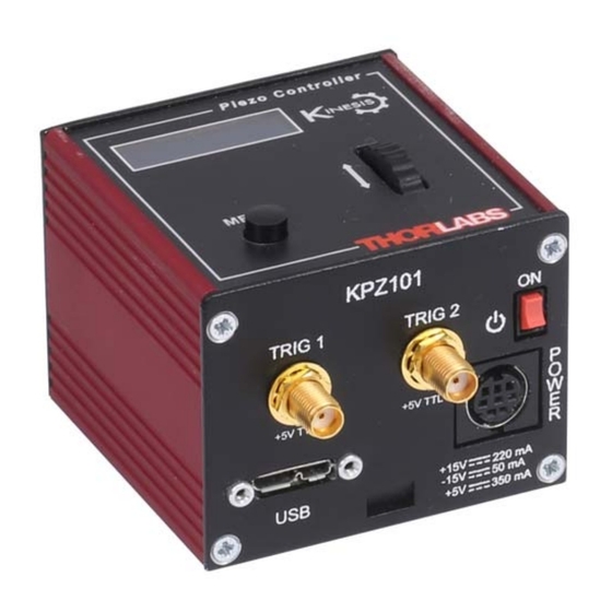
- Page 1 KPZ101 Piezo Driver Kinesis User Guide Original Instructions...
-
Page 2: Table Of Contents
Contents Chapter 1 Safety ..................... 4 1.1 Safety Information .................. 4 1.2 General Warnings .................. 4 Chapter 2 Overview and Setup ..............5 2.1 Introduction ..................... 5 2.2 Power Options ..................6 2.3 Kinesis PC Software Overview ............... 7 Chapter 3 Getting Started ................9 3.1 Install The Software. - Page 3 Appendix A Connector Pinout Details ............56 Appendix B Preventive Maintenance ............57 Appendix C Specifications and Associated Products ......58 Appendix D Piezo Operation - Background ..........60 Appendix E Regulatory ................63 Appendix F Thorlabs Worldwide Contacts ..........67...
-
Page 4: Chapter 1 Safety
Chapter 1 Safety 1.1 Safety Information For the continuing safety of the operators of this equipment, and the protection of the equipment itself, the operator should take note of the Warnings, Cautions and Notes throughout this handbook and, where visible, on the product itself. The following safety symbols may be used throughout the handbook and on the equipment itself. -
Page 5: Chapter 2 Overview And Setup
This driver is capable of delivering up to 150V of drive voltage at 7.5mA - allowing operating bandwidths up to 1kHz (see specs). The KPZ101 provides immediate 'out of the box' operation with the Thorlabs complete range of bare piezo stacks, piezo equipped actuators and piezo driven mirror mounts. -
Page 6: Power Options
2.2 Power Options For power, a compact two-way power supply unit (TPS002) is available from Thorlabs allowing up to 2 K-Cube Piezo Drivers to be powered from a single mains outlet. This power supply unit is also designed to take up minimal space and can be mounted to the optical table in close proximity to the driver units, connected via short power leads. -
Page 7: Kinesis Pc Software Overview
K-Cube Piezo Driver 2.3 Kinesis PC Software Overview 2.3.1 Introduction The K-Cube range of controllers share many of the benefits. These include USB connectivity (allowing multiple units to be used together on a single PC), fully featured Graphical User Interface (GUI) panels, and extensive software function libraries for custom application development. - Page 8 This is available either by pressing the F1 key when running the Kinesis server, or via the Start menu, Start\Programs\Thorlabs\Kinesis\Kinesis Help. 2.3.3 Software Upgrades Thorlabs operate a policy of continuous product development and may issue software upgrades as necessary. HA0365T Rev Dk Jan 2017...
-
Page 9: Chapter 3 Getting Started
If you experience any problems when installing software, contact Thorlabs on +44 (0)1353 654440 and ask for Technical Support. DO NOT CONNECT THE CONTROLLER TO YOUR PC YET 1) Go to Services/Downloads at www.thorlabs.com and download the software. -
Page 10: Mechanical Installation
(KCH301 and KCH601). ) are also available - see Section 2.2. for further details. Full instructions on the fitting and use of the controller hub are contained in the handbook available at www.thorlabs.com Cautions When siting the unit, it should be positioned so as not to impede the operation of the control panel buttons. -
Page 11: Electrical Installation
K-Cube Piezo Driver 3.2.3 Using the Baseplate The baseplate must be bolted to the worksurface before the K-Cube is fitted, as shown below. The K-cube is then located on two dowels in the baseplate and secured by two clips. Fig. 3.1 Using The Baseplate 3.3 Electrical Installation 3.3.1 Rear Panel Fig. - Page 12 EXT IN and MONITOR connectors is always 0 to +10V full scale. Note Thorlabs supply a variety of SMA to BNC and SMC to BNC adaptor and extension cables. Please see our catalog, or visit www.Thorlabs.com for further details.
- Page 13 K-Cube Piezo Driver 3.3.3 Front Panel Warning The unit must be connected only to a DC supply as detailed in Section 3.3. Connection to a supply of a different rating may cause damage to the unit and could result in injury to the operator. Caution Ensure the power switch on the front panel of the unit is switched off before connecting power to the K-Cube.
- Page 14 3) The Version number of the embedded software is displayed for a few seconds. Thorlabs offers a compact, two-way power supply unit (TPS002), allowing up to two piezo driver K-Cubes to be powered from a single mains outlet. However, if an external supply is to be used, see Appendix A.1 for power supply connector pin out...
-
Page 15: Connect The Hardware
K-Cube Piezo Driver 3.4 Connect The Hardware 1) Perform the mechanical installation as detailed in Section 3.2. 2) Install the Kinesis Software. Caution During items (3) to (6) the instructions should be followed strictly in the order stated. Problems may occur if the process is not performed in the correct sequence. -
Page 16: Chapter 4 Standalone Operation
Persons using the KPZ101 controller must understand the hazards associated with using high voltages and the steps necessary to avoid risk of electrical shock. If the KPZ101 is used in a manner not specified by Thorlabs, the protective features provided by the product may be impaired. -
Page 17: Control Panel
K-Cube Piezo Driver 4.2 Control Panel Piezo Controller MENU Fig. 4.1 Panel Controls and Indicators MOVE Controls - These controls allow all motor moves to be initiated. Velocity Wheel - Used to drive the motor at a varying speed in either forward or reverse directions for full and easy motor control - see Section 4.3.1. -
Page 18: Velocity Wheel Operation
Chapter 4 4.3 Velocity Wheel Operation The velocity wheel/joystick is an infinite turn potentiometer, which is used to initiate different types of move depending on its mode setting. The mode can be set either via the GUI Settings panel, see Section 6.2.3. or via the top panel display menu, see Section 4.4. -
Page 19: Settings Menu
K-Cube Piezo Driver 4.4 Settings Menu Before the settings menu can be accessed, the drive output must be enabled as follows.. T h o r l a b s K P Z 1 0 1 S w R e v 0 1 0 0 0 1 O u t p u t i n a c t i v e 7 5 V N V Press the MENU button... - Page 20 Chapter 4 4.4.1 Menu Overview V o l t a g e : 0 . 0 0 V 7 5 V N V Press the MENU button MENU M e n u o p t i o n s Use the wheel to scroll through the menu options U s e w h e e l Press the MENU button to enter a particular option M e n u o p t i o n s...
- Page 21 K-Cube Piezo Driver 4.4.2 Menu Option - HV output This mode is used to enable or disable the drive output. O u t p u t i n a c t i v e 7 5 V N V MENU Press the MENU button, then use the wheel to scroll through the menu options.
- Page 22 Thorlabs - see Section 5.3.1. for schematic diagrams of open and closed loop operation. This mode is used to set the feedback mode.
- Page 23 K-Cube Piezo Driver 4.4.5 Menu Option - Analogue input V o l t a g e : 0 . 0 0 V The K-Cube piezo driver has 3 external inputs whose 1 5 0 V N J function depends on whether the cube is used in open or MENU closed loop mode - see Section 4.4.6.
- Page 24 Chapter 4 4.4.6 External Inputs The K-Cube piezo driver has 3 external inputs whose function depends on whether the cube is used in open or closed loop mode. In open loop mode, the selected input drives the high voltage amplifier directly, whilst in closed loop mode the selected input receives the feedback position signal from the external position reader (such as the KSG101 Strain Gauge Reader).
- Page 25 K-Cube Piezo Driver 4.4.7 Menu Option - Joystick mode V o l t a g e : 0 . 0 0 V This mode is used to set the operating mode of the 1 5 0 V A J joystick wheel. MENU Press the MENU button, then use the wheel to scroll M e n u o p t i o n s...
- Page 26 Chapter 4 4.4.8 Menu Option - Joystick menu V o l t a g e : 0 . 0 0 V This mode is used to set various parameters depending 1 5 0 V A J on the Joystick mode setting - see Section 4.4.7. MENU Press the MENU button, then use the wheel to scroll M e n u o p t i o n s...
- Page 27 K-Cube Piezo Driver 4.4.9 Menu Option - Teach voltage This mode is used to set the teach positions, used when the Joystick mode option is set to Go to voltages mode - see Section 4.4.7. To set Teach Voltage 1... V o l t a g e : 3 5 .
- Page 28 Chapter 4 4.4.10 Menu Option - 8 Wheel lock In certain applications, it may be advantageous to disable the wheel to remove the possibility of unwanted motion due to accidental movement of the wheel. V o l t a g e : 3 5 . 3 0 V V o l t a g e : 3 5 .
- Page 29 K-Cube Piezo Driver 4.4.11 Menu Option - Brightness V o l t a g e : 3 5 . 3 0 V V o l t a g e : 3 5 . 3 0 V In certain applications, it may be necessary to adjust the 1 5 0 V A J 1 5 0 V A J brightness of the LED display.
-
Page 30: Chapter 5 Pc Operation - Tutorial
1) Power up the hardware, and wait until the KPZ101 has finished booting up, then run the Kinesis software - Start/All Programs/Thorlabs/Kinesis/Kinesis. Note For maximum accuracy, wait approximately 30 mins for the unit to thermally stabalize to the environment. -
Page 31: Introduction To Open And Closed Loop Operation
Closed loop operation is only possible if an external position signal is available to control the piezo cube. For the Thorlabs range of piezo actuators, the KSG101 strain gauge reader is a fully self contained unit that is designed to work with the KPZ101 in closed loop mode, providing the feedback signal necessary for closed loop operation. - Page 32 Chapter 5 The output voltage is controlled by the DSP, allowing the Kinesis server to set the output voltage. The output voltage can also be controlled by the top panel potentiometer. In addition, one of the 3 possible external inputs (SMA input, Hub Channel 1 or Hub Channel 2) can also be added to the signal that controls the output voltage.
-
Page 33: Open Loop Operation
K-Cube Piezo Driver 5.4 Open Loop Operation The following procedures explain how the piezo actuator is driven. In open loop mode, the piezo can be positioned in three ways: by entering a voltage, by using the ‘Output’ potentiometer or by clicking the ‘Jog’ buttons. 5.4.1 Entering the piezo voltage 1) Click the Set Arrow to display the Target window.. - Page 34 Chapter 5 5.4.3 Using the Controller as a Piezo Amplifier Certain applications may require the piezo to be driven by a voltage generated from an external source (e.g. a signal generator). The piezo K-Cube is designed to accept an external 0 to 10V signal and handle the amplification from 10V to 75 or 150V. As an example, the following procedure explains how to configure the unit as a piezo amplifier.
-
Page 35: Operation With Other Members Of The K-Cube Family
K-Cube Piezo Driver 5.5 Operation with Other Members of the K-Cube Family 5.5.1 Introduction The operation of the KPZ101 piezo controller can be extended when the unit is used in conjunction with other members of the K-Cube family. Specifically, 2 other controllers have been designed to work closely with the KPZ101 piezo unit;... - Page 36 Wait while Windows installs the drivers for the new hardware. 9) Run the Kinesis software - Start/All Programs/Thorlabs/Kinesis/Kinesis. 10) Click the ‘Settings’ button on GUI of the Piezo Driver to display the Settings panel (shown below).
- Page 37 K-Cube Piezo Driver Note To identify the piezo unit associated with the GUI panel, click the ‘Ident’ button; the Power LED and the Display of the asssociated controller flashes for a short period. Fig. 5.8 Piezo Driver Settings Note The following parameter settings are shown for example only, and are by no means the only possible setting combinations.
- Page 38 Chapter 5 If desired, click the ‘Persist Settings To Hardware’ box. These settings will then be loaded on each power up cycle. 12) Click ‘OK to save the settings. 13) Click the ‘Settings’ button on GUI of the Strain Gauge Reader fitted in bay 2, to display the Settings panel (shown below).
- Page 39 K-Cube Piezo Driver 5.6.2 Piezo Driver Hub Mounting Options. When the K-Cube piezo driver is used on the hub, together with the KSG101 strain gauge unit, signals can be routed via dedicated internal communication channels. These channels are selected via the piezo unit settings panel, or via the ‘MODE’ button on the top panel of the unit.
- Page 40 Chapter 5 all units set to Hub Channel 2 bay 1 bay 2 bay 3 bay 4 MODE MODE POSITION POSITION VOLTAGE VOLTAGE FORCE FORCE POWER POWER Hub Channel 1 Hub Channel 2 bay 2 bay 3 bay 5 bay 6 MODE MODE POSITION...
- Page 41 Communication lengths in excess of 3 metres can be achieved by using a powered USB hub). 8) Windows should detect the new hardware. Wait while Windows installs the drivers for the new hardware. 9) Run the Kinesis software - Start/All Programs/Thorlabs/Kinesis/Kinesis.
- Page 42 Chapter 5 10) Click the ‘Settings’ button on the GUI panel of the Piezo Driver to display the Settings panel (shown below). . Fig. 5.13 Piezo Driver Settings 11) Make the following parameter settings, as shown in Fig. 5.8 Control Tab Loop Mode - Select Closed Loop Maximum Voltage - Set the corresponding voltage for the piezo being driven, 75V, 100V or 150V.
- Page 43 K-Cube Piezo Driver 5.6.4 Entering the piezo percentage position 1) Click the Set Arrow to display the Target window.. Fig. 5.14 Target Position Popup Window 2) Enter a position as a percentage of total piezo travel. This can be entered directly into the field, or by clicking on the up/down arrows.
-
Page 44: Adjusting The Piezo Position
Chapter 5 5.7 Adjusting the Piezo Position Note The position of the actuator is relative to the minimum position set for the arrangement using the ‘Null’ facility, see Section 5.6.5. The extension of the actuator is displayed on the Strain Gauge K-Cube as a position in microns. -
Page 45: Load Response
K-Cube Piezo Driver 5.8 Load Response The response of the KPZ101 to varying load and frequencies is shown below. Fig. 5.15 Response of KPZ101 to Varying Loads and Frequencies 5.9 Setting Move Sequences The Kinesis software allows move sequences to be programmed, allowing several positions to be visited without user intervention. -
Page 46: Chapter 6 Software Reference
Chapter 6 Software Reference 6.1 GUI Panel The following screen shot shows the graphical user interface (GUI) displayed when accessing the controller using the Kinesis software. Fig. 6.1 KPZ101 Piezo Driver Software GUI Note The serial number of the KPZ101 unit associated with the GUI panel, is displayed in the top right hand corner. - Page 47 K-Cube Piezo Driver Parameters Display - shows the maximum working voltage of the associated piezo actuator and the present setting for the step size Settings - Displays the 'Settings' panel, which allows the operating parameters to be entered for the motor drive - see Section 6.2. Active - lit when the unit is operating normally and no error condition exists.
-
Page 48: Settings Panel
Chapter 6 6.2 Settings Panel When the 'Settings' button on the GUI panel is clicked, the 'Settings' window is displayed. This panel allows data such as jog step size and input sources to be entered. Note that all of these parameters have programmable equivalents accessible through the functions on this Control (refer to the Kinesis API helpfile for further details. - Page 49 When the K-Cube Piezo Driver is used in conjunction with the K-Cube Strain Gauge Reader unit (KSG101) on the K-Cube Controller Hub (TCH002), high precision closed loop operation is possible using the complete range of feedback equipped piezo actuators available from Thorlabs. Select Open Loop or Closed Loop as required. Note...
-
Page 50: Ha0365T Rev Dk Jan
This must be set up to suit the maximum specified operating voltage of the piezo actuator connected to the unit. Most Thorlabs piezo actuators are specified for either 75V or 150V maximum operation. In general, the maximum voltage should not be exceeded because it can cause damage to the piezo actuator. - Page 51 K-Cube Piezo Driver 6.2.3 Advanced Tab Drive Input Settings Analogue Input Mode - This field allows the user to select the analogue input source, which can be one of 3 inputs: If Analogue Channel 1 is selected, the feedback signal runs through all the bays - see Fig.
- Page 52 Chapter 6 used for closed loop control but in this case the KSG101 MONITOR output must be connected to the KPZ101 EXT IN input using an external SMA to SMA cable. Note As mentioned in the previous section, the function of the analogue input source depends on whether the cube is used in open or closed loop mode.
- Page 53 K-Cube Piezo Driver MMI Controls The voltage wheel/joystick is an infinite turn potentiometer, which is used to initiate different types of move depending on its mode setting. The mode can be set either via the GUI Settings panel as follows or via the top panel display menu, see Section 4.4.
- Page 54 Dim device display on inactivity box is checked. Triggering Introduction The K-Cube piezo controller has two bidirectional trigger ports (TRIG1 and TRIG2) that can be used to read an external logic signal or output a logic level to control external equipment.
- Page 55 K-Cube Piezo Driver moves. The trigger input has to return to its inactive state first in order to start the next trigger. The mode is set in the Trigger 1 Mode and Trigger 2 Mode parameters as follows: Disabled - The trigger IO is disabled Digital Input - General purpose logic input (read through status bits using the LLGetStatusBits method).
-
Page 56: Appendix A Connector Pinout Details
A.1 Power Connector A.1.1 Pin Identification Thorlabs recommends that the piezo cube is operated with Thorlabs power supply TPS002, as it was specifically designed for use with this product. However, to enable customers to use the cube in installations where a ±15V and 5V power is already available, the piezo cube can be operated with a different external power supply, such as a bench or lab supply. -
Page 57: Appendix B Preventive Maintenance
The equipment contains no user servicable parts. There is a risk of electrical shock if the equipment is operated with the covers removed. Only personnel authorized by Thorlabs Ltd and trained in the maintenance of this equipment should remove its covers or attempt any repairs or adjustments. Maintenance is limited to safety testing and cleaning as described in the following sections. -
Page 58: Appendix C Specifications And Associated Products
Appendix C Specifications and Associated Products C.1 Specifications Parameter Value Piezoelectric Output Piezo Drive Voltage 0 - 150V max. (SMC Connector) Piezo Drive Current 7.5mA max. continuous User Voltage Control Digital Potentiometer (Resolution Selectable) Output Noise No Load Condition: < 5mV rms With 3.6 µF Load: <... - Page 59 K-Cube Piezo Driver C.2 Associated Products Product Name Part Number Drive Cable for Piezoelectric Actuators (3.0 m) PAA100 Drive Cable Extension for Piezo Actuators (3.0 m) PAA100A Drive Cable for Piezoelectric Actuators (1.5 m) PAA101 Drive Cable Extension for Piezo Actuators (1.5 m) PAA101A K-Cube Strain Gauge Reader KSG101...
-
Page 60: Appendix D Piezo Operation - Background
– see Fig. D.1. In this way, the distance from positive to negative electrodes is very small. A large field gradient can therefore be obtained with a modest drive voltage (75 V in the case of most Thorlabs actuators). expansion piezoelectric... - Page 61 Some Thorlabs nanopositioning actuators have position sensing, others do not. The Piezoelectric control module allows both types to be controlled.
- Page 62 Appendix D moving open loop control part demand actuator moving closed loop control part demand a + b/s actuator sensor Fig. D.3 Open loop and closed loop control The result of using closed-loop control is a linear relationship between demand (voltage) and measured position –...
-
Page 63: Appendix E Regulatory
Appendix E Regulatory E.1 Declarations Of Conformity E.1.1 For Customers in Europe See Section E.3. E.1.2 For Customers In The USA This equipment has been tested and found to comply with the limits for a Class A digital device, persuant to part 15 of the FCC rules. These limits are designed to provide reasonable protection against harmful interference when the equipment is operated in a commercial environment. - Page 64 • left over parts of units disassembled by the user (PCB's, housings etc.). If you wish to return a unit for waste recovery, please contact Thorlabs or your nearest dealer for further information. E.2.2 Waste treatment on your own responsibility If you do not return an "end of life"...
- Page 65 K-Cube Piezo Driver E.3 CE Certificate...
- Page 66 Appendix E HA0365T Rev Dk Jan 2017...
-
Page 67: Appendix F Thorlabs Worldwide Contacts
Fax: 973-300-3600 Fax: +46-31-703-40-45 www.thorlabs.com www.thorlabs.de email: scandinavia@thorlabs.com www.thorlabs.us (West Coast) email: feedback@thorlabs.com Brazil Support: techsupport@thorlabs.com Thorlabs Vendas de Fotônicos Ltda. Rua Riachuelo, 171 Europe São Carlos, SP 13560-110 Thorlabs GmbH Brazil Hans-Böckler-Str. 6 Tel: +55-16-3413 7062 85221 Dachau Fax: +55-16-3413 7064 Germany www.thorlabs.com... - Page 68 Thorlabs Inc. Thorlabs Ltd. 56 Sparta Ave Saint Thomas Place, Ely Newton, NJ07860 Cambridgeshire CB7 4EX, Tel: +1 973 579 7227 Tel: +44 (0) 1353 654440 Fax: +1 973 300 3600 Fax: +44 (0) 1353 654444 www.thorlabs.com www.thorlabs.com...
Need help?
Do you have a question about the K-Cube Piezo Controller and is the answer not in the manual?
Questions and answers