Table of Contents
Advertisement
Quick Links
Advertisement
Table of Contents

Related Manuals for THORLABS KST101


Summary of Contents for THORLABS KST101
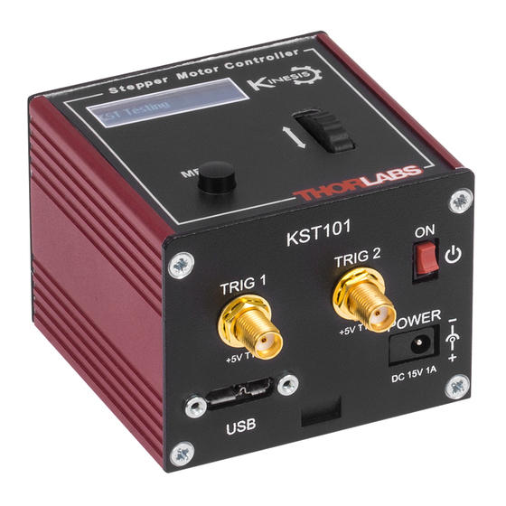
- Page 1 KST101 K-Cube Stepper Motor Controller Kinesis User Guide Original Instructions...
-
Page 2: Table Of Contents
Contents Chapter 1 Safety ..................... 4 1.1 Safety Information .................. 4 1.2 General Warnings .................. 4 Chapter 2 Overview and Setup ..............5 2.1 Introduction ..................... 5 2.2 K-Cube Controller Hub ................6 2.3 Kinesis PC Software Overview ............... 7 2.3.1 Introduction ...................... - Page 3 Appendix A Rear Panel Connector Pinout Details ........53 Appendix B Preventive Maintenance ............54 Appendix C Specifications ................55 Appendix D Stepper Motor Operation - Background ........ 57 Appendix E Regulatory ................63 Appendix F Thorlabs Worldwide Contacts ..........66...
-
Page 4: Chapter 1 Safety
Chapter 1 Safety 1.1 Safety Information For the continuing safety of the operators of this equipment, and the protection of the equipment itself, the operator should take note of the Warnings, Cautions and Notes throughout this handbook and, where visible, on the product itself. The following safety symbo ls may be u sed throughout the h andbook and on the equipment itself. -
Page 5: Chapter 2 Overview And Setup
DSP controll er that provides a un ique high resolution microstepping capability for such a compact unit. The KST101 is optimised for 'out of the box' operation with the Thorlabs range of ZST stepper motor actuators, however its highly flexible parameter set also supports operation a wid e range of stepper motors and associated stages/actuators. -
Page 6: K-Cube Controller Hub
For power, a single way wall plug supply (KPS101) is available for powering a single K-Cube Driver. As a further level of convenience when using the new K-Cube Controllers Thorlabs also offers th e 3-channel and 6 -channel K-Cube Controller Hubs (KCH301 and KCH601). -
Page 7: Kinesis Pc Software Overview
2.3 Kinesis PC Software Overview 2.3.1 Introduction The K-Cube range of controllers share many of the benefits of the Thorlabs range of motor controllers. These include USB connectivity (allowing multiple units to be used together on a single PC), fully featured Graphical User Interface (GUI) panels, and extensive software function libraries for custom application development. -
Page 8: Kinesis Server
Chapter 2 2.3.2 Kinesis Server Kinesis controls are re-usable compiled software components that supply both a graphical user interface and a pro grammable interface. Many such Co ntrols are available for Windows applications development, providing a large range of re-usable functionality. -
Page 9: Software Upgrades
Ki nesis Controls collection. This is available either by pressing the F1 key when running the Kinesis server, or via the Start menu, Start\Programs\Thorlabs\Kinesis\Kinesis Help. 2.3.3 Software Upgrades Thorlabs operate a policy of continuous product development and may issue software upgrades as necessary. -
Page 10: Chapter 3 Getting Started
If you experience any problems when installing software, contact Thorlabs on +44 (0)1353 654440 and ask for Technical Support. DO NOT CONNECT THE CONTROLLER TO YOUR PC YET 1) Download the software from www.thorlabs.com. -
Page 11: Mechanical Installation
(KCH301 and KCH601). ) are also available - see Section 2.2. for further details. Full instructions on the fitting and use of the controller hub are contained in the handbook available at www.thorlabs.com. Caution When siting the unit, it should be positioned so as not to impede the operation of the control panel buttons. -
Page 12: Using The Baseplate
Fig. 3.2 Rear Panel Connections The rear panel of the unit is fitted with a 15 pin D-type connector as shown above, which is compatible with all new Thorlabs DC servo motor a ctuators (refer to Appendix A for details of pin outs). -
Page 13: Front Panel
POWER - A Standard 3.5 mm front panel jack connector for connecting the unit to a regulated DC power supply of 15 V, 1A. Thorlabs offers a compact, multi-way power supply unit (TPS008), allowing up to eight Driver K-Cubes to be powered from a single mains outlet. A single way wall plug supply (KPS101) for powering a single Driver K-Cube is also available. -
Page 14: Connect The Hardware
Z F S 2 5 A t + 0 . 0 0 0 0 m m S t o p p e d Fig. 3.4 KST101 start up screens 8) Windows should detect the new hardware. Wait while Windows installs the drivers for the new hardware. -
Page 15: Use With Legacy Actuators And Stages
K-Cube Stepper Motor Controller 3.5 Use with Legacy Actuators and Stages To ensure that a particular stage is driven properly by the system, a number of parameters must first be set. These parameters relate to the physical characteristics of the stage be ing driven (e.g. min and max positions, leadscrew pitch, homing direction etc.). -
Page 16: Verifying Software Operation
Chapter 3 3.6 Verifying Software Operation 3.6.1 Initial Setup 1) Run the Kinesis software and check that the Graphical User Interface (GUI) panel appears and is active. Fig. 3.5 Gui panel showing jog and ident buttons 2) Check that the actuator type is displayed in the GUI panel. 3) Click the ‘Identify’... -
Page 17: Chapter 4 Standalone Operation
The Stepper Driver K-Cube has be en designed specifically to operate with low er power stepper motors such as the Thorlabs ZST series, however it can also drive a variety of other ste pper motors (15V operation) equipped with or without encoder feedback. -
Page 18: Digital Display - Operating Mode
Chapter 4 Digital Display - The display shows the menu options and settings, accessed via the menu button - see Section 4.4. When the Ident button on the associated GUI panel is clicked, the display will flash for a short period. MENU - used to access the settings menu - see Section 4.4. -
Page 19: Velocity Wheel Operation
K-Cube Stepper Motor Controller is moved up. T hese ‘taught’ positions can be set through the software GUI - see Section 6.3.5. or via the display menu, see Section 4.4.7. This mode of operation is enabled by setting the ‘Wheel Mode’ to ‘Go To Position’ through the software GUI - see Section 6.3.5. -
Page 20: Settings Menu
Chapter 4 4.4 Settings Menu 4.4.1 Overview A t 0 . 0 0 0 0 m m S t o p p e d Press the MENU button MENU Use the wheel to scroll through the menu options M e n u o p t i o n s U s e w h e e l Press the MENU button to enter a particular option M e n u o p t i o n s... -
Page 21: Menu Option - Go To Position
K-Cube Stepper Motor Controller 4.4.2 Menu Option - Go to position This mode is used to move to an absolute position. A t 0 . 0 0 0 0 m m S t o p p e d MENU Press the MENU bu tton, then use the wheel to scroll through the menu options. -
Page 22: Menu Option - Start Homing
Chapter 4 4.4.3 Menu Option - Start homing A t 2 . 0 0 0 0 m m This mode is used to home the stage. S t o p p e d MENU Press the MENU bu tton, then use the wheel to scroll through the menu options. -
Page 23: Menu Option - Joystick Mode
K-Cube Stepper Motor Controller 4.4.5 Menu Option - Joystick Mode This mode i s used to set the operating mode of the A t 0 . 0 0 0 0 m m joystick wheel. H o m e d S t o p p e d V MENU Press the MENU bu tton, then use the wheel to scroll M e n u o p t i o n s... -
Page 24: Menu Option - Jog Step Size
Chapter 4 4.4.6 Menu Option - Jog Step Size This mode is used to set the jog step size. A t 0 . 0 0 0 0 m m H o m e d S t o p p e d V MENU Press the MENU bu tton, then use the wheel to scroll M e n u o p t i o n s... -
Page 25: Menu Option - Teach Position
K-Cube Stepper Motor Controller 4.4.7 Menu Option - Teach Position This mode is used to set the teach positions, used when the Joystick mode option is set to Jog to positions mode - see Section 4.4.5. To set Teach Position 1... A t 1 0 . -
Page 26: Menu Option - Brightness
Chapter 4 4.4.8 Menu Option - Brightness A t 0 . 0 0 0 0 m m In certain applications, it may be necessary to adjust the H o m e d S t o p p e d V brightness of the LED display. - Page 27 K-Cube Stepper Motor Controller 4.4.10 Menu Option - Disable In certain applications, it may be advantageous to disable A t 0 . 0 0 0 0 m m the wheel to remove the possibility of unwanted motion H o m e d S t o p p e d V due to accidental movement of the wheel.
-
Page 28: Menu Option - Select Stage
Chapter 4 4.4.11 Menu Option - Select stage Note Later version actuators and stages have an identification eprom fitted such that the system will recognise automatically the actuator type and install suitable defaults at start up. In this case, the start up screens will show ‘Stage connected xxx’... -
Page 29: Chapter 5 Pc Operation - Tutorial
1) If required, perform the stage association as detailed in Section 4.4.11. 2) Run the Kinesis software - Start/All Programs/Thorlabs/Kinesis/Kinesis. 3) Notice how the actuator type i s displayed in the wi ndow. See Section 6. and Section 6.3. -
Page 30: Homing Motors
Chapter 5 5.3 Homing Motors Homing the motor moves the actuator to the home limit switch and resets the internal position counter to zero. The limit switch provides a fixed datum that can be found after the system has been powered up. Fig. -
Page 31: Changing Motor Parameters And Moving To An Absolute Position
K-Cube Stepper Motor Controller 5.4 Changing Motor Parameters and Moving to an Absolute Position Absolute moves are measured in real world units (e.g. millimetres), relative to the Home position. Moves are performed using a trapezoidal velocity profile (see Appendix D , Section D.1.3.). -
Page 32: Jogging
Chapter 5 5.5 Jogging During PC operation, the motor actuators are jogged using the GUI panel arrow keys. There are two jogging modes available, ‘Single Step’ and ‘Continuous’. In ‘Single Step’ mode, the motor moves by the ste p size specifie d in the Ste p Distance parameter. -
Page 33: Setting Move Sequences
K-Cube Stepper Motor Controller 5.6 Setting Move Sequences The Kinesis software allows move seque nces to be programmed, allowing several positions to be visited without user intervention. For more details and instructions on setting move sequences, please see the Kinesis Helpfile. 5.7 Changing and Saving Parameter Settings During operation, certain setting s (e.g. -
Page 34: Chapter 6 Software Reference
Chapter 6 Software Reference 6.1 Introduction This chapter gives an explanation of the parameters and settings accessed from the Kinesis software running on a PC. 6.2 GUI Panel The following screen shot shows the graphical user interface (GUI) d isplayed when accessing the Stepper Driver K-Cube using the Kinesis software. - Page 35 K-Cube Stepper Motor Controller These settings can be adjusted as described previously, or by clicking the Settings button to display the settings window, see Section 6.3.2. Jog Controls - used to increment or decrement the motor position. The controls comprise a bar graph and a set of j o g arrows.
-
Page 36: Keyboard Shortcuts
Chapter 6 Stop - halts the movement of the motor. Lower Display - Shows the present state of the motor, e.g. Idle, Moving, Moving EXT or Homing. Also shows the part number of the associated actuator or stage. 6.2.1 Keyboard Shortcuts Certain functionality can also be accessed via PC keyboard shortcuts as follows: Jog Forwards ‘Ctrl’... -
Page 37: Settings Panel
K-Cube Stepper Motor Controller 6.3 Settings Panel When the 'Settings' button on th e GUI pan el is clicked, the 'Settings' window is displayed. This panel allows motor operation parameters such as move/jog velocities, and stage/axis information to be modified. Note that all of th ese parameters have programmable equivalents (refer to the Kinesis Server helpfile for further details. -
Page 38: Moves/Jogs Tab
Chapter 6 6.3.2 Moves/Jogs Tab Fig. 6.2 Stepper Driver K-Cube - Move/Jog Settings Display Units By default, the unit will display position in real world units (mm or degrees). If required, the units can be changed to so that the display shows other positional units (cm, µm, µrad etc). - Page 39 K-Cube Stepper Motor Controller In ‘Continuous’ mode, the motor actuator will accelerate and move at the jog velocity while the button is held down.. Fig. 6.3 Jog Modes Jog - the motor moves by the distance specified in the Step Size parameter. Continuous - the motor continues to move until the jog signal is removed (i.e.
- Page 40 Chapter 6 Backlash Distance - The system compensates for lead scr ew backlash during reverse direction moves, by moving passed the demanded position by a sp ecified amount, and then reversing. This ensures that positions are always approached in a forward direction. The Backlash Distance is speci fied in rea l world units (millimeters or degrees).
- Page 41 K-Cube Stepper Motor Controller motion profile. The Bow Value is applied in mm/s and is derived from the Bow Index field as follows: (Bow Index -1) Bow Value = 2 within the range 1 to 262144 (Bow Index 1 to 18). In this profile mode , the acceleration increases gradually from 0 to the specified acceleration value, then decreases at the same rate until it reaches 0 again at the specified velocity.
-
Page 42: Calibration Tab
Chapter 6 6.3.3 Calibration Tab Note Currently, Thorlabs do not supply calibration files for any stages or actuators compatible with the KST101 Stepper Motor Controller. The following information is supplied to allow calibration data compiled by the customer to be uploaded. -
Page 43: Stage/Axis Tab
They need to be set accordingly such that a particular stage is driven properly by the system. For Thorlabs stages, the stage being driven must be associated with the driver, see Section 4.4.11. Once this association has been made, the Kinesis... - Page 44 Chapter 6 Homing Settings When homing, a stage typically moves in the reverse direction, (i.e. towards the reverse limit switch). The following settings allow support for stages with both Forward and Reverse limits. Note Typically, the following two parameters are set the same, i.e. both Forward or both Reverse.
-
Page 45: Advanced Tab
K-Cube Stepper Motor Controller 6.3.5 Advanced Tab Fig. 6.8 Stepper Driver K-Cube - Advanced Settings MMI Controls The velocity wheel is sprung such that when released it returns to it’s central position. In this central position the motor is stationary. As the wheel is moved away from the center, the motor begins to move;... - Page 46 Chapter 6 Joystick Direction The direction of a move initiated by the velocity wheel is specified as follows: Forwards - Upwards rotation of the wheel results in a positive motion (i.e. increased position count). Note. The following option applies only when the Wheel Mode is set to Velocity Control.
-
Page 47: Triggering Tab
K-Cube Stepper Motor Controller The Resting Power is entered as a percentage of full power. Note The default values applied by the software have been selected based on the type of stage or actuator associated with the motor drive. Modify these values with caution (particularly the rest power) as the risk of damage to the motor due to overheating is significant. - Page 48 Chapter 6 Triggering Introduction The K-Cube motor controllers have two bidirectional trigger ports (TRIG1 and TRIG2) that can be used to read an external logic signal or output a logic level to control external equipment. Either of them can be independently configured as an input or an output and the active logic state can be selected High or Low to suit the requirements of the application.
- Page 49 K-Cube Stepper Motor Controller Output Trigger Modes When the Trigger 1 Mode and Trigger 2 Mode parameters are configured as outputs, the TRIG ports can be used as a general purpose digital output, or to indicate motion status or to produce a trigger pulse at configurable positions as follows: OUT GPO - General purpose logic output.
- Page 50 Chapter 6 Trigger Out Position Steps Note If the trigger mode is not set to one of the three position step modes mentioned previously, then the following parameters are not applicable and will be hidden. As soon as a position triggering mode is selected on either of the TRIG ports, the port will assert the inactive logic state, set in the Trigger Polarity parameters.
- Page 51 parameter. This means that the total number of pulses output will be Trigger Cycle Counts x (Forward Trigger Count + Reverse Trigger Count).. PosIntervalFwd 15 mm Pos2 Fwd 12 mm Pos1 Rev StartPosRev 10 mm StartPosFwd Pos1 Fwd Time Trig Voltage Time Fig.
-
Page 52: Rotation Stagestab
Chapter 6 6.3.7 Rotation StagesTab Rotation Mode This setting relates to the way in which the angular position is displayed on the GUI panel. There are three options: Fixed Range - The angular rotation is limited to 360° i.e. one revolution. Equivalent Angle –... -
Page 53: Appendix A Rear Panel Connector Pinout Details
For Future Use For Future Use Caution DO NOT connect a motor actuator while the K-Cube is powered up. Only use motor drive cables supplied by Thorlabs, other cables may have incompatible wiring. Fig. A.1 MOTOR I/O Connector Pin Identification... -
Page 54: Appendix B Preventive Maintenance
Note The equipment contains no user servicable parts. Only personnel authorized by Thorlabs Ltd and trained in the maintenance of this equipment should remove its covers or attempt any repairs or adjustments. Maintenance is limited to safety testing and cleaning as described in the following sections. -
Page 55: Appendix C Specifications
Appendix C Specifications C.1 Specifications Parameter Value Motor Output Motor Drive Voltage 12-15 V (Depending on Supply) Motor Drive Current 750 m A (peak) Motor Drive Type 12-bit PWM Control Control Algorithm Open Loop Microstepping High Resolution Stepping 2048 Microsteps per Full Step 49,152 Microsteps per Revolution (24 Step Motor)( 409600 Microsteps per Revolution (200 Step Motor) Position Feedback... - Page 56 Appendix C Recommended Motor Requirements Peak Powers 15 W Step Angle Range 20° to 1.8° Rated Phase Current up to 1 A Peak Motor Mode Current Coil Resistance (nominal) 5 to 20 Ω Coil Inductance (nominal) 2 to 5.5 mH Phases Position Control Open Loop...
-
Page 57: Appendix D Stepper Motor Operation - Background
The size of the microstep depends on the resolution of the driver electronics. When used with the Thorlabs Stepper Driver K-Cube,128 microsteps per full step can be achieved, giving a total resolution of 3072 microsteps per revolution for a 24 full step motor. - Page 58 Appendix D orientation of the magnetic field generated by the stator and the orientation in which the rotor shaft comes to rest. D.1.2 Positive and Negative Moves Positive and negative are used to describe the direction of a move. A positive move means a move from a smaller absolute position to a larger one, a negative move means the opposite.
- Page 59 K-Cube Stepper Motor Controller The S-curve profile is a trapezoidal curve with an additional 'Bow Value' parameter, which limits the rate of change of acceleration and smooths out the contours of the motion profile. The Bow Value is specified in mm/s and is derived from the Bow Index field as follows: The Bow Value is applied in mm/s...
- Page 60 Appendix D D.2 Positioning a Stage D.2.1 General Whenever a command is re ceived to move a stage, the movement is sp ecified in motion units, (e.g. mil limetres). This motion unit valu e is conve rted to microstep s before it is sent to the stage by the Kinesis software.
- Page 61 K-Cube Stepper Motor Controller Home position can be found. Movement is allowed right through the switch position in either direction. Datum switch +ve limit switch -ve limit switch (or stop) Linear stage Rotary stage Fig. D.4 Stage limit switches D.2.4 Minimum and Maximum Positions These positions are dependent upon the stage or actuator to which the motors are fitted, and are defined as the minimum and maximum useful positions of the stage relative to the ‘Home’...
- Page 62 Appendix D D.2.5 Power Saving The current needed to hold a motor in a fixed position is much smaller than the current needed to move it. When a stepper motor is at rest it is advisable to reduce the phase (holding) currents so that the motor does not overheat.
-
Page 63: Appendix E Regulatory
Appendix E Regulatory E.1 Declarations Of Conformity E.1.1 For Customers in Europe See Section E.3. E.1.2 For Customers In The USA This equipment has be en tested an d found to comply with the limits fo r a Class A digital device, persua nt to part 15 of the FCC rules. - Page 64 • left over parts of units disassembled by the user (PCB's, housings etc.). If you wish to return a unit for waste recovery, please contact Thorlabs or your nearest dealer for further information. E.2.2 Waste treatment on your own responsibility If you do not return an "end of life"...
- Page 65 K-Cube Stepper Motor Controller E.3 CE Certificate...
-
Page 66: Appendix F Thorlabs Worldwide Contacts
Thorlabs Worldwide Contacts Appendix F For technical support or sales inquiries, please visit us at www.thorlabs.com/contact for our most up-to-date contact information. USA, Canada, and South America UK and Ireland Thorlabs, Inc. Thorlabs Ltd. sales@thorlabs.com sales.uk@thorlabs.com techsupport@thorlabs.com techsupport.uk@thorlabs.com Europe Scandinavia...
Need help?
Do you have a question about the KST101 and is the answer not in the manual?
Questions and answers