Table of Contents
Advertisement
Advertisement
Table of Contents

Related Manuals for THORLABS K-Cube Piezo Controller


Summary of Contents for THORLABS K-Cube Piezo Controller
- Page 1 KPZ101 Piezo Driver APT User Guide Original Instructions...
-
Page 2: Table Of Contents
Contents Chapter 1 Safety ..................... 4 1.1 Safety Information .................. 4 1.2 General Warnings .................. 4 Chapter 2 Overview and Setup ..............5 2.1 Introduction ..................... 5 2.2 K-Cube Controller Hub ................6 2.3 APT PC Software Overview ..............7 2.3.1 Introduction ...................... - Page 3 Appendix B Preventive Maintenance ............65 Appendix C Specifications and Associated Products ......66 Appendix D Piezo Control Method Summary ..........68 Appendix E Piezo Operation - Background ..........71 Appendix F Regulatory ................74 Appendix G Thorlabs Worldwide Contacts ..........77...
-
Page 4: Chapter 1 Safety
Chapter 1 Safety 1.1 Safety Information For the continuing safety of the operators of this equipment, and the protection of the equipment itself, the operator should take note of the Warnings, Cautions and Notes throughout this handbook and, where visible, on the product itself. The following safety symbo ls may be u sed throughout the h andbook and on the equipment itself. -
Page 5: Chapter 2 Overview And Setup
7.5mA - all owing operating bandwidths up to 1kHz (see specs). The KPZ101 provides immediate 'out of the box' operation with the Thorlabs complete range of bare piezo stacks, piezo equipped actuators and piezo driven mirror mounts. Furthermore, when operated together with the K-Cube Strain Gauge Reader unit (KSG101), high precision closed loop operation is possible using the complete range of feedback equipped piezo actuators available from Thorlabs. -
Page 6: K-Cube Controller Hub
2.2 Power Options For power, a compact two-way power supply unit (TPS002) is available from Thorlabs allowing up to 2 K-Cube Piezo Drivers to be powered from a single mains outlet. This power supply unit is also designed to take up minimal space and can be mounted to the optical table in close proximity to the driver units, connected via short power leads. -
Page 7: Apt Pc Software Overview
K-Cube Piezo Driver 2.3 APT PC Software Overview 2.3.1 Introduction As a member o f the APT ra nge of controllers, the KPZ101 piezo controller shares many of the associated software benefits. This includes USB connectivity (allowing multiple units to be used together on a single PC), fully featured Graphical User Interface (GUI) panels, and extensive software f unction libraries for custom application development. -
Page 8: Aptuser Utility
Chapter 2 2.3.2 APTUser Utility The APTUser application allows the user to interact with a number of APT hardware control units connected to the ho st PC. This program displays multiple graphical instrument panels to allow multiple APT units to be controlled from the same screen.. All basic operating parameters can be altered and, similarly, all operations (such as piezo moves) can be initiated. -
Page 9: Apt Config Utility
K-Cube Piezo Driver 2.3.3 APT Config Utility There are many system par ameters and co nfiguration settings associated with the operation of the APT Server. Most can be directly accessed using the various graphical panels, however there are several system wide settings that can only be made 'off-line' before running the APT software. -
Page 10: Apt Server (Activex Controls)
Chapter 2 2.3.4 APT Server (ActiveX Controls) ActiveX Controls are re -usable compiled software components that supp ly both a graphical user interface and a pro grammable interface. Many such Co ntrols are available for Windows applications development, providing a large range of re-usable functionality. -
Page 11: Software Upgrades
APT ActiveX Controls collection. This is available either by pressing the F1 key when running the APT server, or via the Start men u, Start\Programs\Thorlabs\APT\APT Help. 2.3.5 Software Upgrades Thorlabs operate a policy of continuous product development and may issue software upgrades as necessary. -
Page 12: Chapter 3 Getting Started
Thorlabs on +44 (0)1353 654440 and ask for Technical Support. DO NOT CONNECT THE CONTROLLER TO YOUR PC YET 1) Go to Services/Downloads at www.thorlabs.com and download the APT software. 2) Run the .exe file and follow the on-screen instructions. -
Page 13: Mechanical Installation
(KCH301 and KCH601). ) are also available - see Section 2.2. for further details. Full instructions on the fitting and use of the controller hub are contained in the handbook available at www.thorlabs.com Cautions When siting the unit, it should be positioned so as not to impede the operation of the control panel buttons. -
Page 14: Electrical Installation
Chapter 3 3.2.3 Using the Baseplate The baseplate must be bolted to the worksurface before the K-Cube is fitted, as shown below. The K-cube is then located on two dowels in the baseplate and secured by two clips. Fig. 3.1 Using The Baseplate 3.3 Electrical Installation 3.3.1 Rear Panel Fig. - Page 15 EXT IN and MONITOR connectors is always 0 to +10V full scale. Note Thorlabs supply a variety of SMA to BNC and SMC to BNC adaptor and extension cables. Please see our catalog, or visit www.Thorlabs.com for further details.
- Page 16 Chapter 3 3.3.3 Front Panel Warning The unit must be connected only to a DC supply as detailed in Section 3.3. Connection to a supply of a different rating may cause damage to the unit and could result in injury to the operator. Caution Ensure the power switch on the front panel of the unit is switched off before connecting power to the K-Cube.
- Page 17 3) The Version number of the embedded software is displayed for a few seconds. Thorlabs offers a com pact, two-way power supply unit (TPS002), allowing up to two piezo driver K-Cu bes to b e powered from a single mains outlet. However, if an external supply is to be used, see Appendix A.1 for power supply connector pin out...
-
Page 18: Connect The Hardware
Chapter 3 3.4 Connect The Hardware 1) Perform the mechanical installation as detailed in Section 3.2. 2) Install the APT Software. Caution During items (3) to (6) the instructions should be followed strictly in the order stated. Problems may occur if the process is not performed in the correct sequence. -
Page 19: Verifying Software Operation
K-Cube Piezo Driver 3.5 Verifying Software Operation The APT Software should be installed (Section 3.1.) and the controller connected to the actuators (see Section 3.4.) and the PC, before verifying software operation. Caution In applications requiring the highest level of accuracy and repeatability, it is recommended that the controller unit is powered up approximately 30 minutes before use, in order to allow the internal temperature to stabilize. - Page 20 Chapter 3 Follow the tutorial described in Chapter 5 for further guidance on basic operation. Note The 'APT Config' utility can be used to set up simulated hardware configurations and place the APT Server into simulator mode. In this way it is possible to create any number and type of simulated (virtual) hardware units in order to emulate a set of real hardware.
-
Page 21: Chapter 4 Standalone Operation
Persons using the KPZ101 controller must understand the hazards associated with using high voltages and the steps necessary to avoid risk of electrical shock. If the KPZ101 is used in a manner not specified by Thorlabs, the protective features provided by the product may be impaired. -
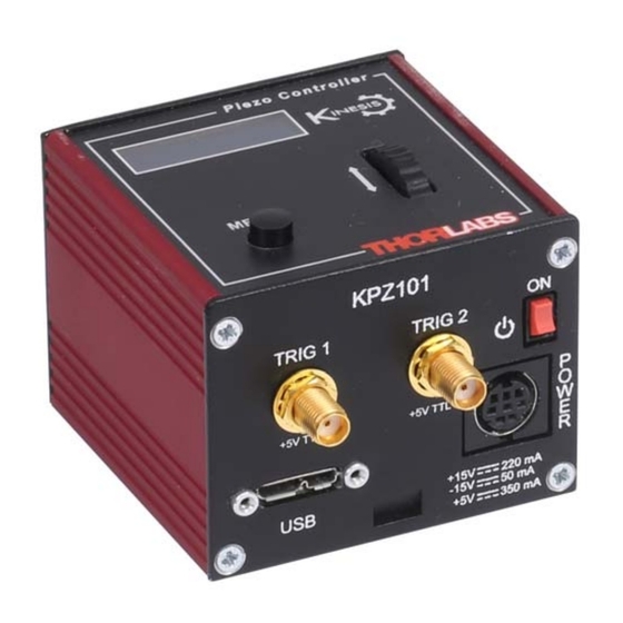
Page 22: Control Panel
Chapter 4 4.2 Control Panel Piezo Controller MENU Fig. 4.1 Panel Controls and Indicators MOVE Controls Velocity Wheel - Used to drive adjust the drive voltage when operating in Voltage Adjust mode - see Section 4.3.1. Also used to step through the settings menu. Digital Display - The display shows the operating data, menu options and settings, accessed via the menu button - see Section 4.4. -
Page 23: Velocity Wheel Operation
K-Cube Piezo Driver 4.3 Velocity Wheel Operation The velocity wheel/joystick is an infinite turn potentiometer, which is used to ini tiate different types of move depending on its mode setting. The mode can be set either via the GUI Settings panel, see Section 6.2.2. or via the top panel display menu, see Section 4.4. -
Page 24: Settings Menu
Chapter 4 4.4 Settings Menu Before the settings menu can be accessed, the drive output must be enabled as follows.. T h o r l a b s K P Z 1 0 1 S w R e v 0 1 0 0 0 1 O u t p u t i n a c t i v e 7 5 V N V Press the MENU button... - Page 25 K-Cube Piezo Driver 4.4.1 Menu Overview V o l t a g e : 0 . 0 0 V 7 5 V N V Press the MENU button MENU Use the wheel to scroll through the menu options M e n u o p t i o n s U s e w h e e l Press the MENU button to enter a particular option M e n u o p t i o n s...
-
Page 26: Ha0365T Rev D Jan
Chapter 4 4.4.2 Menu Option - HV output This mode is used to enable or disable the drive output. O u t p u t i n a c t i v e 7 5 V N V Press the MENU bu tton, then use the wheel to scroll MENU through the menu options. - Page 27 K-Cube Piezo Driver 4.4.4 Menu Option - Feedback mode V o l t a g e : 0 . 0 0 V When the K-Cube Piezo Driver is used in conjunction with 1 5 0 V N V the K-Cube Strain Gauge Reader unit (KSG101), high MENU precision closed loop operation is po ssible using the complete range of feedback equipped piezo actuators...
- Page 28 Chapter 4 4.4.5 Menu Option - Analogue input V o l t a g e : 0 . 0 0 V The K-Cube piezo driver has 3 external inputs whose 1 5 0 V N J function depends on whether the cube is used in open or MENU closed loop mode - see Section 4.4.6.
- Page 29 K-Cube Piezo Driver 4.4.6 External Inputs The K-Cube piezo driver has 3 external inputs whose function depends on whether the cube is used in open or closed loop mode. In open loop mode, the selected input drives the high voltage amplifier directly, whilst in closed loop mode the selected input receives the feedback position signal from the external position reader (such as the KSG101 Strain Gauge Reader).
- Page 30 Chapter 4 4.4.7 Menu Option - Joystick mode This mode is used to set the operating mode of the V o l t a g e : 0 . 0 0 V joystick wheel. 1 5 0 V A J MENU Press the MENU bu tton, then use the wheel to scroll M e n u o p t i o n s...
- Page 31 K-Cube Piezo Driver 4.4.8 Menu Option - Joystick menu V o l t a g e : 0 . 0 0 V This mode is used to set various parameters depending 1 5 0 V A J on the Joystick mode setting - see Section 4.4.7. MENU Press the MENU bu tton, then use the wheel to scroll M e n u o p t i o n s...
- Page 32 Chapter 4 4.4.9 Menu Option - Teach voltage This mode is used to set the teach positions, used when the Joystick mode option is set to Go to voltages mode - see Section 4.4.7. To set Teach Voltage 1... V o l t a g e : 3 5 . 3 0 V Using the me thod described in Section 4.4.7.
- Page 33 K-Cube Piezo Driver 4.4.10 Menu Option - 8 Wheel lock In certain applications, it may be adva ntageous to disable the wheel to remove the possibility of unwanted motion due to accidental movement of the wheel. V o l t a g e : 3 5 . 3 0 V V o l t a g e : 3 5 .
- Page 34 Chapter 4 4.4.11 Menu Option - Brightness V o l t a g e : 3 5 . 3 0 V V o l t a g e : 3 5 . 3 0 V In certain applications, it may be necessary to adjust the 1 5 0 V A J 1 5 0 V A J brightness of the LED display.
-
Page 35: Chapter 5 Operation - Tutorial
This tutorial shows how the APT User application provides all of the functionality necessary to operate the APT hardware. 1) Run the APT User prog ram - Start/All Programs/Thorlabs/APT User/APT User. The APT server registers automatically the units connected on the USB bus and... - Page 36 Chapter 5 Fig. 5.1 Typical APT User Screen Notice how the maximum voltage for the associated piezo is displayed in the ‘Voltage Range’ window . Fig. 5.2 Piezo Controller Software GUI HA0365T Rev D Jan 2017...
-
Page 37: Introduction To Open And Closed Loop Operation
Closed loop operation is only possible if an external position signal is avai lable to control the piezo cube. For the Thorlabs range of piezo actuators, the KSG101 strain gauge reader is a fully self contained unit that is designed to work with the KPZ101 in... - Page 38 Chapter 5 5.3.1 Description of Open Loop Mode Fig. 5.3 shows a simplified block diagram of the piezo controller in open loop mode. Hub Channel 1 Hub Channel 2 EXT SMA Fig. 5.3 Open Loop Schematic Diagram The output voltage is controlled by the DSP, allowing the APT server to set the output voltage.
-
Page 39: Open Loop Operation
K-Cube Piezo Driver In closed loop, the role of the external inputs changes, and the selected input receives the position signal from the external position reader. The DSP now implements a digital PI (proportional-integral) control feedback loop. This control loop monitors the actual position reading and adjusts the high voltage output to maintain a constant position (set point). - Page 40 Chapter 5 5.4.3 Moving the Piezo using the ‘Output’ control In open loop operation the ‘Output’ control knob can be used to adjust and set the voltage output as displayed in the main digital display. If the unit is being used with a Strain Gauge K-Cube and is in closed loop mode (see Section 4.4.4.
- Page 41 K-Cube Piezo Driver 4) Click the upp er Jog arrow on the GUI pan el to jog the piezo. Notice that the position display increments 0.1V every time the button is clicked. 5) Click the low er Jog arrow on th e GUI pane l. Notice that the position display decrements 0.1V every time the button is clicked.
-
Page 42: Operation With Other Members Of The K-Cube Family
Chapter 5 possible to adjust the DC le vel on the ou tput whilst adding an AC signal to this DC level via the external SMA terminal. 5.5 Operation with Other members of the K-Cube Family 5.5.1 Introduction The operation of the KPZ101 piezo controller can be extended when the unit is used in conjunction with othe r members of t he K-Cube family. - Page 43 - see the Getting Started guide for more information. 9) Run the APTUser utility Start/All Programs/Thorlabs/APT/APT User. 10) Click the ‘Settings’ button on GUI of the Piezo Driver to display the Settings panel (shown below).
- Page 44 Chapter 5 Note To identify the piezo unit associated with the GUI panel, click the ‘Ident’ button; the Power LED on the panel of the asssociated controller flashes for a short period. Fig. 5.9 Piezo Driver Settings Note The following parameter settings are shown for example only, and are by no means the only possible setting combinations.
- Page 45 K-Cube Piezo Driver 14) Click the ‘Settings’ button on GUI of the Strain Gauge Reader fitted in bay 2, to display the Settings panel (shown below). Note To identify the strain gauge unit associated with a GUI panel, click the ‘Ident’...
- Page 46 Chapter 5 5.6.2 Revision 2 Piezo Driver Hub Mounting Options. When the K-Cube piezo driver is used on the hub, together with the KSG101 strain gauge unit, signals can be routed via dedicated internal communication channels. These channels are selected via th e piezo unit settings panel, or via th e ‘MODE’ button on the top panel of the unit.
- Page 47 K-Cube Piezo Driver all units set to Hub Channel 2 bay 1 bay 2 bay 3 bay 4 Piezo Controller Strain Gauge Reader Piezo Controller Strain Gauge Reader MENU MENU MENU MENU Hub Channel 1 Hub Channel 2 bay 2 bay 3 bay 5 bay 6...
- Page 48 USB hub). should detect the new hardware. Wait while Windows installs the 8) Windows drivers for the new hardware - see the Getting Started guide for more information. 9) Run the APTUser utility Start/All Programs/Thorlabs/APT/APT User. HA0365T Rev D Jan 2017...
- Page 49 K-Cube Piezo Driver 10) Click the ‘Settings’ button on the GUI pan el of the Pi ezo Driver to d isplay the Settings panel (shown below). Note To identify the piezo unit associated with the GUI panel, click the ‘Ident’ button;...
-
Page 50: Adjusting The Piezo Position
Chapter 5 5.6.4 Setting the Position Sensor Zero On actuators with position feedback, the position sensor is a strain gauge fitted to the piezo actuator. The strain gauge may give a small signal when the actuator is at zero position with zero volts applied (due to limitations in manufacture, or temperature fluctuations). -
Page 51: Load Response
K-Cube Piezo Driver 5.8 Load Response The response of the KPZ101 to varying load and frequencies is shown below. Fig. 5.15 Response of KPZ101 to Varying Loads and Frequencies... -
Page 52: Creating A Simulated Configuration Using Apt Config
To create a simulated configuration proceed as follows: 1) Run the APT Config utility - Start/All Programs/Thorlabs/APT/APT Config. 2) Click the 'Simulator Configuration' tab. Fig. 5.16 APT Configuration Utility - Simulator Configuration Tab 3) Enter a name, e.g. - Page 53 K-Cube Piezo Driver 4) In the 'Simulator' field, check the ‘Enable Simulator Mode’ box. The name of the most recently used configuration file is displayed in the 'Current Configuration' window. 5) In the ‘Control Unit’ field, select ‘1 Ch Piezo Driver (KPZ101)’.
- Page 54 Chapter 5 6) Enter a 6 digit serial number. Note Each physical APT hardware unit is factory programmed with a unique 8 digit serial number. In order to simulate a set of ‘real’ hardware the Config utility allows an 8 digit serial number to be associated with each simulated unit.
-
Page 55: Chapter 6 Software Reference
Chapter 6 Software Reference 6.1 GUI Panel The following screen shot shows the graphical user interface (GUI) displayed when accessing the controller using the APTUser utility. Fig. 6.1 KPZ101 Piezo Driver Software GUI Note The serial number of the KPZ101 unit associated with the GUI panel, the APT server version number, and the version number (in brackets) of the embedded software running on the unit, are displayed in the top right hand corner. - Page 56 Chapter 6 Voltage Range Display - sho ws the maximum working voltage of the a ssociated piezo actuator. Open Loop and Closed Loop LEDs - When Open Loop or Closed Loop mode is selected, the corresponding LED is lit. Settings display - shows the name of the associated K-Cube together with the following user specified settings: Jog Step Size - the distance to move when a jog command is initiated.
-
Page 57: Settings Panel
This must be set up to suit the maximum specified operating voltage of the piezo actuator connected to the unit. Most Thorlabs piezo actuators are specified for either 75V or 150V maximum operation. In general, the maximum voltage should not be exceeded because it can cause damage to the piezo actuator. - Page 58 Chapter 6 Drive Input Source (Open Loop) - the voltage output of the unit is a sum of up to 3 contributing sources: the software (GUI) 'Output Voltage' setting, the front panel potentiometer and the external input source, which in turn can be set to Hub Channel 1, Hub Channel 2 or 'EXT IN' SMA connector - see Analogue Input Source parameter.
- Page 59 When the K-Cube Piezo Driver is used in conjunction with the K-Cube Strain Gauge Reader unit (KSG101) on the K-Cube Controller Hub (KCHx01), high precision closed loop operation is possib le using the comple te range of feedback equipped piezo actuators available from Thorlabs. Select Open Loop or Closed Loop as required. Caution...
- Page 60 The default values of 100 (proportional) and 100 (in tegral) have been optimised to work with most Thorlabs piezo actuators, so usually these values can be left unchanged.
- Page 61 K-Cube Piezo Driver 6.2.2 Panel/Triggering tab Fig. 6.2 Panel/Triggering tab Adjustment Wheel Settings The voltage wheel/joystick is an infinite turn potentiometer, which is used to initiate different types of move depending on its mode setting. The mode can be set either via the GUI Settings panel as follows or via the top panel display menu, see Section 4.4.
- Page 62 (i.e. decreased voltage). Triggering Introduction The K-Cube piezo controller has two bidirectional trigger ports (TRIG1 and TRIG2) that can be used to read an external logic signal or output a logic level to control external equipment. Either of them can be independently configured as an input or an output and the active logic state can be selected High or Low to suit the requirements of the application.
- Page 63 K-Cube Piezo Driver Trig In Jog Down - Only applicable in Open Loop mode. Input trigger for absolute move. On receipt of the trigger, the drive voltage decreases by the value set in the Wheel Step Size parameter. When the Trig 1 Mode and Trig 2 Mode parameters are configured as outputs, the TRIG ports can be used as a general purpose digital output as follows: Digital Output - Gen eral purpose logic output (set using the LLSetGetDigOPs method).
-
Page 64: Appendix A Connector Pinout Details
A.1 Power Connector A.1.1 Pin Identification Thorlabs recommends that the piezo cube is operated with Thorlabs power supply TPS002, as it was specifically designed for use with this product. However, to enable customers to use the cube in in stallations where a ±15V and 5V power is already available, the piezo cube can be operated with a different external power supply, such as a bench or lab supply. -
Page 65: Appendix B Preventive Maintenance
The equipment contains no user servicable parts. There is a risk of electrical shock if the equipment is operated with the covers removed. Only personnel authorized by Thorlabs Ltd and trained in the maintenance of this equipment should remove its covers or attempt any repairs or adjustments. Maintenance is limited to safety testing and cleaning as described in the following sections. -
Page 66: Appendix C Specifications And Associated Products
Appendix C Specifications and Associated Products C.1 Specifications Parameter Value Piezoelectric Output Piezo Drive Voltage 0 - 150V max. (SMC Connector) Piezo Drive Current 7.5mA max. continuous User Voltage Control Digital Potentiometer (Resolution Selectable) Output Noise No Load Condition: < 5mV rms With 3.6 µF Load: <... - Page 67 K-Cube Piezo Driver C.2 Associated Products Product Name Part Number Drive Cable for Piezoelectric Actuators (3.0 m) PAA100 Drive Cable Extension for Piezo Actuators (3.0 m) PAA100A Drive Cable for Piezoelectric Actuators (1.5 m) PAA101 Drive Cable Extension for Piezo Actuators (1.5 m) PAA101A K-Cube Strain Gauge Reader KSG101...
-
Page 68: Appendix D Piezo Control Method Summary
Appendix D Piezo Control Method Summary The 'Piezo' ActiveX Control provides the functionality required for a client application to control o ne or more of the APT series of piezo controller units. This range of controllers covers bo th open and cl osed loop piezo control in a variety of fo rmats including compact Cube type controllers, benchtop units and 19"... - Page 69 K-Cube Piezo Driver GetKCubeTriggerParams Sets the triggering parameters GetOutputLUTParams Gets the output voltage waveform (LUT) operating parameters. GetOutputLUTTrigParams Gets the output voltage waveform (LU T) triggering parameters. GetOutputLUTValue Gets a specific voltage output va lue in the voltage waveform (LUT) table. GetVoltOutput Gets the HV output voltage.
- Page 70 Appendix D StartOutputLUT Starts outputting the voltage waveform (LUT). StopCtrl Stops the ActiveX Control (stops communication with controller) StopOutputLUT Stops outputting the voltage waveform (LUT). Properties APTHelp Specifies the help file that will be accessed when the user presses the F1 key. If APTHelp is set to 'True', the main server helpfile MG17Base will be launched.
-
Page 71: Appendix E Piezo Operation - Background
– see Fig. E.1. In this way, the distance from positive to negative electrodes is very small. A large field gradient can therefore be obtained with a modest drive voltage (75 V in the case of most Thorlabs actuators). expansion piezoelectric... - Page 72 Some Thorlabs nanopositioning actuators have position sensing, others do not. The Piezoelectric control module allows both types to be controlled.
- Page 73 K-Cube Piezo Driver moving open loop control part demand actuator moving closed loop control part demand a + b/s actuator sensor Fig. E.3 Open loop and closed loop control The result of using closed-loop control is a linear relationship between demand (voltage) and measured position –...
-
Page 74: Appendix F Regulatory
Appendix F Regulatory F.1 Declarations Of Conformity F.1.1 For Customers in Europe See Section F.3. F.1.2 For Customers In The USA This equipment has been tested and found to comply with the li mits for a Class A digital device, persuant to part 15 of the FCC rules. These limits are designed to provide reasonable protection against harmful interference when the equipment is operated in a commercial environment. - Page 75 • left over parts of units disassembled by the user (PCB's, housings etc.). If you wish to return a unit for waste recovery, please contact Thorlabs or your nearest dealer for further information. F.2.2 Waste treatment on your own responsibility If you do not return an "end of life"...
- Page 76 Appendix F F.3 CE Certificate HA0365T Rev D Jan 2017...
-
Page 77: Appendix G Thorlabs Worldwide Contacts
K-Cube Piezo Driver Appendix G Thorlabs Worldwide Contacts USA, Canada, and South America UK and Ireland Thorlabs, Inc. Thorlabs Ltd. 56 Sparta Avenue 1 Saint Thomas Place Newton, NJ 07860 Ely B7 4EX Great Britain Tel: 973-300-3000 Tel: +44 (0) 1353-654440... - Page 78 Thorlabs Inc. Thorlabs Ltd. 56 Sparta Ave Saint Thomas Place, Ely Newton, NJ07860 Cambridgeshire CB7 4EX, Tel: +1 973 579 7227 Tel: +44 (0) 1353 654440 Fax: +1 973 300 3600 Fax: +44 (0) 1353 654444 www.thorlabs.com www.thorlabs.com...
Need help?
Do you have a question about the K-Cube Piezo Controller and is the answer not in the manual?
Questions and answers