Table of Contents
Advertisement
Quick Links
Advertisement
Table of Contents

Related Manuals for THORLABS KST101


Summary of Contents for THORLABS KST101
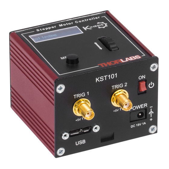
- Page 1 KST101 K-Cube Stepper Motor Controller APT User Guide Original Instructions...
-
Page 2: Table Of Contents
Contents Chapter 1 Safety ..................... 4 1.1 Safety Information .................. 4 1.2 General Warnings .................. 4 Chapter 2 Overview and Setup ..............5 2.1 Introduction ..................... 5 2.2 K-Cube Controller Hub ................6 2.3 APT PC Software Overview ..............7 2.3.1 Introduction ...................... - Page 3 Appendix B Preventive Maintenance ............65 Appendix C Specifications ................66 Appendix D Motor Control Method Summary ........... 68 Appendix E Stepper Motor Operation - Background ........ 72 Appendix F Regulatory ................78 Appendix G Thorlabs Worldwide Contacts ..........81...
-
Page 4: Chapter 1 Safety
Chapter 1 Safety 1.1 Safety Information For the continuing safety of the operators of this equipment, and the protection of the equipment itself, the operator should take note of the Warnings, Cautions and Notes throughout this handbook and, where visible, on the product itself. The following safety symbols may be used throughout the handbook and on the equipment itself. -
Page 5: Chapter 2 Overview And Setup
Although targeted at lower power operations this product is fully featured with a highly flexible and powerful DSP controller that provides a unique high resolution microstepping capability for such a compact unit. The KST101 is optimised for 'out of the box' operation with the Thorlabs range of ZST stepper motor actuators, however its highly flexible parameter set also supports operation a wide range of stepper motors and associated stages/actuators. -
Page 6: K-Cube Controller Hub
For power, a single way wall plug supply (KPS101) is available for powering a single K-Cube Driver. As a further level of convenience when using the new K-Cube Controllers Thorlabs also offers the 3-channel and 6-channel K-Cube Controller Hubs (KCH301 and KCH601). -
Page 7: Apt Pc Software Overview
K-Cube Stepper Motor Controller 2.3 APT PC Software Overview 2.3.1 Introduction As a member of the APT range of controllers, the Stepper Driver K-Cube shares many of the associated software benefits. This includes USB connectivity (allowing multiple units to be used together on a single PC), fully featured Graphical User Interface (GUI) panels, and extensive software function libraries for custom application development. -
Page 8: Aptuser Utility
Chapter 2 2.3.2 APTUser Utility The APTUser application allows the user to interact with a number of APT hardware control units connected to the host PC. This program displays multiple graphical instrument panels to allow multiple APT units to be controlled simultaneously. All basic operating parameters can be altered and, similarly, all operations (such as motor moves) can be initiated. -
Page 9: Apt Config Utility
K-Cube Stepper Motor Controller 2.3.3 APT Config Utility There are many system parameters and configuration settings associated with the operation of the APT Server. Most can be directly accessed using the various graphical panels, however there are several system wide settings that can be made 'off-line' before running the APT software. -
Page 10: Apt Server (Activex Controls)
Basic, Labview, Visual C++, C++ Builder, HPVEE, Matlab, VB.NET, C#.NET and, via VBA, Microsoft Office applications such as Excel and Word. Consider the ActiveX Control supplied for the KST101 stepper driver unit. This Control provides a complete user graphical instrument panel to allow the motor... -
Page 11: Software Upgrades
APT ActiveX Controls collection. This is available either by pressing the F1 key when running the APT server, or via the Start menu, Start\Programs\Thorlabs\APT\APT Help. 2.3.5 Software Upgrades Thorlabs operate a policy of continuous product development and may issue software upgrades as necessary. -
Page 12: Chapter 3 Getting Started
If you experience any problems when installing software, contact Thorlabs on +44 (0)1353 654440 and ask for Technical Support. DO NOT CONNECT THE CONTROLLER TO YOUR PC YET 1) Download the software from www.thorlabs.com. -
Page 13: Mechanical Installation
(KCH301 and KCH601). ) are also available - see Section 2.2. for further details. Full instructions on the fitting and use of the controller hub are contained in the handbook available at www.thorlabs.com. Caution When siting the unit, it should be positioned so as not to impede the operation of the control panel. -
Page 14: Electrical Installation
Fig. 3.2 Rear Panel Connections The rear panel of the unit is fitted with a 15 pin D-type connector as shown above, which is compatible with all new Thorlabs DC servo motor actuators (refer to Appendix A for details of pin outs). - Page 15 POWER - A Standard 3.5 mm front panel jack connector for connecting the unit to a regulated DC power supply of 15 V, 1A. Thorlabs offers a compact, multi-way power supply unit (TPS008), allowing up to eight Driver K-Cubes to be powered from a single mains outlet. A single way wall plug supply (KPS101) for powering a single Driver K-Cube is also available.
-
Page 16: Connect The Hardware
Z F S 2 5 A t + 0 . 0 0 0 0 m m S t o p p e d Fig. 3.4 KST101 start up screens 8) Windows should detect the new hardware. Wait while Windows installs the drivers for the new hardware. -
Page 17: Use With Legacy Actuators And Stages
K-Cube Stepper Motor Controller 3.5 Use with Legacy Actuators and Stages To ensure that a particular stage is driven properly by the system, a number of parameters must first be set. These parameters relate to the physical characteristics of the stage being driven (e.g. min and max positions, leadscrew pitch, homing direction etc.). -
Page 18: Verifying Software Operation
Chapter 3 3.6 Verifying Software Operation 3.6.1 Initial Setup The APT Software should be installed (Section 3.1.) and the stage association performed (Section 3.5.) before software operation can be verified. 1) Ensure power is applied to the unit, then switch the unit ON using the switch on the front panel. - Page 19 K-Cube Stepper Motor Controller Follow the tutorial steps described in Chapter 4 for further verification of operation.’ Note The 'APT Config' utility can be used to set up simulated hardware configurations and place the APT Server into simulator mode. In this way it is possible to create any number and type of simulated (virtual) hardware units in order to emulate a set of real hardware.
-
Page 20: Chapter 4 Standalone Operation
4.1 Introduction The Stepper Driver K-Cube has been designed specifically to operate with lower power stepper motors such as the Thorlabs ZST series, however it can also drive a variety of other stepper motors (15V operation) equipped with or without encoder feedback. -
Page 21: Digital Display - Operating Mode
K-Cube Stepper Motor Controller Digital Display - The display shows the menu options and settings, accessed via the menu button - see Section 4.4. When the Ident button on the associated GUI panel is clicked, the display will flash for a short period. MENU - used to access the settings menu - see Section 4.4. -
Page 22: Velocity Wheel Operation
Chapter 4 is moved up. These ‘taught’ positions can be set through the software GUI - see Section 6.3.3. or via the display menu, see Section 4.4.7. This mode of operation is enabled by setting the ‘Wheel Mode’ to ‘Go To Position’ through the software GUI - see Section 6.3.3. -
Page 23: Settings Menu
K-Cube Stepper Motor Controller 4.4 Settings Menu 4.4.1 Overview A t 0 . 0 0 0 0 m m S t o p p e d Press the MENU button MENU M e n u o p t i o n s Use the wheel to scroll through the menu options U s e w h e e l Press the MENU button to enter a particular option... -
Page 24: Menu Option - Go To Position
Chapter 4 4.4.2 Menu Option - Go to position A t 0 . 0 0 0 0 m m This mode is used to move to an absolute position. S t o p p e d MENU Press the MENU button, then use the wheel to scroll through the menu options. -
Page 25: Menu Option - Start Homing
K-Cube Stepper Motor Controller 4.4.3 Menu Option - Start homing A t 2 . 0 0 0 0 m m This mode is used to home the stage. S t o p p e d MENU Press the MENU button, then use the wheel to scroll through the menu options. -
Page 26: Menu Option - Joystick Mode
Chapter 4 4.4.5 Menu Option - Joystick Mode This mode is used to set the operating mode of the A t 0 . 0 0 0 0 m m H o m e d S t o p p e d V joystick wheel. -
Page 27: Menu Option - Jog Step Size
K-Cube Stepper Motor Controller 4.4.6 Menu Option - Jog Step Size A t 0 . 0 0 0 0 m m This mode is used to set the jog step size. H o m e d S t o p p e d V MENU Press the MENU button, then use the wheel to scroll M e n u o p t i o n s... -
Page 28: Menu Option - Teach Position
Chapter 4 4.4.7 Menu Option - Teach Position This mode is used to set the teach positions, used when the Joystick mode option is set to Jog to positions mode - see Section 4.4.5. To set Teach Position 1... A t 1 0 . 0 0 0 0 m m Move the stage to the position to use as teach position 1. -
Page 29: Menu Option - Brightness
K-Cube Stepper Motor Controller 4.4.8 Menu Option - Brightness A t 0 . 0 0 0 0 m m In certain applications, it may be necessary to adjust the H o m e d S t o p p e d V brightness of the LED display. -
Page 30: Menu Option - Disable
Chapter 4 4.4.10 Menu Option - Disable In certain applications, it may be advantageous to disable the wheel to remove the possibility of unwanted motion due to accidental movement of the wheel. A t 0 . 0 0 0 0 m m H o m e d S t o p p e d V MENU Press the MENU button, then use the wheel to scroll... -
Page 31: Menu Option - Select Stage
K-Cube Stepper Motor Controller 4.4.11 Menu Option - Select stage Note Later version actuators and stages have an identification eprom fitted such that the system will recognise automatically the actuator type and install suitable defaults at start up. In this case, the start up screens will show ‘Stage connected xxx’... -
Page 32: Chapter 5 Pc Operation - Tutorial
Hardware configurations and parameter settings can be saved, which simplifies system set up whenever APT User is run up. Fig. 5.1 Typical APT User Screen 1) If required, perform the stage association as detailed in Section 4.4.11. 2) Run the APT User program - Start/Programs/Thorlabs/APT/APT User. - Page 33 K-Cube Stepper Motor Controller 3) The actuator type recognised/associated is displayed in the ‘Settings’ window. See Section 5.11. and Section 6.3. for further details on the parameter values shown in the ‘Settings’ display. Fig. 5.2 Stepper Driver K-Cube Software GUI The APT User utility will be used throughout the rest of this tutorial to interface with the Stepper Driver K-Cube.
-
Page 34: Homing Motors
Chapter 5 5.3 Homing Motors Homing the motor moves the actuator to the home limit switch and resets the internal position counter to zero. The limit switch provides a fixed datum that can be found after the system has been powered up. Fig. -
Page 35: Moving To An Absolute Position
K-Cube Stepper Motor Controller 5.4 Moving to an Absolute Position Absolute moves are measured in real world units (e.g. millimetres), relative to the Home position. 1) Click the position display. Fig. 5.4 Absolute Position Popup Window 2) Enter 0.3589 into the pop up window 3) Click ‘OK’. -
Page 36: Changing Motor Parameters
Chapter 5 5.5 Changing Motor Parameters Moves are performed using a trapezoidal velocity profile (see Appendix E , Section E.1.3.). The velocity settings relate to the maximum velocities at which a move is performed, and the acceleration at which the motor speeds up from zero to maximum velocity. -
Page 37: Jogging
K-Cube Stepper Motor Controller 5.6 Jogging During PC operation, the motor actuators are jogged using the GUI panel arrow keys. There are two jogging modes available, ‘Single Step’ and ‘Continuous’. In ‘Single Step’ mode, the motor moves by the step size specified in the Step Distance parameter. -
Page 38: Stopping The Stage
Chapter 5 5.7 Stopping the Stage The drive channel is enabled and disabled by clicking the ‘Enable’ button on the GUI panel. The green indicator in the button center is lit when the drive channel is enabled. Disabling the channel removes the drive power. During operation, the stage can be stopped at any time by clicking the ‘Stop’... -
Page 39: Graphical Control Of Motor Positions (Point And Move)
K-Cube Stepper Motor Controller 5.8 Graphical Control Of Motor Positions (Point and Move) The GUI panel display can be changed to a graphical display, showing the position of the motor channel(s). Moves to absolute positions can then be initiated by positioning the mouse within the display and clicking. - Page 40 Chapter 5 Move Mode When ‘Move’ is selected, the motors move to an absolute position which corresponds to the position of the cursor within the screen. To specify a move: 1) Position the mouse within the window. For reference, the absolute motor position values associated with the mouse position is displayed in the 'Cursor Position field.
-
Page 41: Setting Move Sequences
K-Cube Stepper Motor Controller 5.9 Setting Move Sequences This section explains how to set move sequences, allowing several positions to be visited without user intervention. For details on moving to absolute positions initiated by a mouse click – see Section 5.8. - Page 42 Chapter 5 3) Select 'New' to display the 'Move Editor' panel. Fig. 5.11 Move Editor Window Move data is entered/displayed as follows: Dist/Pos: - the distance to move from the current position (if 'Relative' is selected) or the position to move to (if 'Absolute' is selected). Dwell Time: - after the move is performed, the system can be set to wait for a specified time before performing the next move in the sequence.
- Page 43 K-Cube Stepper Motor Controller 5) Enter the required move data into the Move Editor and click OK. The move data is displayed in the main window as shown below. Fig. 5.12 Main Window with Move Data 6) Repeat step 4 as necessary to build a sequence of moves. Move data can be copied, deleted, cut/pasted and edited by right clicking the data line(s) and selecting the appropriate option in the pop up menu (shown below).
-
Page 44: Creating A Simulated Configuration Using Apt Config
To create a simulated configuration proceed as follows: 1) Run the APT Config utility - Start/All Programs/Thorlabs/APT/APT Config. 2) Click the 'Simulator Configuration' tab. Fig. 5.15 APT Configuration Utility - Simulator Configuration Tab 3) Enter ‘LAB1’... - Page 45 4) In the 'Simulator' field, check the ‘Enable Simulator Mode’ box. The name of the most recently used configuration file is displayed in the 'Current Configuration' window. 5) In the ‘Control Unit’ field, select ‘1 Ch Stepper Driver K-Cube (KST101)’.
- Page 46 Chapter 5 6) In the ‘Enter 6 digit serial number’ field, enter the serial number of your stepper drive unit. Note Each physical APT hardware unit is factory programmed with a unique 8 digit serial number. In order to simulate a set of ‘real’ hardware the Config utility allows an 8 digit serial number to be associated with each simulated unit.
-
Page 47: Stage/Axis Tab
APTUser. These parameters should not be altered for pre-defined Thorlabs stages and actuators selected using APT Config, as it may adversely affect the performance of the stage. -
Page 48: Chapter 6 Software Reference
Chapter 6 Software Reference 6.1 Introduction This chapter gives an explanation of the parameters and settings accessed from the APT software running on a PC. For information on the methods and properties which can be called via a programming interface, see Appendix D 6.2 GUI Panel The following screen shot shows the graphical user interface (GUI) displayed when accessing the Stepper Driver K-Cube using the APTUser utility. - Page 49 K-Cube Stepper Motor Controller Travel - displays the range of travel (in millimeters or degrees) of the motor. Moving - lit when the motor is in motion. Enable - applies power to the motor. With the motor enabled, the LED in the button is lit.
-
Page 50: Settings Panel
Chapter 6 6.3 Settings Panel When the 'Settings' button on the GUI panel is clicked, the 'Settings' window is displayed. This panel allows motor operation parameters such as move/jog velocities, and stage/axis information to be modified. Note that all of these parameters have programmable equivalents accessible through the ActiveX methods and properties on this Control (refer to the Programming Guide in the APTServer helpfile for further details and to Section 2.3.4. - Page 51 K-Cube Stepper Motor Controller Accn/Dec - the rate at which the velocity climbs from zero to maximum, and slows from maximum to zero. Note Under certain velocity parameter and move distance conditions, the maximum velocity may never be reached (i.e. the move comprises an acceleration and deceleration phase only).
- Page 52 Chapter 6 Continuous - the motor continues to move until the jog signal is removed (i.e. jog button is released). Stopping - the way in which the jog motion stops when the demand is removed. Immediate - the motor stops quickly, in a non-profiled manner Profiled - the motor stops in a profiled manner using the jog Velocity Profile parameters set above.
- Page 53 K-Cube Stepper Motor Controller is decelerated at ‘a’ so that the final position is approached slowly in a controlled manner. velocity maximum velocity (v) acceleration (slope) a time Fig. 6.4 Graph of a trapezoidal velocity profile The S-curve profile is a trapezoidal curve with an additional 'Bow Value' parameter, which limits the rate of change of acceleration and smooths out the contours of the motion profile.
- Page 54 Chapter 6 manner to the acceleration phase, using the Bow Index to reach the maximum deceleration (D) and then bring the axis to a stop at the destination. Note The higher the Bow Index, then the shorter the BI phases of the curve, and the steeper the acceleration and deceleration phases.
-
Page 55: Stage/Axis Tab
For Thorlabs stages, the APT Config utility can be used to associate a specific stage and axis type with the motor channel (refer to the APT Config helpfile for further details on how to associate a stage and axis). - Page 56 Chapter 6 Min Pos - the stage/actuator minimum position (typically zero). Max Pos - the stage/actuator maximum position. Pitch - the pitch of the motor lead screw (i.e. the distance travelled (in mm or degrees) per revolution of the leadscrew). Units - the ‘real world’...
- Page 57 ‘Steps Per Rev’ parameter is entered as full steps, not microsteps. The system automatically applies a factor of 2048 microsteps per full step. The majority of Thorlabs stepper motor actuators have 200 full steps per rev and no gearbox fitted. For these motors the Steps Per Rev and Gearbox Ratio parameters have values of 200 and 1 respectively.
-
Page 58: Panel/Triggering Tab
Chapter 6 use in absence of a PC. To save the settings to hardware, check the ‘Persist Settings to Hardware’ checkbox before clicking the ‘OK button. Caution The ‘Persist Settings’ functionality is provided to simplify use of the unit in the absence of a PC. When the unit is connected to a PC and is operated via APTUser, the default APTServer settings will be loaded at boot up, even if the ‘Persist Settings’... - Page 59 K-Cube Stepper Motor Controller the Preset Pos. 1 and Preset Pos. 2 parameters, and are measured in number of steps from the home position. Wheel Direction The direction of a move initiated by the velocity wheel is specified as follows: Disabled - The wheel is disabled to remove any unwanted motion due to accidental movement of the wheel.
- Page 60 Chapter 6 Triggering Introduction The K-Cube motor controllers have two bidirectional trigger ports (TRIG1 and TRIG2) that can be used to read an external logic signal or output a logic level to control external equipment. Either of them can be independently configured as an input or an output and the active logic state can be selected High or Low to suit the requirements of the application.
- Page 61 K-Cube Stepper Motor Controller Output Trigger Modes When the Trig 1 Mode and Trig 2 Mode parameters are configured as outputs, the TRIG ports can be used as a general purpose digital output, or to indicate motion status or to produce a trigger pulse at configurable positions as follows: Digital Output - General purpose logic output (set using the LLSetGetDigOPs method).
- Page 62 Chapter 6 PosIntervalFwd 15 mm Pos2 Fwd 12 mm Pos1 Rev StartPosRev 10 mm StartPosFwd Pos1 Fwd Time Trig Voltage Time Fig. 6.8 Position Steps Triggering Example for a move from 0 to 20 mm and back. In forward direction: The first trigger pulse occurs at 10 mm (StartPosFwd), the next trigger pulse occurs after another 5 mm (PosIntervalFwd), the stage then moves to 20 In reverse direction: The next trigger occurs when the stage gets to 12 mm.
-
Page 63: Rotation Stagestab
K-Cube Stepper Motor Controller 6.3.4 Rotation StagesTab Absolute Position Reporting Mode This setting relates to the way in which the angular position is displayed on the GUI panel. There are two options: Equivalent Angle 0 to 360 degrees – The maximum displayed position is 359.99°. If a stage is driven past the 360°... -
Page 64: Appendix A Rear Panel Connector Pinout Details
For Future Use For Future Use Caution DO NOT connect a motor actuator while the K-Cube is powered up. Only use motor drive cables supplied by Thorlabs, other cables may have incompatible wiring. Fig. A.1 MOTOR I/O Connector Pin Identification... -
Page 65: Appendix B Preventive Maintenance
Note The equipment contains no user servicable parts. Only personnel authorized by Thorlabs Ltd and trained in the maintenance of this equipment should remove its covers or attempt any repairs or adjustments. Maintenance is limited to safety testing and cleaning as described in the following sections. -
Page 66: Appendix C Specifications
Appendix C Specifications C.1 Specifications Parameter Value Motor Output Motor Drive Voltage 12-15 V (Depending on Supply) Motor Drive Current 750 m A (peak) Motor Drive Type 12-bit PWM Control Control Algorithm Open Loop Microstepping High Resolution Stepping 2048 Microsteps per Full Step 49,152 Microsteps per Revolution (24 Step Motor)( 409600 Microsteps per Revolution (200 Step Motor) Position Feedback... - Page 67 K-Cube Stepper Motor Controller Recommended Motor Requirements Peak Powers 15 W Step Angle Range 20° to 1.8° Rated Phase Current up to 1 A Peak Motor Mode Current 5 to 20 Ω Coil Resistance (nominal) Coil Inductance (nominal) 2 to 5.5 mH Phases Position Control Open Loop...
-
Page 68: Appendix D Motor Control Method Summary
Appendix D Motor Control Method Summary The 'Motor' ActiveX Control provides the functionality required for a client application to control one or more of the APT series of motor controller units. To specify the particular controller being addressed, every unit is factory programmed with a unique 8-digit serial number. - Page 69 K-Cube Stepper Motor Controller GetHWLimSwitches Gets the limit switch configuration settings. GetJogMode Gets the jogging button operating modes. GetJogMode_Mode Get the jogging button operating mode (returned by value). GetJogMode_StopMode Gets the jogging button stopping mode (returned by value). GetJogStepSize Gets the jogging step size. GetJogStepSize_StepSize Gets the jogging step size (returned by value).
- Page 70 Appendix D GetVelParamLimits Gets the maximum velocity profile parameter limits. GetVelParams Gets the velocity profile parameters. GetVelParams_Accn Gets the move acceleration (returned by value). GetVelParams_MaxVel Gets the move maximum velocity (returned by value). Identify Identifies the controller by flashing unit LEDs. LLGetStatusBits Gets the controller status bits encoded in 32 bit integer.
- Page 71 K-Cube Stepper Motor Controller SetMotorParams Sets the motor gearing parameters. SetPhaseCurrents Sets the coil phase currents. SetPositionOffset Sets the motor position offset. SetPotParams Sets the velocity control potentiometer parameters (Cube drivers). SetRelMoveDist Sets the relative move distance. SetStageAxisInfo Sets the stage axis parameters. SetVelParams Sets the velocity profile parameters.
-
Page 72: Appendix E Stepper Motor Operation - Background
The size of the microstep depends on the resolution of the driver electronics. When used with the Thorlabs Stepper Driver K-Cube,128 microsteps per full step can be achieved, giving a total resolution of 3072 microsteps per revolution for a 24 full step motor. - Page 73 K-Cube Stepper Motor Controller E.1.2 Positive and Negative Moves Positive and negative are used to describe the direction of a move. A positive move means a move from a smaller absolute position to a larger one, a negative move means the opposite. In the case of a linear actuator, a positive move takes the platform of the stage further away from the motor.
- Page 74 Appendix E The S-curve profile is a trapezoidal curve with an additional 'Bow Value' parameter, which limits the rate of change of acceleration and smooths out the contours of the motion profile. The Bow Value is specified in mm/s and is derived from the Bow Index field as follows: The Bow Value is applied in mm/s and is derived from the Bow Index field as follows:...
- Page 75 K-Cube Stepper Motor Controller E.2 Positioning a Stage E.2.1 General Whenever a command is received to move a stage, the movement is specified in motion units, (e.g. millimetres). This motion unit value is converted to microsteps before it is sent to the stage by the APT software. Each motor in the system has an associated electronic counter in the controller, which keeps a record of the net number of microsteps moved.
- Page 76 Appendix E Home position can be found. Movement is allowed right through the switch position in either direction. Datum switch +ve limit switch -ve limit switch (or stop) Linear stage Rotary stage Fig. E.4 Stage limit switches E.2.4 Minimum and Maximum Positions These positions are dependent upon the stage or actuator to which the motors are fitted, and are defined as the minimum and maximum useful positions of the stage relative to the ‘Home’...
- Page 77 K-Cube Stepper Motor Controller E.2.5 Power Saving The current needed to hold a motor in a fixed position is much smaller than the current needed to move it. When a stepper motor is at rest it is advisable to reduce the phase (holding) currents so that the motor does not overheat.
-
Page 78: Appendix F Regulatory
Appendix F Regulatory F.1 Declarations Of Conformity F.1.1 For Customers in Europe See Section F.3. F.1.2 For Customers In The USA This equipment has been tested and found to comply with the limits for a Class A digital device, persuant to part 15 of the FCC rules. These limits are designed to provide reasonable protection against harmful interference when the equipment is operated in a commercial environment. - Page 79 • left over parts of units disassembled by the user (PCB's, housings etc.). If you wish to return a unit for waste recovery, please contact Thorlabs or your nearest dealer for further information. F.2.2 Waste treatment on your own responsibility If you do not return an "end of life"...
- Page 80 Appendix F F.3 CE Certificate HA0362T Rev C Jan 2017...
-
Page 81: Appendix G Thorlabs Worldwide Contacts
Support: techsupport.uk@thorlabs.com www.thorlabs.com email: chinasales@thorlabs.com France Thorlabs SAS Brazil 109, rue des Côtes Thorlabs Vendas de Fotônicos Ltda. 78600 Maisons-Laffitte France Rua Riachuelo, 171 Tel: +33 (0) 970 444 844 São Carlos, SP 13560-110 Fax: +33 (0) 811 381 748 Brazil www.thorlabs.de... - Page 82 Thorlabs Inc. Thorlabs Ltd. 56 Sparta Ave Saint Thomas Place, Ely Newton, NJ07860 Cambridgeshire CB7 4EX, Tel: +1 973 579 7227 Tel: +44 (0) 1353 654440 Fax: +1 973 300 3600 Fax: +44 (0) 1353 654444 www.thorlabs.com www.thorlabs.com...
Need help?
Do you have a question about the KST101 and is the answer not in the manual?
Questions and answers