
Related Manuals for THORLABS KIM101


Summary of Contents for THORLABS KIM101
- Page 1 KIM101 Piezo Inertia Motor Controller APT User Guide Original Instructions HA0385T...
-
Page 2: Table Of Contents
KIM101 K-Cube Piezo Motor Controller Contents Chaper 1 For Introduction ..................1 1.1 Introduction ..................1 1.2 Power Options ..................2 1.3 APT PC Software Overview ............... 3 Chaper 2 Safety ......................8 2.1 Safety Information ................8 2.2 General Warnings ................8 Chaper 3 Installation .................... - Page 3 Appendix A Rear Panel Connector Pinout Details ........49 Appendix B Preventive Maintenance ............50 Appendix C Specifications................51 Appendix D Piezo Operation - Background ..........53 Appendix E Regulatory ................56 Appendix F Thorlabs Worldwide Contacts ..........58 Page 0 Rev D Mar 2020...
-
Page 4: Chaper 1 For Introduction
Chapter 1 Introduction 1.1 Introduction The KIM101 Piezo Inertia Motor Controller is designed to control our series of piezo inertia-driven positioning stages. It offers 4 channels of stand-alone manual control (one channel at a time or in pairs simultaneously) for continuous movement/jogging and also remote PC control via USB. -
Page 5: Power Options
Chapter 1 Introduction this with the user friendly apt™ software (supplied) allows the user to very quickly get up and running with complex move sequences in a short space of time. Advanced custom motion control applications and sequences are also possible using the extensive ActiveX®... -
Page 6: Apt Pc Software Overview
K-Cube Inertia Piezo Motor Driver 1.3 APT PC Software Overview 1.3.1 Introduction As a member of the APT range of controllers, the K-Cube Piezo Inertia Motor Controller shares many of the associated software benefits. This includes USB connectivity (allowing multiple units to be used together on a single PC), fully featured Graphical User Interface (GUI) panels, and extensive software function libraries for custom application development. - Page 7 Chapter 1 Introduction 1.3.2 APTUser Utility The APTUser application allows the user to interact with a number of APT hardware control units connected to the host PC. This program displays multiple graphical instrument panels to allow multiple APT units to be controlled simultaneously. All basic operating parameters can be altered and, similarly, all operations (such as motor moves) can be initiated.
- Page 8 K-Cube Inertia Piezo Motor Driver 1.3.3 APT Config Utility There are many system parameters and configuration settings associated with the operation of the APT Server. Most can be directly accessed using the various graphical panels, however there are several system wide settings that can be made 'off-line' before running the APT software.
- Page 9 Chapter 1 Introduction 1.3.4 APT Server (ActiveX Controls) ActiveX Controls are re-usable compiled software components that supply both a graphical user interface and a programmable interface. Many such Controls are available for Windows applications development, providing a large range of re-usable functionality.
- Page 10 Thorlabs operate a policy of continuous product development and may issue software upgrades as necessary.The latest software can be downloaded from the ‘services’ section of www.thorlabs.com. A utility is provided with the APT Software to assist in firmware upgrades. Note When the firmware is updated, the cooling fans may increase in speed while the unit is reprogrammed.
-
Page 11: Chaper 2 Safety
This product generates, uses and outputs high voltages from the SMC connector (HV Output) that are hazardous and can cause serious injury. In any installation that uses the KIM101 it is the user’s responsibility to ensure adequate insulation and precuations are taken to avoid shock risk. Cables for HV Out must be rated for 250 V RMS. -
Page 12: Chaper 3 Installation
If you experience any problems when installing software, contact Thorlabs on +44 (0)1353 654440 and ask for Technical Support. DO NOT CONNECT THE CONTROLLER TO YOUR PC YET 1) Go to Services/Downloads at www.thorlabs.com and download the APT software. -
Page 13: Mechanical Installation
Chapter 3 Installation 3.2 Mechanical Installation Warning The safety of any system incorporating this equipment is the responsibility of the person performing the installation. 3.2.1 Environmental Conditions Warning Operation outside the following environmental limits may adversely affect operator safety. Location Indoor use only Maximum altitude 2000 m... - Page 14 K-Cube Inertia Piezo Motor Driver 3.2.3 Using the Baseplate The baseplate must be bolted to the worksurface before the K-Cube is fitted, as shown below. The K-cube is then located on two dowels in the baseplate and secured by four clips. Fig.
-
Page 15: Electrical Installation
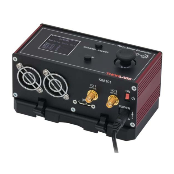
Chapter 3 Installation 3.3 Electrical Installation Caution Ensure that all USB and electrical cables are positively connected and all joints tightened. Loose connections can cause noise and interference problems due to transients from the high switching frequencies 3.3.1 Front Panel Connections I/O 1 I/O 2 Fig. - Page 16 K-Cube Inertia Piezo Motor Driver I/O 1 and I/O 2 - SMA connectors for use with external trigger input and output signals (5V TTL levels). The function is set to trigger IN or OUT via the GUI panel - see Section 6.3.
- Page 17 Section 4.4.8. and Section 6.3. for more details on this mode. MOT Terminals - (SMC Connectors) The unit is supplied with four SMC O/P connectors as shown above, which is compatible with all Thorlabs inertial piezo motor driven positioning stages and actuators.
- Page 18 K-Cube Inertia Piezo Motor Driver 3.3.3 Powering Down The Unit Caution To avoid overheating the unit, do not turn off the power until both fans have stopped. Page 15 ETN040053-D02...
-
Page 19: Connect The Hardware
Asterisk identifies seconds Rev 1 hardware units S t a g e i s P I A S w R e v 0 1 0 0 0 3 * Fig. 3.4 KIM101 start up screen Page 16 Rev D Mar 2020... -
Page 20: Verifying Software Operation
K-Cube Inertia Piezo Motor Driver Selecting the Stage Type To ensure that a particular stage is driven properly by the system, a number of parameters must first be set. These parameters relate to the physical characteristics of the stage/ actuator being driven (e.g. min and max positions, leadscrew pitch, homing direction etc.). To assist in setting these parameters correctly, it is possible to associate a specific stage type with the motor controller channel. -
Page 21: Chaper 4 Standalone Operation
Persons using the KIM101 controller must understand the hazards associated with using high voltages and the steps necessary to avoid risk of electrical shock. If the KIM101 is used in a manner not specified by Thorlabs, the protective features provided by the product may be impaired. -
Page 22: Control Panel Buttons And Indicators
It also shows the menu options and settings, accessed via the menu button - see Section 4.4. When the Ident button on the associated GUI panel is clicked, the display text ‘KIM101’ at the top of the display will flash for a short period. - Page 23 Chapter 4 Standalone Operation The joystick can be used to control the motor in a number of ways as follows, depending on the mode selected in the Joystick Mode menu option - see Section 4.4.6. Caution If the actuator is driven into its end stops, the motor may stick and may not respond to subsequent motion demands.
-
Page 24: Settings Menu
K-Cube Inertia Piezo Motor Driver 4.4 Settings Menu 4.4.1 Overview K I M 1 0 1 After the power up sequence is complete, the normal E n a b l e d A x i s C H 1 operating screen is displayed. C h 1 _ X 1 C h 2 _ Y 1 C h 3 _ X 2... - Page 25 Chapter 4 Standalone Operation Overview (Cont)... K I M 1 0 1 Enable each axis individually or a pair of axes - see M e n u o p t i o n s 7 E n A x i s M o d e Section 4.4.8.
- Page 26 K-Cube Inertia Piezo Motor Driver 4.4.2 Menu Option - Go to position count This option is used to move the motor associated with the K I M 1 0 1 selected channel to a specific position. The position is E n a b l e d A x i s C H 1 measured in cycles (pulses) relative to the zero position, in the range -100000 to 100000.
- Page 27 Chapter 4 Standalone Operation 4.4.3 Menu Option - Zero Axis Zeroing is equivalent to homing in a stepper or DC motor K I M 1 0 1 in that it establishes a datum from which subsequent E n a b l e d A x i s C H 1 position moves can be measured.
- Page 28 K-Cube Inertia Piezo Motor Driver 4.4.4 Menu Option - Set Velocity This option is used to set the max velocity for a specific channel when a move command is initiated K I M 1 0 1 via the GUI panel or via software. It is not applicable E n a b l e d A x i s C H 1 to moves initiated by the joystick (see Section 6.3.2.).
- Page 29 Chapter 4 Standalone Operation 4.4.5 Menu Option - Set Jog Step Size This option is used to set the distance moved when a jog command is initiated. The step size is specified by the K I M 1 0 1 ‘number of cycles’...
- Page 30 K-Cube Inertia Piezo Motor Driver 4.4.6 Menu Option - Joystick Mode This option is used to set the operating mode of the top panel joystick, as detailed in Section 4.3. K I M 1 0 1 In all modes, directional control of the motor is E n a b l e d A x i s C H 1 achieved by moving the joystick in both directions (left and right for CH1 and CH3, or up and down for CH2...
- Page 31 Chapter 4 Standalone Operation 4.4.7 Menu Option - Teach Positions This option is used to set the move positions, when the Joystick mode is set to ‘Jog to Count’ mode (see Section K I M 1 0 1 4.4.6.). E n a b l e d A x i s C H 1 Positions are measured in cycles’...
- Page 32 K-Cube Inertia Piezo Motor Driver 4.4.8 Menu Option - Enable Axis Mode This option is used to set the way in which the motor K I M 1 0 1 axis is enabled from the top panel CHANNEL SELECT button, either a single axis, or a pair of axes. E n a b l e d A x i s C H 1 It is also used to disable the motor axes.
- Page 33 Chapter 4 Standalone Operation 4.4.9 Menu Option - Set Brightness In certain applications, it may be necessary to adjust the brightness of the LCD display. The brightness is set as a K I M 1 0 1 value from 0 (Off) to 100 (brightest). The display can be E n a b l e d A x i s C H 1 turned off completely by entering a setting of zero, however, pressing the MENU button on the top panel will...
- Page 34 K-Cube Inertia Piezo Motor Driver 4.4.10 Menu Option - Set Voltage This option is used to set the maximum piezo drive voltage applied to the actuators in the range 85V to K I M 1 0 1 125V. E n a b l e d A x i s C H 1 C h 1 _ X 1 C h 2 _ Y 1 C h 3 _ X 2...
-
Page 35: Using The External Inputs
Chapter 4 Standalone Operation 4.4.11 Menu Option - Select Stage This ooption allows the type of stage/actuator being driven to be selected. Once this selection has been made, K I M 1 0 1 the server automatically applies suitable default parameter E n a b l e d A x i s C H 1 values on boot up of the software It is important to select the correct stage and axis type. - Page 36 K-Cube Inertia Piezo Motor Driver 4.5.1 Revision 1 Hardware units On legacy Rev 1 hardware units, a 0V input gives max velocity in the reverse direction, whereas 10V input gives max velocity forwards; a 5V input results in no movement. To use the external inputs, the user should apply 5V to the connector and wait 10 to 12 seconds for the unit to recognise a steady 5V input.
-
Page 37: Chaper 5 Pc Operation - Tutorial
Hardware configurations and parameter settings can be saved, which simplifies system set up whenever APT User is run up. Fig. 5.1 Typical APT User Screen 1) Run the APT User program - Start/Programs/Thorlabs/APT/APT User. Page 34 Rev D Mar 2020... -
Page 38: Moving To A Position
K-Cube Inertia Piezo Motor Driver 2) The GUI panel shown below is displayed.. Fig. 5.2 Piezo Motor K-CubeSoftware GUI The APT User utility will be used throughout the rest of this tutorial to interface with the piezo inertia motor controller. 5.3 Moving to a Position Moves are measured in the number of steps, relative to the zero position. -
Page 39: Zeroing
Chapter 5 PC Operation - Tutorial 2) Enter the required number of steps into the pop up window, e.g. 128 3) Click ‘OK’. Notice that the position display counts up to 128 to indicate a move to the absolute position commanded. 5.4 Zeroing To establish a datum from which subsequent position moves can be measured, move the motor to the required zero position, and then click the ZERO button on the GUI... -
Page 40: Current Limits During High Frequency Operation
K-Cube Inertia Piezo Motor Driver 5.8 Current Limits During High Frequency Operation Caution During high frequency operation of two simultaneous channels, the unit can typically draw above 1.2 Amps from the power supply. During this operation very large peak currents can flow in the ground return, which are continually monitored. -
Page 41: Chaper 6 Software Reference
Chapter 6 Software Reference Chapter 6 Software Reference 6.1 Introduction This chapter gives an explanation of the parameters and settings accessed from the APT software running on a PC. 6.2 GUI Panel The following screen shot shows the graphical user interface (GUI) displayed when accessing the Piezo Motor Driver K-Cube using the APTUser utility. -
Page 42: Settings Panel
Jog Rate - The velocity to move when a jog command is initiated. It is specified in drive pulses/sec, in the range 1 to 2,000. Ident - when this button is pressed, the text ‘KIM101’ on the top panel display of the associated hardware unit will flash for a short period. - Page 43 Chapter 6 Software Reference 6.3.1 Moves/Jogs Tab Fig. 6.2 Piezo Motor Driver K-Cube - Move/Jog Settings Caution If a channel pair is enabled (see Section 5.7.) then the step acceleration values are set the same for each channel in the pair, and are taken from the lower channel number, either CH1 or CH3.
- Page 44 K-Cube Inertia Piezo Motor Driver Jogs These parameters define the speed and acceleration of moves by jog command, either from the joystick, GUI panel or via software. Jog Mode - The way in which the motor moves when a jog command is received (i.e. front panel button pressed or GUI panel button clicked).
- Page 45 Chapter 6 Software Reference link. The Move and Jogging parameters described previously are good examples of settings that can be altered and then persisted in the driver for use in absence of a PC. To save the settings to hardware, check the ‘Persist Settings to Hardware’ checkbox before clicking the ‘OK button.
- Page 46 K-Cube Inertia Piezo Motor Driver Go To Position - Deflecting the wheel starts a move from the current position to one of the two predefined “teach” positions. The teach positions are specified in the Preset Pos. 1 and Preset Pos. 2 parameters, and are measured in number of steps from the home position.
- Page 47 Chapter 6 Software Reference in the driver for use in absence of a PC. To save the settings to hardware, check the ‘Persist Settings to Hardware’ checkbox before clicking the ‘OK button. Caution The ‘Persist Settings’ functionality is provided to simplify use of the unit in the absence of a PC.
- Page 48 KIM101 K-Cube Piezo Motor Controller When the port is used as an output it provides a push-pull drive of 5 Volts, with the maximum current limited to approximately 8 mA. The current limit prevents damage when the output is accidentally shorted to ground or driven to the opposite logic state by external circuity.
- Page 49 Chapter 6 Software Reference Output Trigger Modes When the Trig 1 Mode and Trig 2 Mode parameters are configured as outputs, the TRIG ports can be used as a general purpose digital output, or to indicate motion status or to produce a trigger pulse at configurable positions as follows: Digital Output - General purpose logic output (set using the appropriate server message).
- Page 50 KIM101 K-Cube Piezo Motor Controller Pos. Rev. and Pos Interval Fwd/Pos Interval Rev). These modes allow external equipment to be triggered at exact position values. Using the last three modes above, position triggering can be configured to be unidirectional (Trig Out Pos. Steps Fwd or Trig Out Pos. Steps Rev) or bidirectional (Trig Out Pos.
- Page 51 Chapter 6 Software Reference Trig Polarity The polarity of the trigger pulse is specified in the Trig. 1 Polarity and Trig 2 Polarity parameters as follows: Active is High - The active state of the trigger port is logic HIGH 5V (trigger input and output on a rising edge).
-
Page 52: Appendix A Rear Panel Connector Pinout Details
KIM101 K-Cube Piezo Motor Controller Appendix A Rear Panel Connector Pinout Details A.1 Rear Panel USER IO Connector Description Description +5 V OW-A OW-B Limit Switch 3A/Encoder 3A Limit Switch 1A/Encoder 1A Limit Switch 3B/Encoder 3B Limit Switch 1B/Encoder 1B... -
Page 53: Appendix B Preventive Maintenance
The equipment contains no user servicable parts. There is a risk of electrical shock if the equipment is operated with the covers removed. Only personnel authorized by Thorlabs Ltd and trained in the maintenance of this equipment should remove its covers or attempt any repairs or adjustments. Maintenance is limited to safety testing and cleaning as described in the following sections. -
Page 54: Appendix C Specifications
KIM101 K-Cube Piezo Motor Controller Appendix C Specifications and Associated Parts C.1 Specifications Parameter Value Piezoelectric Output (SMC) Voltage Output 85 to 125 V DC/channel External Input (SMA CHA, CHB) Input Type Single Ended, Analog Input Voltage -10 to 10 V ±2%... - Page 55 Appendix C Specifications and Associated Parts C.2 Associated Products Product Name Part Number Piezo Inertia Motor Actuator, 13 mm Travel PIA13 Piezo Inertia Motor Actuator, 25 mm Travel PIA25 Piezo Inertia Motor Actuator, 50 mm Travel, PIA50 Piezo Inertia Motor Actuator, 10 mm Travel, Kinematic Mounting PIAK10 Single Way Power Supply KPS101...
-
Page 56: Appendix D Piezo Operation - Background
KIM101 K-Cube Piezo Motor Controller Appendix D Piezo Operation - Background D.1 Piezoelectric Controller D.1.1 The Piezoelectric Effect Piezoelectricity is the effect whereby certain types of crystal expand reversibly when subjected to an electric field. Although the amount of expansion is usually very small (corresponding to less than 1% strain in the material) it can be controlled extremely finely by varying the strength of the electric field. - Page 57 Some Thorlabs nanopositioning actuators have position sensing, others do not. The Piezoelectric control module allows both types to be controlled.
- Page 58 KIM101 K-Cube Piezo Motor Controller moving open loop control part demand actuator moving closed loop control part demand a + b/s actuator sensor Fig. D.3 Open loop and closed loop control The result of using closed-loop control is a linear relationship between demand (voltage) and measured position –...
-
Page 59: Appendix E Regulatory
Appendix E Regulatory Appendix E Regulatory E.1 Declarations Of Conformity 5.1.1 For Customers in Europe See Section E.2. 5.1.2 For Customers In The USA This equipment has been tested and found to comply with the limits for a Class A digital device, persuant to part 15 of the FCC rules.
Need help?
Do you have a question about the KIM101 and is the answer not in the manual?
Questions and answers