
Subscribe to Our Youtube Channel
Related Manuals for THORLABS KIM001


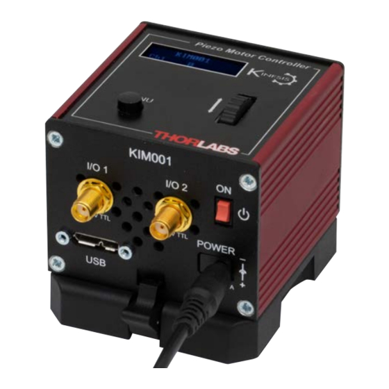
Summary of Contents for THORLABS KIM001
- Page 1 KIM001 Piezo Inertia Motor Controller APT User Guide Original Instructions HA0400T...
-
Page 2: Table Of Contents
KIM001 K-Cube Piezo Motor Controller Contents Chapter 1 Introduction ....................... 1 1.1 Introduction ....................1 1.2 Power Options ..................2 1.3 APT PC Software Overview ..............3 Chapter 2 Safety ........................8 2.1 Safety Information ..................8 2.2 General Warnings ..................8 Chapter 3 Installation ...................... - Page 3 Appendix A Preventive Maintenance ................ 54 Appendix B Specifications and Associated Parts ........... 55 Appendix C Piezo Operation - Background ............. 57 Appendix D Regulatory ....................60 Appendix E Thorlabs Worldwide Contacts .............. 62 Page 0 Rev A Feb 2020...
-
Page 4: Chapter 1 Introduction
Chapter 1 Introduction 1.1 Introduction The KIM001 Piezo Inertia Motor Controller is designed to control our series of piezo inertia-driven actuators and positioning stages. It offers 1 channel of stand-alone manual control for continuous movement/jogging and also remote PC control via USB. -
Page 5: Power Options
Due to the nature of its design, and its non-linear high frequency switching, if the KIM001 unit is fitted to the hub and it is driven at high output frequencies, it may generate electrical noise which could affect the operation of other K-Cubes also fitted to the hub. -
Page 6: Apt Pc Software Overview
K-Cube Inertia Piezo Motor Driver 1.3 APT PC Software Overview 1.3.1 Introduction As a member of the APT range of controllers, the K-Cube Piezo Inertia Motor Controller shares many of the associated software benefits. This includes USB connectivity (allowing multiple units to be used together on a single PC), fully featured Graphical User Interface (GUI) panels, and extensive software function libraries for custom application development. - Page 7 Chapter 1 Introduction 1.3.2 APTUser Utility The APTUser application allows the user to interact with a number of APT hardware control units connected to the host PC. This program displays multiple graphical instrument panels to allow multiple APT units to be controlled simultaneously. All basic operating parameters can be altered and, similarly, all operations (such as motor moves) can be initiated.
- Page 8 K-Cube Inertia Piezo Motor Driver 1.3.3 APT Config Utility There are many system parameters and configuration settings associated with the operation of the APT Server. Most can be directly accessed using the various graphical panels, however there are several system wide settings that can be made 'off-line' before running the APT software.
- Page 9 Chapter 1 Introduction 1.3.4 APT Server (ActiveX Controls) ActiveX Controls are re-usable compiled software components that supply both a graphical user interface and a programmable interface. Many such Controls are available for Windows applications development, providing a large range of re-usable functionality.
- Page 10 Thorlabs operate a policy of continuous product development and may issue software upgrades as necessary.The latest software can be downloaded from the ‘services’ section of www.thorlabs.com. A utility is provided with the APT Software to assist in firmware upgrades. Note When the firmware is updated, the cooling fans may increase in speed while the unit is reprogrammed.
-
Page 11: Chapter 2 Safety
This product generates, uses and outputs high voltages from the SMC connector (HV Output) that are hazardous and can cause serious injury. In any installation that uses the KIM001 it is the user’s responsibility to ensure adequate insulation and precuations are taken to avoid shock risk. Cables for HV Out must be rated for 250 V RMS. -
Page 12: Chapter 3 Installation
If you experience any problems when installing software, contact Thorlabs on +44 (0)1353 654440 and ask for Technical Support. DO NOT CONNECT THE CONTROLLER TO YOUR PC YET 1) Go to Services/Downloads at www.thorlabs.com and download the APT software. -
Page 13: Mechanical Installation
(KCH301 and KCH601) are also available - see Section 1.2. for further details. Full instructions on the fitting and use of the controller hub are contained in the handbook available at www.thorlabs.com. Caution When siting the unit, it should be positioned so as not to impede the operation of the control panel buttons. -
Page 14: Electrical Installation
K-Cube Inertia Piezo Motor Driver 3.2.3 Using the Baseplate The baseplate is supplied with magnets for quick positioning on an optical worksurface. For more secure positioning, it can be bolted to the worksurface before the K-Cube is fitted, as shown below. The K-cube is then located on two dowels in the baseplate and secured by two clips. - Page 15 Chapter 3 Installation Warning: Risk of Electrical Shock The unit must be connected only to a DC supply of 15V, 1A regulated. Connection to a supply of a different rating may cause damage to the unit and could result in injury to the operator. POWER - A Standard 3.5 mm front panel jack connector for connecting the unit to a regulated DC power supply of 15 V, 1A.
- Page 16 +10V input gives max velocity forwards; a 0V input results in no movement. See Section 4.6. for information on how to enable control via these analog inputs. MOTOR - (SMC Connector) Drive connector compatible with all Thorlabs inertial piezo motor driven positioning stages and actuators (PIA series). Caution When making connections to the MOTOR terminal, take care to ensure proper alignment of the connectors before tightening.
-
Page 17: Connect The Hardware
Due to the nature of its design, and its non-linear high frequency switching, if the KIM001 unit is fitted to the hub and it is driven at high output frequencies, it may generate electrical noise which could affect the operation of other K-Cubes also fitted to the hub. -
Page 18: Selecting The Stage Type
K I M 0 0 1 C h 1 Fig. 3.4 KIM001 start up screen After initialization, the displays shows the device part number (KIM001) and the position is steps from the zero position. 3.5 Selecting the Stage Type To ensure that a particular stage is driven properly by the system, a number of parameters must first be set. -
Page 19: Verifying Software Operation
Chapter 3 Installation 3.6 Verifying Software Operation The APT Software should be installed (Section 3.1.) and the controller connected to the actuators (see Section 3.4.) and the PC, before verifying software operation. 1) Run the APTUser utility and check that the Graphical User Interface (GUI) panel appears and is active. -
Page 20: Chapter 4 Standalone Operation
Persons using the KIM001 controller must understand the hazards associated with using high voltages and the steps necessary to avoid risk of electrical shock. If the KIM001 is used in a manner not specified by Thorlabs, the protective features provided by the product may be impaired. -
Page 21: Control Panel Buttons And Indicators
It also shows the menu options and settings, accessed via the menu button - see Section 4.5. When the Ident button on the associated GUI panel is clicked, the display text ‘KIM001’ at the top of the display will flash for a short period. - Page 22 K-Cube Inertia Piezo Motor Driver The wheel can be used to control the motor in a number of ways as follows, depending on the mode selected in the wheel Mode menu option - see Section 4.5.6. Caution If the actuator is driven into its physical end stops, the motor may stick and may not respond to subsequent motion demands.
-
Page 23: Settings Menu
Chapter 4 Standalone Operation 4.5 Settings Menu 4.5.1 Overview After the power up sequence is complete, the normal K I M 0 0 1 operating screen is displayed. C h 1 Press the MENU button to enter the settings mode. MENU M e n u o p t i o n s Use the wheel to scroll through the menu options... - Page 24 K-Cube Inertia Piezo Motor Driver Overview (Cont)... M e n u o p t i o n s Set the voltage - see Section 4.5.10. 9 S e t V o l t a g e Select the stage - see Section 4.5.11. M e n u o p t i o n s 1 0 S e l e c t S t a g e MENU...
- Page 25 Chapter 4 Standalone Operation 4.5.2 Menu Option - Go to position count This option is used to move the motor associated with the K I M 0 0 1 C h 1 controller to a specific position. The position is measured in cycles (pulses) relative to the zero position, in the MENU range -100000 to 100000.
- Page 26 K-Cube Inertia Piezo Motor Driver 4.5.3 Menu Option - Zero Axis K I M 0 0 1 Zeroing is equivalent to homing in a stepper or DC motor C h 1 2 3 0 0 0 in that it establishes a datum from which subsequent position moves can be measured.
- Page 27 Chapter 4 Standalone Operation 4.5.4 Menu Option - Set Velocity This option is used to set the max velocity when a move command is initiated via the GUI panel or via software. It K I M 0 0 1 is not applicable to moves initiated by the wheel (see C h 1 Section 6.3.1.).
- Page 28 K-Cube Inertia Piezo Motor Driver 4.5.5 Menu Option - Set Jog Step Size This option is used to set the distance moved when a jog command is initiated. The step size is specified by the K I M 0 0 1 ‘number of cycles’...
- Page 29 Chapter 4 Standalone Operation 4.5.6 Menu Option - Wheel Mode This option is used to set the operating mode of the top panel wheel, as detailed in Section 4.4. K I M 0 0 1 C h 1 In all modes, directional control of the motor is achieved by moving the wheel up and down.
- Page 30 K-Cube Inertia Piezo Motor Driver 4.5.7 Menu Option - Teach Positions This option is used to set the move positions, when the wheel mode is set to ‘Jog to Count’ mode (see K I M 0 0 1 Section 4.5.6.). C h 1 Positions are measured in cycles’...
- Page 31 Chapter 4 Standalone Operation 4.5.8 Menu Option - Enable Output This option is used to enable and disable the motor axis K I M 0 0 1 from the top panel. C h 1 Press the MENU button, then use the wheel to scroll MENU through the menu options.
- Page 32 K-Cube Inertia Piezo Motor Driver 4.5.9 Menu Option - Set Brightness In certain applications, it may be necessary to adjust the brightness of the LCD display. The brightness is set as a K I M 0 0 1 value from 0 (Off) to 99 (brightest). The display can be C h 1 turned off completely by entering a setting of zero, however, pressing the MENU button on the top panel will...
- Page 33 Chapter 4 Standalone Operation 4.5.10 Menu Option - Set Voltage This option is used to set the maximum piezo drive voltage applied to the actuators in the range 85V to 125V. K I M 0 0 1 C h 1 MENU Press the MENU button, then use the wheel to scroll M e n u o p t i o n s...
- Page 34 K-Cube Inertia Piezo Motor Driver 4.5.11 Menu Option - Select Stage This option allows the type of stage/actuator being driven to be selected. Once this selection has been made, the K I M 0 0 1 C h 1 server automatically applies suitable default parameter values on boot up of the software It is important to select the correct stage and axis type.
-
Page 35: Using The External Inputs
Chapter 4 Standalone Operation 4.6 Using the External Inputs The EXT IN connector on the rear panel (see Fig. 3.3) can be used to control the velocity of the piezo actuator by using a voltage input from an external source. A -10V input gives max velocity in the reverse direction, whereas +10V input gives max velocity forwards;... -
Page 36: Chapter 5 Pc Operation - Tutorial
(such as motor moves) can be initiated. Hardware configurations and parameter settings can be saved, which simplifies system set up whenever APT User is run up. Fig. 5.1 Typical APT User Screen 1) Run the APT User program - Start/Programs/Thorlabs/APT/APT User. Page 33 ETN051885-D02... -
Page 37: Zeroing
Chapter 5 PC Operation - Tutorial 2) The GUI panel shown below is displayed.. Fig. 5.2 Piezo Motor K-CubeSoftware GUI The APT User utility will be used throughout the rest of this tutorial to interface with the piezo inertia motor controller. 5.3 Zeroing To establish a datum from which subsequent position moves can be measured, move the motor to the required zero position, and then click the ZERO button on the GUI... -
Page 38: Changing Motor Parameters
K-Cube Inertia Piezo Motor Driver 1) Click the position display. Fig. 5.3 Position Popup Window 2) Enter the required number of steps into the pop up window, e.g. 128 3) Click ‘OK’. Notice that the position display counts up to 128 to indicate a move to the absolute position commanded. -
Page 39: Graphical Control Of Motor Positions (Point And Move)
Chapter 5 PC Operation - Tutorial 5.7 Graphical Control Of Motor Positions (Point and Move) The GUI panel display can be changed to a graphical display, showing the position of the motor channel(s). Moves to absolute positions can then be initiated by positioning the mouse within the display and clicking. - Page 40 K-Cube Inertia Piezo Motor Driver Move Mode When ‘Move’ is selected, the motors move to an absolute position which corresponds to the position of the cursor within the screen. To specify a move: 1) Position the mouse within the window. For reference, the absolute motor position values associated with the mouse position is displayed in the 'Cursor Position field.
-
Page 41: Setting Move Sequences
Chapter 5 PC Operation - Tutorial 5.8 Setting Move Sequences This section explains how to set move sequences, allowing several positions to be visited without user intervention. 1) From the Motor GUI Panel, select 'Move Sequencer' tab to display the Move Sequencer window. - Page 42 K-Cube Inertia Piezo Motor Driver 3) Select 'New' to display the 'Move Editor' panel. Fig. 5.7 Move Editor Window Move data is entered/displayed as follows: Dist/Pos: - the distance to move from the current position (if 'Relative' is selected) or the position to move to (if 'Absolute' is selected). Dwell Time: - after the move is performed, the system can be set to wait for a specified time before performing the next move in the sequence.
- Page 43 Chapter 5 PC Operation - Tutorial 5) Enter the required move data into the Move Editor and click OK. The move data is displayed in the main window as shown below. Fig. 5.8 Main Window with Move Data 6) Repeat step 4 as necessary to build a sequence of moves. Move data can be copied, deleted, cut/pasted and edited by right clicking the data line(s) and selecting the appropriate option in the pop up menu (shown below).
-
Page 44: Creating A Simulated Configuration Using Apt Config
To create a simulated configuration proceed as follows: 1) Run the APT Config utility - Start/All Programs/Thorlabs/APT/APT Config. 2) Click the 'Simulator Configuration' tab. Fig. 5.11 APT Configuration Utility - Simulator Configuration Tab 3) Enter a suitable name, e.g. - Page 45 Chapter 5 PC Operation - Tutorial 4) In the 'Simulator' field, check the ‘Enable Simulator Mode’ box. The name of the most recently used configuration file is displayed in the 'Current Configuration' window. 5) In the ‘Control Unit’ field, select ‘1Ch Inertial Motor Drive K-Cube (KIM)’. Page 42 Rev A Feb 2020...
- Page 46 8 digits (as displayed in the ‘Load Configuration Details’ window), the first two digits are added automatically and identify the type of control unit. The prefixed digits relating to the KIM001 Inertial Piezo Motor Driver K-Cube are: 74xxxxxx - 1 Ch Inertial Motor Drive K-Cube 7) Click the 'Add' button.
-
Page 47: Chapter 6 Software Reference
Chapter 6 Software Reference Chapter 6 Software Reference 6.1 Introduction This chapter gives an explanation of the parameters and settings accessed from the APT software running on a PC. 6.2 GUI Panel The following screen shot shows the graphical user interface (GUI) displayed when accessing the Piezo Motor Driver K-Cube using the APTUser utility. -
Page 48: Settings Panel
Jog Rate - The velocity to move when a jog command is initiated. It is specified in drive pulses/sec, in the range 1 to 2,000. Ident - when this button is pressed, the text ‘KIM001’ on the top panel display of the associated hardware unit will flash for a short period. - Page 49 Chapter 6 Software Reference 6.3.1 Moves/Jogs Tab Fig. 6.2 Piezo Motor Driver K-Cube - Move/Jog Settings Moves can be initiated via the GUI panel, either by using the jog buttons (see Section 5.6.) or by entering a position value after clicking on the position display box (see Section 5.4.), or by pressing the buttons on the unit.
- Page 50 KIM001 K-Cube Piezo Motor Controller Jogs These parameters define the speed and acceleration of moves by jog command, either from the joystick, GUI panel or via software. Jog Mode - The way in which the motor moves when a jog command is received (i.e.
- Page 51 Chapter 6 Software Reference settings that can be altered and then persisted in the driver for use in absence of a PC. To save the settings to hardware, check the ‘Persist Settings to Hardware’ checkbox before clicking the ‘OK button. Caution The current settings are always saved to the unit (persisted) when the unit is powered down.
- Page 52 KIM001 K-Cube Piezo Motor Controller the Preset Pos. 1 and Preset Pos. 2 parameters, and are measured in number of steps from the home position. In this mode, move the joystick left (Ch1 and 3) or up (Ch 2 and 4) to go to position 1, and right or down to go to position 2.
- Page 53 in the driver for use in absence of a PC. To save the settings to hardware, check the ‘Persist Settings to Hardware’ checkbox before clicking the ‘OK button. Caution The ‘Persist Settings’ functionality is provided to simplify use of the unit in the absence of a PC.
- Page 54 KIM001 K-Cube Piezo Motor Controller when the output is accidentally shorted to ground or driven to the opposite logic state by external circuity. Warning: do not drive the IO ports from any voltage source that can produce an output in excess of the normal 0 to 5 Volt logic level range. In any case the voltage at the TRIG ports must be limited to -0.25 to +5.25 Volts.
- Page 55 Output Trigger Modes When the Trig 1 Mode and Trig 2 Mode parameters are configured as outputs, the TRIG ports can be used as a general purpose digital output, or to indicate motion status or to produce a trigger pulse at configurable positions as follows: Digital Output - General purpose logic output (set using the appropriate server message).
- Page 56 KIM001 K-Cube Piezo Motor Controller Step Count PosIntervalFwd 1500 Pos2 Fwd 1200 Pos1 Rev StartPosRev 1000 StartPosFwd Pos1 Fwd Time Trig Voltage Time Fig. 6.6 Position Steps Triggering Note In the Trig Out Pos. Steps Fwd mode, the StartPos. Fwd value must be reached in the forward direction for the subsequent trigger sequence to be performed correctly.
- Page 57 The equipment contains no user servicable parts. There is a risk of electrical shock if the equipment is operated with the covers removed. Only personnel authorized by Thorlabs Ltd and trained in the maintenance of this equipment should remove its covers or attempt any repairs or adjustments. Maintenance is limited to safety testing and cleaning as described in the following sections.
- Page 58 KIM001 K-Cube Piezo Motor Controller Appendix B Specifications and Associated Parts B.1 Specifications Parameter Value Piezoelectric Output (SMC) Voltage Output 85 to 125 V DC External Input (SMA EXT IN) Input Type Single Ended, Analog Input Voltage -10 to 10 V ±2%...
- Page 59 Appendix B Specifications and Associated Parts B.2 Associated Products Product Name Part Number Piezo Inertia Motor Actuator, 13 mm Travel PIA13 Piezo Inertia Motor Actuator, 25 mm Travel PIA25 Piezo Inertia Motor Actuator, 50 mm Travel, PIA50 Piezo Inertia Motor Actuator, 10 mm Travel, Kinematic Mounting PIAK10 K-Cube Controller USB Hub KCH301 and KCH601...
- Page 60 – see Fig. C.1. In this way, the distance from positive to negative electrodes is very small. A large field gradient can therefore be obtained with a modest drive voltage (75 V in the case of Thorlabs actuators). expansion piezoelectric...
- Page 61 Some Thorlabs nanopositioning actuators have position sensing, others do not. The Piezoelectric control module allows both types to be controlled.
- Page 62 K-Cube Inertia Piezo Motor Driver moving open loop control part demand actuator moving closed loop control part demand a + b/s actuator sensor Fig. C.3 Open loop and closed loop control The result of using closed-loop control is a linear relationship between demand (voltage) and measured position –...
- Page 63 Chapter 6 Software Reference Appendix D Regulatory D.1 Declarations Of Conformity 4.1.1 For Customers in Europe See Section D.2. 4.1.2 For Customers In The USA This equipment has been tested and found to comply with the limits for a Class A digital device, pursuant to part 15 of the FCC rules.
Need help?
Do you have a question about the KIM001 and is the answer not in the manual?
Questions and answers