Sign In
Upload
Download
Table of Contents
Contents
Add to my manuals
Delete from my manuals
Share
URL of this page:
HTML Link:
Bookmark this page
Add
Manual will be automatically added to "My Manuals"
Print this page
×
Bookmark added
×
Added to my manuals
Manuals
Brands
THORLABS Manuals
Controller
KCH301
User manual
THORLABS KCH301 User Manual
K-cube and t-cube usb controller hub and power supply
Hide thumbs
1
Table Of Contents
2
3
4
5
6
7
8
9
10
11
12
13
14
15
16
17
18
19
20
21
22
page
of
22
Go
/
22
Contents
Table of Contents
Bookmarks
Table of Contents
Table of Contents
Chapter 1 For Your Safety
Safety Information
General Warnings
Chapter 2 Overview and Setup
Introduction
Mechanical Installation
Electrical Installation
Using Legacy T-Cubes
Appendix A Connector Pinout Details
Appendix B Preventive Maintenance
Appendix C Specifications
Appendix D Regulatory
Appendix E Thorlabs Worldwide Contacts
Advertisement
Quick Links
Download this manual
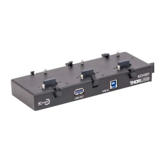
KCH301 and KCH601
K-Cube and T-Cube
USB Controller Hub
and Power Supply
User Guide
Table of
Contents
Previous
Page
Next
Page
1
2
3
4
5
Advertisement
Table of Contents
Need help?
Do you have a question about the KCH301 and is the answer not in the manual?
Ask a question
Questions and answers
Related Manuals for THORLABS KCH301
Controller THORLABS K-Cube Piezo Controller User Manual
Piezo driver apt (78 pages)
Controller THORLABS K-Cube Piezo Controller User Manual
Piezo driver kinesis (68 pages)
Controller THORLABS KST101 User Manual
K-cube stepper motor controller (82 pages)
Controller THORLABS KST101 User Manual
K-cube stepper motor controller (66 pages)
Controller THORLABS KIM101 Original Instructions Manual
Piezo inertia motor controller (59 pages)
Controller THORLABS KIM101 Kinesis User Manual
Piezo inertia motor controller (61 pages)
Controller THORLABS KIM001 User Manual
Piezo inertia motor controller (63 pages)
Controller THORLABS KIM001 User Manual
(56 pages)
Controller THORLABS KSC101 User Manual
K-cube solenoid controller (40 pages)
Controller THORLABS K-Cube KLC101 User Manual
(28 pages)
Controller THORLABS KCH601 User Manual
K-cube and t-cube usb controller hub and power supply (22 pages)
Controller THORLABS KURIOS2 User Manual
Liquid crystal tunable filter controller (37 pages)
Controller THORLABS K-Cube KST201 User Manual
Stepper motor controller (59 pages)
Controller Thorlabs SA201 Operating Manual
Spectrum analyzer controller (20 pages)
Controller THORLABS SC10 Operating Manual
Shutter controller (12 pages)
Controller THORLABS MDT693B User Manual
Open-loop piezo controllers (32 pages)
This manual is also suitable for:
Kch601
Table of Contents
Print
Rename the bookmark
Delete bookmark?
Delete from my manuals?
Login
Sign In
OR
Sign in with Facebook
Sign in with Google
Upload manual
Upload from disk
Upload from URL


Need help?
Do you have a question about the KCH301 and is the answer not in the manual?
Questions and answers