Table of Contents
Advertisement
Quick Links
Advertisement
Table of Contents

Related Manuals for THORLABS K-Cube KLC101


Summary of Contents for THORLABS K-Cube KLC101
- Page 1 KLC101 K-Cube™ Liquid Crystal Controller User Guide...
- Page 2 K-Cube™ Liquid Crystal Controller...
-
Page 3: Table Of Contents
K-Cube™ Liquid Crystal Controller Table of Contents Safety..........................1 Chapter 1 1.1. Safety Information ....................1 1.2. General Warnings ....................1 Overview and Setup ....................2 Chapter 2 2.1. Introduction ......................2 2.2. Power Options ......................4 2.3. PC Software Overview ..................... 4 2.3.1. - Page 4 K-Cube™ Liquid Crystal Controller Regulatory ........................20 Chapter 9 9.1. Declarations Of Conformity .................. 20 9.1.1. For Customers in Europe ..................... 20 9.1.2. For Customers in the USA ................... 20 9.2. CE Certificate ......................21 Chapter 10 Thorlabs Worldwide Contacts .................. 22...
-
Page 6: Chapter 1 Safety
K-Cube™ Liquid Crystal Controller Chapter 1: Safety Safety Chapter 1 1.1. Safety Information For the continuing safety of the operators of this equipment, and the protection of the equipment itself, the operator should take note of the Warnings, Cautions, and Notes throughout this handbook and, where visible, on the product itself. -
Page 7: Chapter 2 Overview And Setup
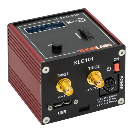
The K-Cube Liquid Crystal Controller (KLC101) is a compact single channel controller/driver for easy manual and automatic control of all Thorlabs Liquid Crystal Variable Retarders and Liquid Crystal Cells with the exception of the LCC2415. The KLC101 produces a square wave output, the frequency of which is adjustable from 500 Hz to 10 kHz, with an amplitude that can be varied from 0 to ±... - Page 8 K-Cube™ Liquid Crystal Controller Chapter 2: Overview and Setup Figure 2 A 2 kHz Square Wave Output The user can also select a modulated output with a frequency range of 0.1 to 150 Hz. The first cycle will be equal to Voltage 1 and the second cycle will be equal to Voltage 2 (see Figure 3). Figure 3 A 1 kHz Square Wave Output with 100 Hz Switching The KLC101 will automatically detect and correct any DC offset in real time to within ±10 mV.
-
Page 9: Power Options
2.2. Power Options For power, a compact two-way power supply unit (TPS002) is available from Thorlabs allowing up to 2 K-Cube Liquid Crystal Controllers to be powered from a single outlet. This power supply unit is also designed to take up minimal space and can be mounted to the optical table in close proximity to the driver units, connected via short power leads. -
Page 10: Chapter 3 Getting Started
If you are in any doubt about your rights to install/run software, please consult your system administrator before attempting to install. If you experience any problems when installing software, contact Thorlabs Technical Support. Note This section is applicable only if the K-Cube is to be used with a PC. If your application consists only of local operation via the K-Cube front face, proceed to Chapter 4. -
Page 11: Using The Baseplate
K-Cube™ Liquid Crystal Controller Chapter 3: Getting Started 3.2.3. Using the Baseplate The baseplate must be bolted to the worksurface before the K-Cube is fitted, as shown below. The K-cube is then placed on two dowels in the baseplate and secured by two clips. Figure 4 Using The Baseplate 3.3. -
Page 12: Front Panel
K-Cube™ Liquid Crystal Controller Chapter 3: Getting Started 3.3.3. Front Panel Warning The unit must be connected only to a DC supply as detailed in Section 3.3. Connection to a supply of a different rating may cause damage to the unit and could result in injury to the operator. Caution Ensure the power switch on the front panel of the unit is switched off before connecting power to the K- Cube. -
Page 13: Powering Down The Unit
K-Cube™ Liquid Crystal Controller Chapter 3: Getting Started Thorlabs offers a compact, two-way power supply unit (TPS002), allowing up to two K-Cubes to be powered from a single outlet. However, if an external supply is to be used, see Section 5.1.1 for power supply connector pin out details. -
Page 14: Chapter 4 Standalone Operation
K-Cube™ Liquid Crystal Controller Chapter 4: Standalone Operation Standalone Operation Chapter 4 4.1. Control Panel Operating Elements Scrolling Wheel - Used to make menu selections and to choose voltage and frequency values with either forward or reverse scrolling - see Section 4.1.3. Digital Display - The display shows the menu options and settings, accessed via the menu button - see Section 4.1.1. -
Page 15: Menu Option - Lc Output
K-Cube™ Liquid Crystal Controller Chapter 4: Standalone Operation Menu options Set the Trigger input/output mode - see Section 4.1.5. 4 Trigger mode Menu options Set wheel adjust lock or unlock - see Section 4.1.6. 5 Wheel lock Menu options Set the display brightness - see Section 4.1.7. 6 Brightness Menu options Set the display timeout period - see Section 4.1.8. -
Page 16: Menu Option - Lc Config
K-Cube™ Liquid Crystal Controller Chapter 4: Standalone Operation 4.1.3. Menu Option - LC Config When using the wheel to set the output Voltage and Frequency, there are three speed modes to quickly get the desired voltage. When the user moves the scroll wheel quickly, the value will increase or decrease by 0.1; when scrolling the wheel at medium speed, the value will increase or decrease by 0.01;... -
Page 17: Menu Option - Trigger Mode
K-Cube™ Liquid Crystal Controller Chapter 4: Standalone Operation 4.1.5. Menu Option – Trigger Mode The K-Cube liquid crystal controller has two bidirectional trigger ports (TRIG1 and TRIG2) that can be used to read an external logic signal or output a logic level to control external equipment. Electrically, the ports output 5 V logic signals and are designed to be driven from a 5 V logic. -
Page 18: Menu Option - Brightness
K-Cube™ Liquid Crystal Controller Chapter 4: Standalone Operation 4.1.7. Menu Option – Brightness For certain applications, it may be necessary to adjust the brightness of the LED display. The brightness is set as a value from 0 (Off) to 100 (brightest). The display can be turned off completely by entering a setting of zero; however, pressing the MENU button on the top panel will temporarily illuminate the display at its lowest brightness setting to allow adjustments. -
Page 19: Normal Operation
K-Cube™ Liquid Crystal Controller Chapter 4: Standalone Operation 4.2.2. Normal Operation The software features a master switch to swtich on/off the main output of the KLC101 and a wheel lock swtich to enable/disable the wheel on the KLC101 front panel. In normal operation, the GUI allows easy switching among the output mode as shown below: Preset 1: in which the KLC101 outputs a signal according to the value set in Voltage 1 and Frequency 1. -
Page 20: Sweeping Mode
K-Cube™ Liquid Crystal Controller Chapter 4: Standalone Operation The entire sequence can be set to just play once (infinite) or to play by a number of cycles. Figure 9 Generating Sequence 4.2.4. Sweeping Mode The software GUI also has a sweeping mode in which users can set a start voltage, an end voltage, step size and step duration. -
Page 21: Chapter 5 Connector Pinout Details
Power Connector 5.1.1. Pin Identification Thorlabs recommends that the liquid crystal cube controller is operated with the Thorlabs TPS002 Power Supply, as it was specifically designed for use with this product. However, to enable customers to use the cube in installations where a ±15 V and 5 V power is already available, the piezo cube can be operated with a different external power supply, such as a bench or lab supply. -
Page 22: Chapter 6 Preventive Maintenance
The equipment contains no user servicable parts. There is a risk of electrical shock if the equipment is operated with the covers removed. Only personnel authorized by Thorlabs and trained in the maintenance of this equipment should remove its covers or attempt any repairs or adjustments. -
Page 23: Chapter 7 Mechanical Drawings
K-Cube™ Liquid Crystal Controller Chapter 7: Mechanical Drawings Mechanical Drawings Chapter 7 Page 18 CTN014867-D02... -
Page 24: Chapter 8 Specifications & Accessories
K-Cube™ Liquid Crystal Controller Chapter 8: Specifications & Accessories Specifications & Accessories Chapter 8 8.1. Specifications Parameter Value Electrical Characteristics Adjustable Output Voltage 0 to ±25 V RMS Voltage Resolution 1.0 mV 500 Hz to 10 kHz, 50% Duty Square Adjustable Output Frequency Wave Adjustable Internal Switching Frequency... -
Page 25: Chapter 9 Regulatory
Waste Treatment is Your Own Responsibility If you do not return an “end of life” unit to Thorlabs, you must hand it to a company specialized in waste recovery. Do not dispose of the unit in a litter bin or at a public waste disposal site. -
Page 26: Ce Certificate
K-Cube™ Liquid Crystal Controller Chapter 9: Regulatory 9.2. CE Certificate Rev A, September 11, 2020 Page 21... -
Page 27: Chapter 10 Thorlabs Worldwide Contacts
K-Cube™ Liquid Crystal Controller Chapter 10: Thorlabs Worldwide Contacts Thorlabs Worldwide Contacts Chapter 10 For technical support or sales inquiries, please visit us at www.thorlabs.com/contact for our most up-to-date contact information. USA, Canada, and South America UK and Ireland Thorlabs, Inc. - Page 28 www.thorlabs.com...
Need help?
Do you have a question about the K-Cube KLC101 and is the answer not in the manual?
Questions and answers