Table of Contents
Advertisement
Quick Links
This legacy APT manual is provided for reference only. Our APT software was
discontinued on July 1, 2024, and no updates have been made to this document since
then. The latest product specifications are contained within the item-specific
documentation at www.thorlabs.com
KST201
K-Cube Stepper Motor Controller
APT User Guide
Original Instructions
Advertisement
Table of Contents

Related Manuals for THORLABS K-Cube KST201


Summary of Contents for THORLABS K-Cube KST201
- Page 1 This legacy APT manual is provided for reference only. Our APT software was discontinued on July 1, 2024, and no updates have been made to this document since then. The latest product specifications are contained within the item-specific documentation at www.thorlabs.com KST201 K-Cube Stepper Motor Controller...
-
Page 2: Table Of Contents
K-Cube Stepper Motor Controller Table of Contents Chapter 1 Safety Information ..................... 1 Chapter 2 Overview ......................2 2.3.1 Introduction ..............................3 2.3.2 APTUser Utility ............................4 2.3.3 APT Config Utility ............................5 2.3.4 APT Server (ActiveX Controls) ........................5 2.3.5 Software Upgrades ............................ - Page 3 11.2.2 Home position ............................51 11.2.3 Limit Switches ............................51 11.2.4 Minimum and Maximum Positions ......................52 11.2.5 Power Saving ............................52 11.3.1 Backlash correction ........................... 53 Chapter 12 Certifications and Compliance ..............54 Chapter 13 Thorlabs Worldwide Contacts ............... 55...
-
Page 4: Chapter 1 Safety Information
K-Cube Stepper Motor Controller Chapter 1: Safety Information Chapter 1 Safety Information For the continuing safety of the operators of this equipment, and the protection of the equipment itself, the operator should take note of the Warnings, Cautions and Notes throughout this handbook and, where visible, on the product itself. -
Page 5: Chapter 2 Overview
DSP controller that provides a unique high-resolution microstepping capability for such a compact unit. The KST201 is optimized for 'out of the box' operation with the Thorlabs range of ZST and ZFS stepper motor actuators, however its highly flexible parameter set also supports operation a wide range of stepper motors and associated stages/actuators. -
Page 6: Introduction
K-Cube Stepper Motor Controller Chapter 2: Overview with multiple K-Cube operation in mind to simplify issues such as cable management, power supply routing, multiple USB device communications and different optical table mounting scenarios. The K-Cube Controller Hub comprises a slim base-plate type carrier with electrical connections located on the upper surface to accept the K-Cubes. -
Page 7: Aptuser Utility
K-Cube Stepper Motor Controller Chapter 2: Overview 2.3.2 APTUser Utility The APTUser application allows the user to interact with several APT hardware control units connected to the host PC. This program displays multiple graphical instrument panels to allow multiple APT units to be controlled simultaneously. -
Page 8: Apt Config Utility
K-Cube Stepper Motor Controller Chapter 2: Overview 2.3.3 APT Config Utility There are many system parameters and configuration settings associated with the operation of the APT Server. Most can be directly accessed using the various graphical panels, however there are several system wide settings that can be made 'off-line' before running the APT software. -
Page 9: Software Upgrades
APT ActiveX Controls collection. This is available either by pressing the F1 key when running the APT server, or via the Start menu, Start\Programs\Thorlabs\APT\APT Help. 2.3.5 Software Upgrades Thorlabs operate a policy of continuous product development and may issue software upgrades as necessary. Page 6 ETN063585-D02... -
Page 10: Chapter 3 Getting Started
If you are in any doubt about your rights to install/run software, please consult your system administrator before attempting to install. If you experience any problems when installing software, contact Thorlabs on +44 (0)1353 654440 and ask for Technical Support. -
Page 11: Using The Baseplate
Rear Panel Connections The rear panel of the unit is fitted with a 15 pin D-type connector as shown above, which is compatible with all new Thorlabs DC servo motor actuators (refer to Chapter 7 for details of pin outs). Caution DO NOT connect a motor actuator while the K-Cube is powered up. -
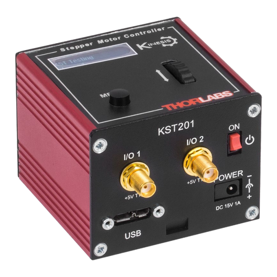
Page 12: Front Panel
K-Cube Stepper Motor Controller Chapter 3: Getting Started 3.4.2 Front Panel Figure 8 Front Panel Power Supply Connections Warning: Risk of Electrical Shock The unit must be connected only to a DC supply of 15V, 1A regulated. Connection to a supply of a different rating may cause damage to the unit and could result in injury to the operator. - Page 13 K-Cube Stepper Motor Controller Chapter 3: Getting Started Note The USB cable should be no more than 3 meters in length. Communication lengths more than 3 meters can be achieved by using a powered USB hub). 4. Connect the stepper motor actuator to the Controller unit- refer to section 3.4.1. Caution During item (5) ensure the power switch on the front panel of the unit is switched off before connecting power to the K-Cube.
-
Page 14: Verifying Software Operation
K-Cube Stepper Motor Controller Chapter 3: Getting Started Note If the actuator/stage has been recognized automatically via the eprom, the startup screens will display ‘Stage connected xxxx’ as shown in Figure 7. If the stage is not fitted with an eprom, the display will show the last stage type persisted, e.g., Stage persisted: ZST13B. -
Page 15: Chapter 4 Standalone Operation
The Stepper Driver K-Cube has been designed specifically to operate with lower power stepper motors such as the Thorlabs ZST and ZFS series, however it can also drive a variety of other stepper motors (15V operation) equipped with or without encoder feedback. -
Page 16: Digital Display- Operating Mode
K-Cube Stepper Motor Controller Chapter 4: Standalone Operation 4.2.1 Digital Display- Operating Mode During normal operation, the digital display shows the current position (in millimeters or degrees) and the current state of the motor (Stopped or Moving). If the stage being driven has been homed, the display will also show ‘Homed’. -
Page 17: Velocity Moves
K-Cube Stepper Motor Controller Chapter 4: Standalone Operation Once set to this mode, the jogging parameters for the wheels are taken from the ‘Jog’ parameters on the ‘Move/Jogs’ settings tab or via the display menu, refer to section 4.4.6. 4.3.4 Velocity Moves Lastly, the wheel can be used to initiate a move at a specified velocity. -
Page 18: Menu Option - Go To Position
K-Cube Stepper Motor Controller Chapter 4: Standalone Operation 4.4.2 Menu Option - Go To Position This mode is used to move to an absolute position. Press the MENU button, then use the wheel to scroll through the menu options. Press the MENU button to enter the Go to positions option. Use the wheel to adjust the position value, (within the travel range for linear stages, or 0 to 360 °... -
Page 19: Menu Option - Velocity
K-Cube Stepper Motor Controller Chapter 4: Standalone Operation 4.4.4 Menu Option - Velocity This mode is used to move to set the max velocity. Press the MENU button, then use the wheel to scroll through the menu options. Press the MENU button to enter the Velocity option. Use the wheel to adjust the max velocity, e.g., 0.168 mm/s, then press the MENU button to store the setting. -
Page 20: Menu Option - Jog Step Size
K-Cube Stepper Motor Controller Chapter 4: Standalone Operation 4.4.6 Menu Option - Jog Step Size This mode is used to set the jog step size. Press the MENU button, then use the wheel to scroll through the menu options. Press the MENU button to enter the Jog step size option. Use the wheel to adjust the step size, e.g., 0.10 mm, then press the MENU button to store the selection. -
Page 21: Menu Option - Brightness
K-Cube Stepper Motor Controller Chapter 4: Standalone Operation 4.4.8 Menu Option - Brightness In certain applications, it may be necessary to adjust the brightness of the LED display. The brightness is set as a value from 0 (Off) to 100 (brightest). The display can be turned off completely by entering a setting of zero, however, pressing the MENU button on the top panel will temporarily illuminate the display at its lowest brightness setting to allow adjustments. -
Page 22: Menu Option - Disable
K-Cube Stepper Motor Controller Chapter 4: Standalone Operation 4.4.10 Menu Option - Disable In certain applications, it may be advantageous to disable the wheel to remove the possibility of unwanted motion due to accidental movement of the wheel. Press the MENU button, then use the wheel to scroll through the menu options. -
Page 23: Chapter 5 Pc Operation - Tutorial
Perform the following: 1. If required perform the stage association as detailed in Section 4.4.11. 2. Run the APT software – Start/All Programs/Thorlabs/APT/APT User. 3. The actuator type is displayed in the ‘Settings’ window. Refer section 6.3 for further details on the parameter values shown in the ‘Settings’... -
Page 24: Homing Motors
K-Cube Stepper Motor Controller Chapter 5: PC Operation – Tutorial The APT User utility will be used throughout the rest of this tutorial to interface with the Stepper Driver K- Cube. Homing Motors Homing the motor moves the actuator to the home limit switch and resets the internal position counter to zero. -
Page 25: Changing Motor Parameters
K-Cube Stepper Motor Controller Chapter 5: PC Operation – Tutorial Changing Motor Parameters Moves are performed using a trapezoidal or S-Curve velocity profile (refer to section 11.1.3). The velocity settings relate to the maximum velocity at which a move is performed, and the acceleration at which the motor speeds up from zero to maximum velocity. - Page 26 K-Cube Stepper Motor Controller Chapter 5: PC Operation – Tutorial Jogging During PC operation, the motor actuators are jogged using the GUI panel arrow keys. There are two jogging modes available, ‘Single Step’ and ‘Continuous’. In ‘Single Step’ mode, the motor moves by the step size specified in the Step Distance parameter.
-
Page 27: Graphical Control Of Motor Positions (Point And Move)
K-Cube Stepper Motor Controller Chapter 5: PC Operation – Tutorial During operation, the stage can be stopped at any time by clicking the ‘Stop’ button on the GUI panel. Using this button does not remove power to the drive channel. Figure 19 APT GUI User Screen Graphical Control of Motor Positions (point and Move) - Page 28 K-Cube Stepper Motor Controller Chapter 5: PC Operation – Tutorial The vertical divisions relate to the travel of the stage/actuator associated with the Stepper Driver K-Cube (the stage/actuator is selected in the ‘APT Config’ utility). For example, the screen shot above shows the parameters for a 25mm travel ZFS25(B) motor actuator.
- Page 29 K-Cube Stepper Motor Controller Chapter 5: PC Operation – Tutorial 2. Right Click in the move data field to display the pop-up menu. Figure 22 Move Sequencer Pop Up Menu 3. Select ‘New’ to display the ‘Move Editor’ panel. Figure 23 Move Editor Window Move data is entered/displayed as follows: Dist/Pos: - the distance to move from the current position (if 'Relative' is selected) or the position to move to...
- Page 30 K-Cube Stepper Motor Controller Chapter 5: PC Operation – Tutorial 4. Enter the required move data into the Move Editor and click OK. The move data is displayed in the main window as shown below. Figure 24 Main Window with Move Data 5.
- Page 31 To create a simulated configuration, perform the following: 1. Run the APT Config utility- Strat/All Programs/Thorlabs/APT/APT Config. 2. Click the ‘Simulator Configuration’ tab. Figure 27 APT Configuration Utility –...
- Page 32 K-Cube Stepper Motor Controller Chapter 5: PC Operation – Tutorial 5. In the ‘Control Unit’ field, select the ‘1 Ch Stepper Drive K-Cube (KST201)’. Figure 29 APT Configuration Utility - Control Unit 6. Enter the serial number of the stepper drive unit in the ‘Enter 6-digit serial number’ field. Note Each physical APT hardware unit is factory programmed with a unique 8 digit serial number.
-
Page 33: Chapter 6 Software Reference
K-Cube Stepper Motor Controller Chapter 6: Software Reference Chapter 6 Software Reference Introduction This chapter explains the parameters and settings accessed from the APT software running on a PC. For information on the methods and properties which can be called via a programming interface, refer Chapter GUI Panel The following screen shot shows the graphical user interface (GUI) displayed when accessing the stepper controller using the APTUSer utility. - Page 34 K-Cube Stepper Motor Controller Chapter 6: Software Reference Driver - the type of control unit associated with the specified channel. Stage - the stage type and axis associated with the specified channel. Note By default, the software associates a ZST6 type actuator, unless the user has used the APTConfig utility to associate a particular stage.
-
Page 35: Moves/Jogs Tab
K-Cube Stepper Motor Controller Chapter 6: Software Reference 6.3.1 Moves/Jogs Tab Figure 31 Stepper Driver K-Cube – Move/Jog Settings Moves - Velocity Profile Moves can be initiated via the GUI panel, by using the velocity wheel (see Section 4.3) or by entering a position value after clicking on the position display box (see Section 5.4). - Page 36 K-Cube Stepper Motor Controller Chapter 6: Software Reference repeated until the button is released – see Figure 32. In ‘Continuous’ mode, the motor actuator will accelerate and move at the jog velocity while the button is held down. Figure 32 Jog Modes Single Step - the motor moves by the step size specified in the Step Distance parameter.
- Page 37 K-Cube Stepper Motor Controller Chapter 6: Software Reference In a typical trapezoidal velocity profile, (see Figure 33), the stage is ramped at acceleration ‘a’ to a maximum velocity ‘v’. As the destination is approached, the stage is decelerated at ‘a’ so that the final position is approached slowly in a controlled manner.
-
Page 38: Stage/Axis Tab
These parameters should not be altered for predefined Thorlabs stages selected using APT Config, as it may adversely affect the performance of the stage. Stage and Axis Type – For Thorlabs stages, the stage type is displayed automatically once the axis has been associated using the APTConfig Utility. - Page 39 K-Cube Stepper Motor Controller Chapter 6: Software Reference Caution Extreme care must be taken when modifying the stage related settings that follow. Some settings are self-consistent with respect to each other, and illegal combinations of settings can result in incorrect operation of the physical motor/stage combination being driven. Min Pos - the stage/actuator minimum position (typically zero).
- Page 40 The system automatically applies a factor of 2048 microsteps per full step. The majority of Thorlabs stepper motor actuators have 200 full steps per rev and no gearbox fitted. For these motors the Steps Per Rev and Gearbox Ratio parameters have values of 200 and 1 respectively.
-
Page 41: Panel/Triggering Tab
K-Cube Stepper Motor Controller Chapter 6: Software Reference 6.3.3 Panel/Triggering Tab Figure 36 Stepper Driver K-Cube Advanced Settings Adjustment Wheel Settings The velocity wheel is sprung such that when released it returns to its central position. In this central position the motor is stationary. - Page 42 K-Cube Stepper Motor Controller Chapter 6: Software Reference Display Brightness In certain applications, it may be necessary to adjust the brightness of the LED display on the top of the unit. The brightness is set in the Active Level parameter, as a value from 0 (Off) to 100 (brightest). The display can be turned off completely by entering a setting of zero, however, pressing the MENU button on the top panel will temporarily illuminate the display at its lowest brightness setting to allow adjustments.
- Page 43 K-Cube Stepper Motor Controller Chapter 6: Software Reference Disabled - The trigger IO is disabled. Digital Input - General purpose logic input (read through status bits using the LLGetStatusBits method). Trig In Rel. Move - Input trigger for relative move. Trig In Abs.
- Page 44 K-Cube Stepper Motor Controller Chapter 6: Software Reference Figure 37 Position Steps Triggering Example for a move from 0 to 20 mm and back. In forward direction: The first trigger pulse occurs at 10 mm (StartPosFwd), the next trigger pulse occurs after another 5 mm (PosIntervalFwd), the stage then moves to 20 mm.
-
Page 45: Rotation/Stages Tab
K-Cube Stepper Motor Controller Chapter 6: Software Reference 6.3.4 Rotation/Stages Tab Figure 38 Rotation Stages Tab Absolute Position Reporting Mode This setting relates to the way in which the angular position is displayed on the GUI panel. There are two options: Equivalent Angle 0 to 360 degrees –... -
Page 46: Chapter 7 Rear Panel Connector Pinout Details
Figure 39 Motor I/O Connector Pin Identification Caution DO NOT connect a motor actuator while the K-Cube is powered up. Only use motor drive cables supplied by Thorlabs, other cables may have incompatible wiring. Rev. A, August 9, 2023 Page 43... -
Page 47: Chapter 8 Preventive Maintenance
Warning The equipment contains no user serviceable parts. Only personnel authorized by Thorlabs Ltd and trained in the maintenance of this equipment should remove its covers or attempt any repairs or adjustments. Maintenance is limited to safety testing and cleaning as described in the following sections. -
Page 48: Chapter 9 Specifications
K-Cube Stepper Motor Controller Chapter 9: Specifications Chapter 9 Specifications Item # KST201 Motor Output Motor Drive Voltage 12-15V (Depending on Supply) Motor Drive Current 750 m A (peak) Motor Drive type 12-bit PWM Control Control Algorithm Open Loop Microstepping 2048 Microsteps per Full Step 49,152 Microsteps per Revolution (24 Step High Resolution Stepping... -
Page 49: Chapter 10 Motion Control Method Summary
K-Cube Stepper Motor Controller Chapter 10: Motion Control Method Summary Chapter 10 Motion Control Method Summary The 'Motor' ActiveX Control provides the functionality required for a client application to control one or more of the APT series of motor controller units. To specify the controller being addressed, every unit is factory programmed with a unique 8-digit serial number. - Page 50 K-Cube Stepper Motor Controller Chapter 10: Motion Control Method Summary GetKCubeTriggerParams Gets the operating parameters of the TRIG1 and TRIG2 connectors on the front panel. GetMotorParams Gets the motor gearing parameters. GetPhaseCurrents Gets the coil phase currents. GetPosition Gets the current motor position. GetPosition_Position Gets the current motor position (returned by value).
- Page 51 K-Cube Stepper Motor Controller Chapter 10: Motion Control Method Summary SetKCubePosTriggerParams Sets operating parameters used when the triggering mode is set to a trigger out position steps mode. SetKCubeTriggerParams Sets the operating parameters of the TRIG1 and TRIG2 connectors on the front panel of the unit.
-
Page 52: Chapter 11 Stepper Motor Operation - Background
(microstep). The size of the microstep depends on the resolution of the driver electronics. When used with the Thorlabs Stepper Driver K-Cube,128 microsteps per full step can be achieved, giving a total resolution of 3072 microsteps per revolution for a 24 full step motor. - Page 53 K-Cube Stepper Motor Controller Chapter 11: Stepper Motor Operation - Background The system incorporates a trajectory generator, which performs calculations to determine the instantaneous position, velocity and acceleration of each axis at any given moment. During a motion profile, these values will change continuously.
-
Page 54: General
K-Cube Stepper Motor Controller Chapter 11: Stepper Motor Operation - Background using the Bow Index to reach the maximum deceleration (D) and then bring the axis to a stop at the destination. Note The higher the Bow Index, then the shorter the BI phases of the curve, and the steeper the acceleration and deceleration phases. -
Page 55: Minimum And Maximum Positions
K-Cube Stepper Motor Controller Chapter 11: Stepper Motor Operation - Background Figure 43 Stage Limit Switches 11.2.4 Minimum and Maximum Positions These positions are dependent upon the stage or actuator to which the motors are fitted and are defined as the minimum and maximum useful positions of the stage relative to the ‘Home’... -
Page 56: Backlash Correction
K-Cube Stepper Motor Controller Chapter 11: Stepper Motor Operation - Background Error Correction 11.3.1 Backlash correction The term backlash refers to the tendency of the stage to reach a different position depending on the direction of approach. Backlash can be overcome by always making the last portion of a move in the same direction, conventionally the positive direction. -
Page 57: Chapter 12 Certifications And Compliance
K-Cube Stepper Motor Controller Chapter 12: Certifications and Compliance Chapter 12 Certifications and Compliance Page 54 ETN063585-D02... -
Page 58: Chapter 13 Thorlabs Worldwide Contacts
K-Cube Stepper Motor Controller Chapter 13: Thorlabs Worldwide Contacts Chapter 13 Thorlabs Worldwide Contacts For technical support or sales inquiries, please visit us at for our most up-to-date www.thorlabs.com/contact contact information. USA, Canada, and South America UK and Ireland Thorlabs, Inc. - Page 59 www.thorlabs.com...
Need help?
Do you have a question about the K-Cube KST201 and is the answer not in the manual?
Questions and answers