Sign In
Upload
Download
Table of Contents
Contents
Add to my manuals
Delete from my manuals
Share
URL of this page:
HTML Link:
Bookmark this page
Add
Manual will be automatically added to "My Manuals"
Print this page
×
Bookmark added
×
Added to my manuals
Manuals
Brands
THORLABS Manuals
Controller
ITC4000 Series
Operation manual
THORLABS ITC4000 Series Operation Manual
Laser diode current and temperature controller
Hide thumbs
1
2
Table Of Contents
3
4
5
6
7
8
9
10
11
12
13
14
15
16
17
18
19
20
21
22
23
24
25
26
27
28
29
30
31
32
33
34
35
36
37
38
39
40
41
42
43
44
45
46
47
48
49
50
51
52
53
54
55
56
57
58
59
60
61
62
63
64
65
66
67
68
69
70
71
72
73
74
75
76
77
78
79
80
81
82
83
84
85
86
87
88
89
90
91
92
93
94
95
96
97
98
99
100
101
102
103
104
105
page
of
105
Go
/
105
Contents
Table of Contents
Troubleshooting
Bookmarks
Table of Contents
Table of Contents
Foreword
1 General Information
Safety
Protection of Laser Diodes
Ordering Codes and Accessories
2 Getting Started
Preparation
Operating Elements
First Operation
System Preferences
3 Operating the ITC4000 Series
Connecting Components
Pin Assignment of the Laser Output Jack
Connecting the Laser Diode
Connecting an Optical Sensor as a Feedback Source
Connecting a Photodiode
Connecting a Voltage Feedback Source
Connecting the Laser Voltage Measurement
Connecting Interlock and LD on Monitoring
Laser Protection "LD Enable" Input
Pin Assignment of the TEC Output Jack
Connecting a TEC Element
Connecting a Temperature Sensor
NTC Thermistor
Current Temperature Sensors AD590 or AD592
Voltage Temperature Sensor LM35
Voltage Temperature Sensors LM335, LM235 or LM135
Platinum RTD Temperature Sensors PT100 or PT1000
Setting up the TEC Voltage Measurement
Connecting Interlock and TEC on Monitoring
LDC Control Outputs
TEC Control Outputs
Power-Up
LD Output Configuration
LD Source Setup
LD Source Setpoints
Setting the Power Feedback Source Parameters
Photodiode Input
Thermopile Input
LD Modulation Settings
QCW Pulse Settings
TEC Source Setup
Temperature Sensor Setup
Thermistor Settings
PID Control Loop
PID Auto Tune
Temperature Protection
Display Configuration
Settings Memory
Digital I/O Ports
Systems Preferences
Remote Control
Information
4 Computer Interface
Using the USB Interface
Instrument Driver Installation
Firmware Update
5 Maintenance and Repair
General Remarks
Line Voltage Settings
Replacing the Mains Fuses
Troubleshooting
6 Appendix
Technical Data
ITC4001 Laser Control
ITC4002QCL Laser Control
ITC4005 Laser Control
ITC4005QCL Laser Control
ITC4020 Laser Control
ITC4000 Series Temperature Control
ITC4000 Series Common Specifications
Setup and Function of a Temperature Controller
PID Controller Theory
Menu Structure Overview
Factory Settings for Thorlabs ITC4000 Controllers
Error Messages
LED Status Messages
Status Indicators
Instrument Errors
Certifications and Compliances
Warranty
Advertisement
Quick Links
1
Pin Assignment of the Laser Output Jack
Download this manual
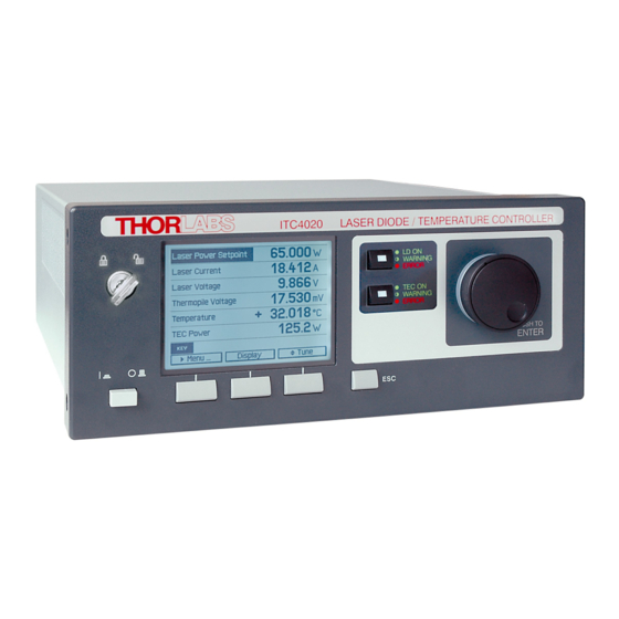
Laser Diode Current and
Temperature Controller
ITC4000 Series
Operation Manual
2018
Table of
Contents
Previous
Page
Next
Page
1
2
3
4
5
Advertisement
Table of Contents
Need help?
Do you have a question about the ITC4000 Series and is the answer not in the manual?
Ask a question
Questions and answers
Related Manuals for THORLABS ITC4000 Series
Controller Thorlabs ITC1 Series Operation Manual
Oem laser diode controller (46 pages)
Controller THORLABS ITC502 Operation Manual
Laser diode combi controller (123 pages)
Controller THORLABS ITC510 Operation Manual
Laser diode combi controller (123 pages)
Controller THORLABS LDC40 Series Programmer's Reference Manual
(97 pages)
Controller THORLABS ITC4001 Operation Manual
Laser diode current and temperature controller (105 pages)
Controller THORLABS ITC4005 Operation Manual
Laser diode current and temperature controller (105 pages)
Controller THORLABS ITC4020 Operation Manual
Laser diode current and temperature controller (105 pages)
Controller THORLABS IP500 User Manual
500 ma laser diode controller (16 pages)
Controller THORLABS IP250-BV User Manual
250 ma blue laser diode controller (16 pages)
Controller THORLABS IO-L-1050 User Manual
(12 pages)
Controller THORLABS MLC8 Series Operation Manual
Multi laser controller module for thorlabs blueline series pro8000 (-4) / pro800 (81 pages)
Controller Thorlabs SA201 Operating Manual
Spectrum analyzer controller (20 pages)
Controller THORLABS LDC200C series Operation Manual
Laser diode controller (38 pages)
Controller THORLABS TDC001 User Manual
Dc servo motor driver (56 pages)
Controller THORLABS SC10 Operating Manual
Shutter controller (12 pages)
Controller THORLABS MDT693B User Manual
Open-loop piezo controllers (32 pages)
This manual is also suitable for:
Itc4001
Itc4002qcl
Itc4005
Itc4005qcl
Itc4020
Table of Contents
Print
Rename the bookmark
Delete bookmark?
Delete from my manuals?
Login
Sign In
OR
Sign in with Facebook
Sign in with Google
Upload manual
Upload from disk
Upload from URL


Need help?
Do you have a question about the ITC4000 Series and is the answer not in the manual?
Questions and answers