Sign In
Upload
Manuals
Brands
Emerson Manuals
Measuring Instruments
Rosemount 8800DR
Emerson Rosemount 8800DR Manuals
Manuals and User Guides for Emerson Rosemount 8800DR. We have
2
Emerson Rosemount 8800DR manuals available for free PDF download: Reference Manual
Emerson Rosemount 8800DR Reference Manual (190 pages)
Vortex
Brand:
Emerson
| Category:
Measuring Instruments
| Size: 8 MB
Table of Contents
Table of Contents
4
Title Page
9
How to Use this Manual
10
Safety Messages
10
System Description
10
Process Variables
12
Primary Variable (PV)
12
Percent of Range
12
Analog Output
12
Process Variable Units
13
Volume Flow Units
13
Corrected Volumetric Flow Units
14
Velocity Flow
15
Velocity Flow Units
15
Velocity Measurement Base
15
Special Units
16
Base Flow Unit
16
Base Time Unit
16
Special Flow Unit
17
Conversion Number
17
Totalizer Control
17
Totalizer Config
18
Pulse Frequency
18
Shedding Frequency
18
Electronics Temperature
18
Electronics Temperature Units
18
Basic Setup
20
Tag
20
Long Tag
20
Process Configuration
20
Transmitter Mode
20
Fixed Process Temperature
21
Fixed Process Density
21
Base Process Density
21
Reference K-Factor
21
Flange Type
22
Pipe ID
22
Variable Mapping
23
Primary Variable
23
Secondary Variable
23
Third Variable
23
Fourth Variable
24
Process Variable Units
24
Analog Output
24
Primary Variable Upper Range Value (PV URV)
24
Damping
25
Optimize DSP (Digital Signal Processing)
25
Safety Messages
30
Commissioning
32
Flowmeter Sizing
32
Flowmeter Orientation
32
Vertical Installation
32
Horizontal Installation
33
Steam Installations
33
Upstream/Downstream Piping
34
Pressure and Temperature Transmitter Location
34
Wetted Material Selection
34
Environmental Considerations
35
Hazardous Locations
35
Hardware Configuration
35
Failure Mode Vs. Saturation Output Values
36
LCD Indicator Option
37
Meter Body Installation Tasks
37
Handling
37
Flow Direction
38
Gaskets
38
Flange Bolts
38
Wafer-Style Flowmeter Alignment and Mounting
40
Flanged-Style Flowmeter Mounting
42
Insert Integral Temperature Sensor (MTA Option Only)
42
Flowmeter Grounding
44
Electronics Considerations
44
High-Temperature Installations
45
Conduit Connections
45
High-Point Installation
45
Cable Gland
46
Grounding the Transmitter Case
46
Wiring Procedure
46
Power Supply
46
Remote Electronics
50
Cable Connections
51
Calibration
52
Software Configuration
52
Lcd Display
52
Installing the Indicator
54
Transient Protection
55
Installing the Transient Protector
56
Diagnostics/Service
58
Device Alerts
58
Minimum Electronics Temperature
58
Maximum Electronics Temperature
58
Reset Transmitter
59
Loop Test
59
Flow Simulation
59
Simulate Flow
60
Internal Flow Simulation
60
Analog Trim
60
Scaled Analog Trim
61
Shedding Frequency at URV
61
Advanced Functionality
61
Flow Sensor
61
Meter Body
62
Meter Factor
62
Alarm/Saturation Levels
62
Pulse Output
63
Scaled Volumetric
63
Scaled Velocity
64
Temperature Compensation
64
Temperature Compensated Steam
65
Temperature Compensated Liquids
65
User Defined
65
SMART Fluid Diagnostic
66
Analog Alarm
66
Alarm Latch
67
Optimize Gas Detection Filters
67
SMART Fluid Diagnostic Trial
67
Communications
68
Poll Address
69
Burst Mode
69
Burst Mode Configuration
69
Burst Option
70
Local Display
70
Signal Processing
70
Signal Strength
71
Manual Filter Adjust
71
Low Flow Cutoff
72
Trigger Level
72
Restore Default Filter
73
Flow Damping
73
Temperature Damping
73
Device Information
73
Write Protect
74
Revision Numbers
74
Software Revision
75
Hardware Revision
75
Change HART Revisions
75
Locate Device
75
Safety Messages
77
Troubleshooting Tables
77
Advanced Troubleshooting
78
Diagnostic Messages
78
Electronics Test Points
80
TP1-Test Point 1
82
Diagnostic Messages on LCD Display
84
Testing Procedures
85
Hardware Replacement
86
Replacing the Terminal Block in the Housing
86
Remove the Terminal Block
86
Install the Terminal Block
87
Replacing the Electronics Boards
87
Remove the Electronics Boards
88
Install the Electronics Boards
89
Replacing the Electronics Housing
89
Tools Needed
89
Remove the Electronics Housing
90
Install the Electronics Housing
90
Replacing the Sensor
91
Replacing the Sensor: Removable Support Tube
91
Cleaning the Sealing Surface
93
Sensor Installation
94
Remote Electronics Procedure
97
Disconnect the Coaxial Cable at the Meter
98
Detach the Meter Adapter
100
Attach the Meter Adapter
100
Connect the Coaxial Cable at the Meter Body
100
Coaxial Cable at the Electronics Housing
101
Remove the Coaxial Cable from the Electronics Housing
101
Attach the Coaxial Cable
102
Changing the Housing Orientation
102
Temperature Sensor Replacement (MTA Option Only)
103
Return of Material
104
Toll-Free Assistance Numbers
104
Aappendix A: Specifications and Reference Data
106
Specifications
106
Functional Specifications
106
Process Fluids
106
Pipe Schedules
106
Measurable Flow Rates
107
Analog Output Adjustment
108
Scalable Frequency Adjustment
108
Pressure Limits
109
Wafer Style Meter
109
Weld-End Style Meter
109
Power Consumption
110
Load Limitations (HART Analog)
110
Optional LCD Display
110
Enclosure Rating
110
Permanent Pressure Loss
111
Minimum Downstream Pressure (Liquids)
111
Failure Mode Alarm
112
Saturation Output Values
112
Response Time
112
Turn-On Time
112
Security Lockout
113
Output Testing
113
Humidity Limits
113
Over-Range Capability
113
Flow Calibration
114
Performance Specifications
126
Flow Accuracy
126
Process Temperature Accuracy
126
Mass Flow Accuracy for Temperature Compensated Steam Mass Flow
127
Mass Flow Accuracy for Temperature Compensated Liquid Mass Flow (Water)
127
Mass Flow Accuracy for Temperature Compensated Liquid Mass Flow (User-Defined)
127
Process Temperature Effect
127
Ambient Temperature Effect
128
Vibration Effect
128
Mounting Position Effect
128
EMI/RFI Effect
128
Magnetic-Field Interference
129
Physical Specifications
129
Electrical Connections
129
Process Connections
131
Temperature Limitations for Integral Mounting
131
Pipe Length Requirements
132
Flow Calibration Information
132
Dimensional Drawings
133
B.1 Overview
150
Product Certifications
150
B.2.1 Approved Manufacturing Locations
150
Flameproof Enclosure Ex D Protection Type in Accordance with IEC 60079-1, en 60079-1
150
Type N Protection Type in Accordance with IEC 60079-15
150
En60079-15
150
B.3 European Directive Information
150
B.4 ATEX Directive
150
European Pressure Equipment Directive (PED)
150
Hazardous Location Certifications
151
B.6.1 North American Certifications
151
B.6.2 European Certifications
151
B.6.3 International Iecex Certifications
153
Chinese Certifications (NEPSI)
154
Brazilian Certifications (INMETRO)
156
Eurasian Conformity (EAC)
156
Safety Messages
172
Electronics Verification
173
Electronics Verification Using Flow Simulation Mode
173
Fixed Flow Rate Simulation
173
Varying Flow Rate Simulation
173
Electronics Verification Using an External Frequency Generator
174
Calculating Output Variables with Known Input Frequency
176
Unit Conversion Table (User Units to GPS)
177
Examples
178
English Units
178
Units
181
Global Headquarters
189
Advertisement
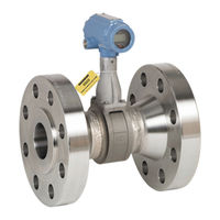
Emerson Rosemount 8800DR Reference Manual (192 pages)
Vortex Flowmeter with Foundation Fieldbus
Brand:
Emerson
| Category:
Measuring Instruments
| Size: 7 MB
Table of Contents
Table of Contents
3
Using this Manual
11
OUNDATION Fieldbus Technology
11
System Description
12
Overview
13
Safety Messages
13
User Interfaces
14
Commissioning
14
General Block Information
17
Modes of Operation
17
Block Instantiation
18
Resource Block
18
FEATURES and FEATURES_SEL
18
Max_Notify
19
Plantweb ™ Alarms
20
Transducer Block
23
Parameters
23
Xmtr_Mode
23
Process_Fluid
23
Reference K_FACTOR
23
Fixed_Proc_Temperature
23
Fixed_Proc_Density
23
Flange_Type
23
Pipe_Inside_Diameter
23
Damping
23
Filter_Auto_Adjust
24
Primary_Value_Range
24
Sensor_Range
24
Secondary_Value
24
Installation_Effects
24
Process_Density_Ratio
24
Meter_Display
24
Proc_Temp_Damp
25
Vel_Meas_Base
25
Tc_Failure_Mode
25
Lfc_Response
25
Calc_Proc_Density
25
Proc_Temp_Range
25
Elec_Temp_Range
25
Analog Input (AI) Function Block
26
Filtering
26
Low Cutoff
26
March
26
Process Alarms
27
Alarm Priority
27
Status Options
27
Advanced Features
28
Flow Simulation
28
Using Transducer Block Parameters
28
Configuration Software
29
Device Capabilities
29
Link Active Scheduler
29
Capabilities
30
Overview
31
Safety Messages
31
Environmental Considerations
32
Meter Body Installation Tasks
32
Handling
32
Flow Direction
33
Upstream/Downstream Piping
33
Flowmeter Orientation
34
High-Temperature Installations
36
Steam Installations
37
Conduit Connections
37
High-Point Installation
38
Hazardous Locations
38
Cable Gland
39
Gaskets
39
Meter Body Grounding
39
Flange Bolts
40
Wafer-Style Flowmeter Alignment and Mounting
41
Flanged-Style Flowmeter Mounting
43
Remote Electronics
44
Calibration
46
Electronics Considerations
46
Grounding the Transmitter Case
47
Commissioning Tag
48
Foundation ™ Fieldbus Transmitter Power Requirement
49
Power Conditioning
49
Field Wiring
49
Hardware Configuration
51
Simulate Enable
51
Transmitter Security
52
LCD Display Option
52
Transmitter Configuration
52
Overview
53
Quick Transducer Block Configuration Guide
53
Parameters and Descriptions
55
Block/Transducer Errors
62
Diagnostics
63
Alarm Detection
65
Status Handling
65
Error Conditions
66
Flow Units
66
Standard/Normal Flow Units
66
Transducer Block
67
Process Variables (PV)
67
Basic Setup
67
Flow Units
68
Sensor
69
Filtering
72
Display
73
Modes
73
Parameters and Descriptions
75
Definition
75
Block Errors
81
Modes
81
Alarm Detection
82
Status Handling
82
Vcr
82
Troubleshooting
82
Overview
75
Overview
83
Analog Input (AI) Function Block
83
Configure the AI Block
83
Overview
91
Safety Messages
91
Troubleshooting Tables
92
Advanced Troubleshooting
98
Tp1
99
Hardware Maintenance
100
Oundation
100
OUNDATION Fieldbus Electronics Boards
102
OUNDATION Fieldbus Electronics Housing
103
Replacing the Sensor
105
Replacing the Sensor: Removable and Integral Support Tubes
106
Remote Electronics Procedures
110
Coaxial Cable at the Electronics Housing
113
Oundation
114
Temperature Sensor Replacement (MTA Option Only)
115
Troubleshooting a Remote Mount Cable
116
Return of Material
118
A.1 Specifications
119
A.3 Performance Specifications
122
A.4 Physical Specifications
123
A.5 Dimensional Drawings
126
Product Certifications
143
B.1.1 Approved Manufacturing Locations
143
Flameproof Enclosure Ex D Protection Type in Accordance with IEC
143
60079-1, en 60079-1
143
En60079-15
143
B.2 European Directive Information
143
B.3 ATEX Directive
143
European Pressure Equipment Directive (PED)
143
Rosemount 8800D Vortex Flowmeter Line Size 40 MM to
143
Rosemount 8800D Vortex Flowmeter Line Size 15 MM and
143
B.5.1 North American Certifications
144
B.5.2 European Certifications
144
B.5.3 International Iecex Certifications
145
Chinese Certifications (NEPSI)
147
Brazilian Certifications (INMETRO)
148
EAC-Compliance with the Requirements of Technical Regulations
149
Of the Customs Union
149
C.1 Safety Messages
159
Safety Messages
159
C.2 Electronics Verification
160
Electronics Verification Using Internal Flow Simulation
161
Internal Flow Simulation-Fixed Flow Rate
161
Internal Flow Simulation-Varying Flow Rate
161
Electronics Verification Using an External Frequency Generator
162
Exiting Flow Simulation
162
Calculating Output Variables with Known Input Frequency
165
Electronics Verification
160
Examples
167
English Units
167
C.3 Examples
167
SI Units
169
C.3.2 si Units
169
March
170
Alerts
171
D.1 Alerts
171
Plantweb Alerts Overview
177
Alert Configuration NE107 and Plantweb
178
D.4 Alert Simulation
181
Alert Simulation
181
Advertisement
Related Products
Emerson 8800C
Emerson 8800A
Emerson Rosemount 8800D Series
Emerson Rosemount 8800DD
Emerson Rosemount 8800DW
Emerson 8700 Series
Emerson Rosemount 8600D Series
Emerson Rosemount 8600 Series
Emerson Rosemount 8782
Emerson Rosemount 8750WB
Emerson Categories
Controller
Control Unit
Transmitter
Measuring Instruments
Fan
More Emerson Manuals
Login
Sign In
OR
Sign in with Facebook
Sign in with Google
Upload manual
Upload from disk
Upload from URL