Emerson Rosemount 8732EM Quick Start Manual
Transmitter with
modbus protocol
Hide thumbs
Also See for Rosemount 8732EM:
- Reference manual (254 pages) ,
- Quick start manual (33 pages) ,
- Quick start manual (32 pages)
Advertisement
Quick Links
Download this manual
See also:
Reference Manual
Quick Start Guide
00825-0400-4444, Rev AC
November 2017
®
Rosemount
8732EM Transmitter with
Modbus Protocol
Advertisement

Related Manuals for Emerson Rosemount 8732EM


Summary of Contents for Emerson Rosemount 8732EM
- Page 1 Quick Start Guide 00825-0400-4444, Rev AC November 2017 ® Rosemount 8732EM Transmitter with Modbus Protocol...
- Page 2 • Completely remove all electrical connections from both sensor and transmitter prior to welding on the pipe. For maximum protection of the sensor, consider removing it from the pipeline. Rosemount 8732EM Transmitter with Modbus Protocol...
- Page 3 For additional installation information, configuration, maintenance, and ® troubleshooting, refer to the Rosemount 8732EM Transmitter with Modbus Protocol Reference Manual All user documentation can be found at www.emerson.com. For more contact information see Section 2.2. Return policy Emerson procedures must be followed when returning equipment. These...
- Page 4 +65 6 777 8211 Oman 800 70101 Thailand 001 800 441 6426 Qatar 431 0044 Malaysia 800 814 008 Kuwait 663 299 01 South Africa 800 991 390 Saudi Arabia 800 844 9564 800 0444 0684 Rosemount 8732EM Transmitter with Modbus Protocol...
- Page 5 November 2017 Quick Start Guide Pre-installation Before installing the transmitter, there are several pre-installation steps that should be completed to make the installation process easier: • Identify options and configurations that apply to your application • Set the hardware switches if necessary •...
- Page 6 Before making any electrical connections to the transmitter, consider national, local, and plant electrical installation requirements. Be sure to have the proper power supply, conduit, and other accessories necessary to comply with these standards. Rosemount 8732EM Transmitter with Modbus Protocol...
-
Page 7: Environmental Considerations
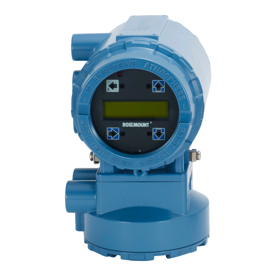
November 2017 Quick Start Guide The transmitter requires external power. Ensure access to a suitable power source. Table 3-2: Electrical data Rosemount 8732EM Flow Transmitter Power input AC power: 90–250VAC, 0.45A, 40VA Standard DC power: 12–42VDC, 1.2A, 15W Low power DC: 12–30VDC, 0.25A, 4W... - Page 8 C. Transmitter D. Fasteners (example configuration) 3. To enable correct orientation, the LOI can be rotated in 90 degree increments up to 180 degrees. Do not rotate more than 180 degrees in any one direction. Rosemount 8732EM Transmitter with Modbus Protocol...
- Page 9 November 2017 Quick Start Guide Wiring Conduit entries and connections Transmitter conduit entry ports can be ordered with ½"-14NPT or M20 female threaded connections. Conduit connections should be made in accordance with national, local, and plant electrical codes. Unused conduit entries should be sealed with the appropriate certified plugs.
- Page 10 Use only the factory supplied cable provided with the instrument. For replacement transmitters use the existing interconnecting cable from the original assembly. Replacement cables, if applicable, are available (see Figure 5-2). Rosemount 8732EM Transmitter with Modbus Protocol...
- Page 11 November 2017 Quick Start Guide Figure 5-2: Replacement interconnecting cables A. Socket module 08732-CSKT-0001 B. IMS cable 08732-CSKT-0004 Remote mount transmitters Cables kits are available as individual component cables or as a combination coil/electrode cable. Remote cables can be ordered directly using the kit numbers shown in Table 5-1,...
- Page 12 500–1000 feet (152–304 m). Equal length cable is required for each. For installations using the combination coil drive/electrode cable, see Figure 5-4. Combination cable lengths should be limited to less than 330 feet (100 m). Rosemount 8732EM Transmitter with Modbus Protocol...
- Page 13 November 2017 Quick Start Guide Figure 5-3: Individual component cables 17 18 19 A. Coil drive B. Electrode C. Twisted, stranded, insulated 14 AWG conductors D. Drain E. Overlapping foil shield F. Outer jacket G. Twisted, stranded, insulated 20 AWG conductors •...
- Page 14 5-5. Remove only enough insulation so that the exposed conductor fits completely under the terminal connection. Best practice is to limit the unshielded length (D) of each conductor to less than one inch. Excessive Rosemount 8732EM Transmitter with Modbus Protocol...
- Page 15 November 2017 Quick Start Guide removal of insulation may result in an unwanted electrical short to the transmitter housing or other terminal connections. Excessive unshielded length, or failure to connect cable shields properly, may also expose the unit to electrical noise, resulting in an unstable meter reading. Quick Start Guide...
- Page 16 Shock hazard! Potential shock hazard across remote junction box terminals 1 and 2 (40V). WARNING! Explosion hazard! Electrodes exposed to process. Use only compatible transmitter and approved installation practices. For process temperatures greater than 284°F (140°C), use a wire rated for 257°F (125°C). Rosemount 8732EM Transmitter with Modbus Protocol...
- Page 17 November 2017 Quick Start Guide Remote junction box terminal blocks Figure 5-6: Remote junction box views A. Sensor B. Transmitter Table 5-4: Sensor/transmitter wiring Wire color Sensor terminal Transmitter terminal Blue Shield 3 or Float Black Yellow White Note For hazardous locations, refer to the product reference manual. Quick Start Guide...
- Page 18 Quick Start Guide November 2017 Wiring sensor to transmitter Figure 5-7: Wiring 8732EM using component cable Rosemount 8732EM Transmitter with Modbus Protocol...
- Page 19 November 2017 Quick Start Guide Figure 5-8: Wiring 8732EM using combination cable Quick Start Guide...
- Page 20 Discrete I/O 1 (+) Discrete I/O 2 (–) Discrete I/O 2 (–) Discrete I/O 2 (+) Discrete I/O 2 (+) AC (Neutral)/L2 DC (–) AC L1 DC (+) Only available with ordering code AX. Rosemount 8732EM Transmitter with Modbus Protocol...
- Page 21 November 2017 Quick Start Guide Powering the transmitter The transmitter is available in three models. The AC powered transmitter is designed to be powered by 90–250VAC (50/60Hz). The DC powered transmitter is designed to be powered by 12–42VDC. The low power transmitter is designed to be powered by 12–30VDC.
- Page 22 Peak inrush is 42A at 42VDC supply, lasting approximately 1ms. Inrush for other supply voltages can be estimated with: Inrush (Amps) = Supply (Volts) / 1.0 Figure 5-12: DC current requirements A. Supply current (amps) B. Power supply (VDC) Rosemount 8732EM Transmitter with Modbus Protocol...
- Page 23 November 2017 Quick Start Guide Figure 5-13: Low power DC current requirements 0.25 0.15 0.05 A. Supply current (amps) B. Power supply (VDC) Supply wire requirements Use 10–18 AWG wire rated for the proper temperature of the application. For wire 10–14 AWG use lugs or other appropriate connectors. For connections in ambient temperatures above 122 °F (50 °C), use a wire rated for 194 °F (90 °C).
- Page 24 The Modbus output is a Modbus RTU signal using RS-485. Follow these cable recommendations for RS-485 interface (Modbus over serial line). Cable characteristics Type Shielded twisted pair cable with 2 conductors and a drain wire, or Ethernet cable of Cat 5/5e/6 Rosemount 8732EM Transmitter with Modbus Protocol...
- Page 25 November 2017 Quick Start Guide Conductor gauge 20–24 AWG for lengths up to 1000 feet 16–20 AWG for lengths up to 4000 feet Characteristic impedance 100–130 ohm Conductor-to-conductor <30 pF/ft capacitance Conductor-to-shield <60 pF/ft capacitance Voltage rating 300 V/600 V Recommended insulation PVC (<1000 ft) or PE (≥1000 ft) material...
- Page 26 Quick Start Guide November 2017 Figure 5-14: Modbus output wiring A. Modbus A/D0 B. Modbus B/D1 Rosemount 8732EM Transmitter with Modbus Protocol...
- Page 27 November 2017 Quick Start Guide Basic configuration Once the magnetic flowmeter is installed and power has been supplied, the transmitter must be configured through the basic setup. These parameters can be configured through either an LOI or a Modbus host. Configuration settings are saved in nonvolatile memory within the transmitter.
- Page 28 Tag (registers 68–71) Tag is the quickest and shortest way of identifying and distinguishing between transmitters. Transmitters can be tagged according to the requirements of your application. The tag may be up to eight characters long. Rosemount 8732EM Transmitter with Modbus Protocol...
- Page 29 November 2017 Quick Start Guide Flow units (register 61) The flow units variable specifies the format in which the flow rate will be displayed. Units should be selected to meet your particular metering needs. Table 6-1: Volume units Register value Units Barrels (31 gal)/sec Barrels (31 gal)/min...
- Page 30 0.10-in. (2 mm) 0.15-in. (4 mm) 0.25-in. (6 mm) 0.30-in. (8 mm) 0.50-in. (15 mm) 0.75-in. (18 mm) 1-in. (25 mm) 1.5-in. (40 mm) 2-in. (50 mm) 2.5-in. (65 mm) 3-in. (80 mm) (default) Rosemount 8732EM Transmitter with Modbus Protocol...
- Page 31 November 2017 Quick Start Guide Register value Line size 4-in. (100 mm) 5-in. (125 mm) 6-in. (150 mm) 8-in. (200 mm) 10-in. (250 mm) 12-in. (300 mm) 14-in. (350 mm) 16-in. (400 mm) 18-in. (450 mm) 20-in. (500 mm) 24-in. (600 mm) 28-in.
- Page 32 © Emerson Automation Solutions Japan 2017 Rosemount, Inc. All rights reserved. 1-2-5, Higashi Shinagawa The Emerson logo is a trademark and service mark Shinagawa-ku of Emerson Electric Co. Rosemount, 8600, 8700, Tokyo 140-0002 Japan 8800 marks are marks of one of the Emerson T +81 3 5769-6803 Automation Solutions family of companies.
Need help?
Do you have a question about the Rosemount 8732EM and is the answer not in the manual?
Questions and answers