Sign In
Upload
Download
Table of Contents
Contents
Add to my manuals
Delete from my manuals
Share
URL of this page:
HTML Link:
Bookmark this page
Add
Manual will be automatically added to "My Manuals"
Print this page
×
Bookmark added
×
Added to my manuals
Manuals
Brands
Emerson Manuals
Measuring Instruments
Rosemount 8742C
Reference manual
Emerson Rosemount 8742C Reference Manual
Magnetic flowmeter transmitter with foundation fieldbus and magnetic flowmeter flowtube
Hide thumbs
1
2
3
4
Table Of Contents
5
6
7
8
9
10
11
12
13
14
15
16
17
18
19
20
21
22
23
24
25
26
27
28
29
30
31
32
33
34
35
36
37
38
39
40
41
42
43
44
45
46
47
48
49
50
51
52
53
54
55
56
57
58
59
60
61
62
63
64
65
66
67
68
69
70
71
72
73
74
75
76
77
78
79
80
81
82
83
84
85
86
87
88
89
90
91
92
93
94
95
96
97
98
99
100
101
102
103
104
105
106
107
108
109
110
111
112
113
114
115
116
117
118
119
120
121
122
123
124
125
126
127
128
129
130
131
132
133
134
135
136
page
of
136
Go
/
136
Contents
Table of Contents
Troubleshooting
Bookmarks
Table of Contents
Table of Contents
System Description
Section 1 Introduction
Safety Messages
Return of Materials
Safety Information
Transmitter Symbols
Pre-Installation
Identify Options and Configurations
Hardware Switches
Simulate Enable
Transmitter Security
Changing Hardware Switch Settings
Rotate Transmitter Housing
Wiring
Conduit Ports and Connections
Conduit Connections
Conduit Cables
Transmitter Coil Input
Installation Category
Overcurrent Protection
Transmitter Communication Input
Power Conditioning
Field Wiring
Transmitter Wiring Connection
Transmitter to Flowtube Wiring
Flowtube to Remote Mount Transmitter Connections
Flowtube to Integral Mount Transmitter Connections
Safety Messages
Flowtube Handling
Flowtube Mounting
Upstream/Downstream
Piping
Flowtube Orientation
Flow Direction
Installation (Flanged Flowtube)
Gaskets
Flange Bolts
Installation (Wafer Flowtube)
Gaskets
Flange Bolts
Installation (Sanitary Flowtube)
Gaskets
Alignment and Bolting
Grounding
Process Leak Protection (Optional)
Standard Housing Configuration
Relief Valves
Process Leak Containment
Calibration
Quick Start-Up
Flowtube Calibration Number
Assigning Device Tag and Node Address
AI Block
Arithmetic Block
Integrator
PID Block
Configuring Links and Scheduling Block Execution
Advanced Applications
Cascade Control
Resource Block
Plantweb ™ Alarms
Max_Notify
Safety Information
Software Operation
Local Display Configuration
Calibration
Electronics Trim
Auto Zero Trim
Configuring the Advanced Diagnostics and Empty Pipe
Learning Empty Pipe
Diagnostics
Diagnostic Information
Diagnostic Counter
Hardware Maintenance
Replacing the FOUNDATION
Replacing the FOUNDATION
Step 1: Function Block Errors
Step 2: Diagnostic Messages
Step 3: Wiring Errors
Step 4: Process Noise
Step 5: Installed Flowtube Tests
Step 6: Uninstalled Flowtube Tests
Rosemount 8742C Transmitter Specifications
Functional Specifications
Foundation Fieldbus Specifications
Performance Specifications
Physical Specifications
APPENDIX A Rosemount 8705 and 8707 Flowtubes Specifications
Functional Specifications
Performance Specifications
Physical Specifications
Rosemount 8711 Wafer Flowtube Specifications
Functional Specifications
Performance Specifications
Physical Specifications
Rosemount 8714D Specifications
Functional Specifications
Performance Specifications
Physical Specifications
Dimensional Drawings
Ordering Information
Rosemount 8705
Rosemount 8707
Rosemount 8711
Rosemount 8714
Approved Manufacturing Locations
APPENDIX B European Directive Information
ATEX Directive
European Pressure Equipment Directive (PED) (97/23/EC
Electro Magnetic Compatibility (EMC) (89/336/EEC
Low Voltage Directive (93/68/EEC
Other Important Guidelines
Hazardous Location Certifications
Transmitter Approval Information
Flowtube Approval Information
Definition
Appendix C
Resource Block Errors
Alarm Detection
Status Handling
Vcr
Modes
Troubleshooting
Definition
Appendix D
Flow-Specific Block Configuration Values
Transducer Block Errors
Transducer Block Diagnostics
Modes
Alarm Detection
Status Handling
Troubleshooting
Appendix E
Safety Messages
Remove the Electrode Assembly
Replace the Electrode Assembly
Advertisement
Quick Links
1
Rosemount 8742C Transmitter Specifications
Download this manual
Reference Manual
00809-0100-4793, Rev CA
August 2004
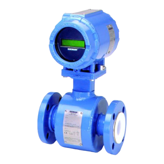
Rosemount 8742C Magnetic Flowmeter
™
Transmitter with F
Fieldbus and
OUNDATION
8700 Series Magnetic Flowmeter Flowtube
P r o d u c t D i s c o n t i n u e d
www.rosemount.com
Table of
Contents
Previous
Page
Next
Page
1
2
3
4
5
Advertisement
Table of Contents
Troubleshooting
Alarm Detection
122
Status Handling
128
Need help?
Do you have a question about the Rosemount 8742C and is the answer not in the manual?
Ask a question
Questions and answers
Related Manuals for Emerson Rosemount 8742C
Measuring Instruments Emerson Rosemount 8750W Quick Start Manual
Magnetic flowmeter system for utility, water, and wastewater applications (52 pages)
Measuring Instruments Emerson Rosemount 8750W Reference Manual
Magnetic flowmeter platform for utility, water, and wastewater applications (264 pages)
Measuring Instruments Emerson 8700 Series Reference Manual
Magnetic flowmeter transmitter with foundation fieldbus and magnetic flowmeter flowtube (136 pages)
Measuring Instruments Emerson Rosemount 8732EM Quick Start Manual
Transmitter with modbus protocol (32 pages)
Measuring Instruments Emerson Rosemount 8750WA Quick Installation Manual
Magnetic flowmeter system transmitter and sensor (38 pages)
Measuring Instruments Emerson Rosemount 8782 Reference Manual
Slurry magnetic flow meter transmitter with hart protocol (174 pages)
Measuring Instruments Emerson Rosemount 8750WB Quick Start Manual
Magnetic flowmeter system (44 pages)
Measuring Instruments Emerson Rosemount 8732 Quick Installation Manual
Magnetic flowmeter system (39 pages)
Measuring Instruments Emerson 8800C Product Manual
Smart vortex flowmeter (160 pages)
Measuring Instruments Emerson Rosemount 8800D Series Quick Start Manual
Vortex flowmeter (40 pages)
Measuring Instruments Emerson Rosemount 8800D Series Safety Manual
Vortex flowmeter safety manual for safety instrumented systems (30 pages)
Measuring Instruments Emerson Rosemount 8800D Series Reference Manual
Vortex flowmeter (188 pages)
Measuring Instruments Emerson Rosemount 8800D Series Reference Manual
Vortex flowmeter with foundation fieldbus (192 pages)
Measuring Instruments Emerson Rosemount 8800D Technical Notes
Calibration verification practices vortex flowmeters (hart protocol) (12 pages)
Measuring Instruments Emerson Rosemount 8800D Series Reference Manual
Vortex flow meter with modbus protoco (132 pages)
Measuring Instruments Emerson Rosemount 8600D Series Reference Manual
Vortex flowmeter (144 pages)
This manual is also suitable for:
8700 series
Table of Contents
Print
Rename the bookmark
Delete bookmark?
Delete from my manuals?
Login
Sign In
OR
Sign in with Facebook
Sign in with Google
Upload manual
Upload from disk
Upload from URL


Need help?
Do you have a question about the Rosemount 8742C and is the answer not in the manual?
Questions and answers