Emerson Rosemount 8600D Series Reference Manual
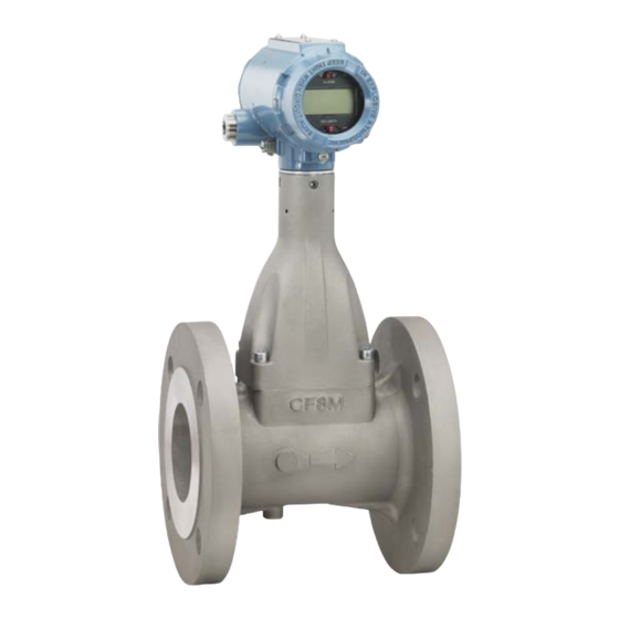
Vortex flowmeter
Hide thumbs
Also See for Rosemount 8600D Series:
- Quick start manual (41 pages) ,
- Reference manual (130 pages)

Related Manuals for Emerson Rosemount 8600D Series


Summary of Contents for Emerson Rosemount 8600D Series
- Page 1 Reference Manual 00809-0100-4860, Rev BC January 2013 Rosemount 8600D Series Vortex Flowmeter Get other manuals https://www.bkmanuals.com...
- Page 2 Reference Manual 00809-0100-4860, Rev BC January 2013 www.emersonprocess.com/rosemount Get other manuals https://www.bkmanuals.com...
- Page 3 North American Response Center Equipment service needs. 1-800-654-7768 (24 hours—includes Canada) Outside of the United States, contact your local Emerson Process Management representative. The products described in this document are NOT designed for nuclear-qualified applications. Using non-nuclear qualified products in applications that require nuclear-qualified hardware or products may cause inaccurate readings.
- Page 4 Reference Manual Title Page 00809-0100-4860, Rev BC January 2013 Get other manuals https://www.bkmanuals.com...
-
Page 5: Table Of Contents
Reference Manual Table of Contents 00809-0100-4860, Rev BC January 2013 Contents 1Section 1: Introduction How to use this manual..........1 Safety messages . - Page 6 Reference Manual Table of Contents 00809-0100-4860, Rev BC January 2013 2.8.1 Installing the Transient Protector ........27 3Section 3: Configuration Review .
- Page 7 Reference Manual Table of Contents 00809-0100-4860, Rev BC January 2013 5Section 5: Troubleshooting Safety messages ............67 Troubleshooting tables .
- Page 8 Reference Manual Table of Contents 00809-0100-4860, Rev BC January 2013 CAppendix C: Electronics verification Safety messages ........... . . 119 Electronics verification .
-
Page 9: 1Section 1: Introduction
Reference Manual Section 1: Introduction 00809-0100-4860, Rev BC January 2013 Section 1 Introduction How to use this manual ........... page 1 Safety messages . -
Page 10: Safety Messages
Reference Manual Section 1: Introduction 00809-0100-4860, Rev BC January 2013 Safety messages Procedures and instructions in this manual may require special precautions to ensure the safety of the personnel performing the operations. Refer to the safety messages, listed at the beginning of each section, before performing any operations. -
Page 11: Safety Messages
Reference Manual Section 2: Installation 00809-0100-4860, Rev BC January 2013 Section 2 Installation Safety messages ............page 3 Commissioning . - Page 12 Reference Manual Section 2: Installation 00809-0100-4860, Rev BC January 2013 Figure 2-1. Installation Flowchart Bench START HERE Commissioning? FIELD INSTALL Review CONFIGURE Configuration Mount Flowmeter Configuration Process Config • Transmitter Mode • Process Fluid • Fixed Process Temp. Mount • Dens/Dens Ratio Conduit Go to -Density Ratio...
-
Page 13: Commissioning
Reference Manual Section 2: Installation 00809-0100-4860, Rev BC January 2013 Commissioning Commission the Rosemount 8600D before putting it into operation. This ensures proper configuration and operation of the meter. It also enables you to check hardware settings, test the flowmeter electronics, verify flowmeter configuration data, and check output variables. Any problems can be corrected –... - Page 14 Reference Manual Section 2: Installation 00809-0100-4860, Rev BC January 2013 Horizontal installation For horizontal installation, the preferred orientation is to have the electronics installed to the side of the pipe. In liquid applications, this ensures any entrapped air or solids do not strike the shedding bar and disrupt the shedding frequency.
-
Page 15: Wetted Material Selection
Reference Manual Section 2: Installation 00809-0100-4860, Rev BC January 2013 Upstream/Downstream piping The vortex meter may be installed with a minimum of ten diameters (D) of straight pipe length upstream and five diameters (D) of straight pipe length downstream. Rated accuracy is based on the number of pipe diameter from an upstream disturbance. No K-factor correction is required if the meter is installed with 35 D upstream and 5 D downstream. -
Page 16: Hazardous Locations
Reference Manual Section 2: Installation 00809-0100-4860, Rev BC January 2013 Although the signal conditioning functions reduce susceptibility to extraneous noise, some environments are more suitable than others. Avoid placing the flowmeter or its wiring close to devices that produce high intensity electromagnetic and electrostatic fields. Such devices include electric welding equipment, large electric motors and transformers, and communication transmitters. -
Page 17: Failure Mode Vs. Saturation Output Values
Reference Manual Section 2: Installation 00809-0100-4860, Rev BC January 2013 Alarm As part of normal operations, the Rosemount 8600D continuously runs a self-diagnostic routine. If the routine detects an internal failure in the electronics, flowmeter output is driven to a low or high alarm level, depending on the position of the failure mode jumper. The failure mode jumper is labeled ALARM and is set at the factory per the CDS (Configuration Data Sheet);... -
Page 18: Lcd Indicator Option
Reference Manual Section 2: Installation 00809-0100-4860, Rev BC January 2013 2.4.2 LCD indicator option If your electronics are equipped with the LCD indicator (Option M5), the ALARM and SECURITY jumpers are located on the face of the indicator as shown in Figure 2-6. -
Page 19: Meter Body Installation Tasks
Reference Manual Section 2: Installation 00809-0100-4860, Rev BC January 2013 Meter body installation tasks The installation tasks include detailed mechanical and electrical installation procedures. 2.5.1 Handling Handle all parts carefully to prevent damage. Whenever possible, transport the system to the installation site in the original shipping containers. -
Page 20: Flange Bolts
Reference Manual Section 2: Installation 00809-0100-4860, Rev BC January 2013 2.5.4 Flange bolts Install the Rosemount 8600D Flowmeter between two conventional pipe flanges, as shown in Figure 2-7 on page Figure 2-7. Flanged-Style Flowmeter Installation Installation Bolts and Nuts (Supplied by Customer) Flow Gaskets (Supplied by Customer) -
Page 21: Flanged-Style Flowmeter Mounting
Reference Manual Section 2: Installation 00809-0100-4860, Rev BC January 2013 2.5.5 Flanged-style flowmeter mounting Physical mounting of a flanged-style flowmeter is similar to installing a typical section of pipe. Conventional tools, equipment, and accessories (such as bolts and gaskets) are required. Tighten the nuts following the sequence shown in Figure 2-8. -
Page 22: Electronics Considerations
Reference Manual Section 2: Installation 00809-0100-4860, Rev BC January 2013 Electronics considerations Both integral and remote mounted electronics require input power at the electronics. For remote mount installations, mount the electronics against a flat surface or on a pipe that is up to two inches (50 mm) in diameter. Remote mounting hardware includes an L bracket that is stainless steel and one stainless steel u-bolt. -
Page 23: Cable Gland
Reference Manual Section 2: Installation 00809-0100-4860, Rev BC January 2013 Figure 2-9. Proper Conduit Installation with Rosemount 8600D Conduit Line Conduit Line 2.6.4 Cable gland If you are using cable glands instead of conduit, follow the cable gland manufacturer’s instructions for preparation and make the connections in a conventional manner in accordance with local or plant electrical codes. -
Page 24: Wiring Procedure
Reference Manual Section 2: Installation 00809-0100-4860, Rev BC January 2013 2.6.6 Wiring procedure The signal terminals are located in a compartment of the electronics housing separate from the flowmeter electronics. Connections for a HART-based communicator and a current test connection are above the signal terminals. Figure 2-10 illustrates the power supply load limitations for the flowmeter. - Page 25 Reference Manual Section 2: Installation 00809-0100-4860, Rev BC January 2013 Figure 2-10. Power Supply Load Limitations Note in the equation above refers to the total loop load resistance. Technically, the total loop(max) loop load resistance is the sum of the loop load resistor, signal wiring resistance, and if applicable, any intrinsic safety barriers.
- Page 26 Reference Manual Section 2: Installation 00809-0100-4860, Rev BC January 2013 Note If a Smart Wireless THUM™ Adapter is being used with the Rosemount 8600 flowmeter to exchange information via the WirelessHART protocol, an additional 2.5 Vdc is dropped in the connected loop.
- Page 27 Reference Manual Section 2: Installation 00809-0100-4860, Rev BC January 2013 Pulse output Note Remember when using the pulse output, all power to the electronics is still supplied over the 4–20 mA signal wiring. The flowmeter provides an isolated transistor switch-closure frequency output signal proportional to flow, as shown in Figure 2-11.
- Page 28 Reference Manual Section 2: Installation 00809-0100-4860, Rev BC January 2013 Note When using pulse output, be sure to follow these precautions: Shielded twisted pair is required when the pulse output and 4–20 mA output are run in the same conduit or cable trays. Shielded wire will also reduce false triggering caused by noise pickup.
-
Page 29: Remote Electronics
Reference Manual Section 2: Installation 00809-0100-4860, Rev BC January 2013 Figure 2-13. 4-20 mA Wiring 250 Test Ammeter Figure 2-14. 4–20 mA and Pulse Wiring with Electronic Totalizer/ Counter Pulse Counter 250 – Test Ammeter 2.6.7 Remote electronics If you order one of the remote electronics options (options R10, R20, R30, R33, R50, or RXX), the flowmeter assembly will be shipped in two parts: The meter body with an adapter installed in the bracket and an interconnecting coaxial... - Page 30 Reference Manual Section 2: Installation 00809-0100-4860, Rev BC January 2013 Mounting Mount the meter body in the process flow line as described earlier in this section. Mount the bracket and electronics housing in the desired location. The housing can be repositioned on the bracket to facilitate field wiring and conduit routing.
-
Page 31: Calibration
Reference Manual Section 2: Installation 00809-0100-4860, Rev BC January 2013 If you plan to run the coaxial cable in conduit, carefully cut the conduit to the desired length to provide for proper assembly at the housing. A junction box may be placed in the conduit run to provide a space for extra coaxial cable length. - Page 32 Reference Manual Section 2: Installation 00809-0100-4860, Rev BC January 2013 the indicator. Figure 2-16 shows the flowmeter fitted with the LCD indicator and extended cover. Figure 2-16. Rosemount 8600D with Optional Indicator Electronics Board The indicator features an eight-character (and five alphanumeric) liquid crystal display that gives a direct reading of the digital signal from the microprocessor.
-
Page 33: Installing The Indicator
Reference Manual Section 2: Installation 00809-0100-4860, Rev BC January 2013 Figure 2-17 shows the indicator display with all segments lit. Figure 2-17. Optional Liquid Crystal Display A HART-based communicator can be used to change the engineering units of the parameters displayed on the indicator. -
Page 34: Transient Protection
Reference Manual Section 2: Installation 00809-0100-4860, Rev BC January 2013 Note The circuit board is electrostatically sensitive. Be sure to observe handling precautions for static-sensitive components. Insert the mounting screws into the LCD indicator. Remove the two jumpers on the circuit board that coincide with the Alarm and the Security settings. -
Page 35: Installing The Transient Protector
Reference Manual Section 2: Installation 00809-0100-4860, Rev BC January 2013 2.8.1 Installing the Transient Protector For flowmeters ordered with the transient protector option (T1), the protector is shipped installed. When purchased separately from the Rosemount 8600D, you must install the protector on a Rosemount 8600D flowmeter using a small instrument screwdriver, a pliers, and the transient protection kit. - Page 36 Reference Manual Section 2: Installation 00809-0100-4860, Rev BC January 2013 Installation Get other manuals https://www.bkmanuals.com...
-
Page 37: 3Section 3: Configuration
Reference Manual Section 3: Configuration 00809-0100-4860, Rev BC January 2013 Section 3 Configuration Review ..............page 29 Process variables . -
Page 38: Pv% Of Range
Reference Manual Section 3: Configuration 00809-0100-4860, Rev BC January 2013 3.2.2 PV% of range Field Comm. 1, 1, 2 Percent of Range — The primary variable as a percentage of range provides a gauge as to where the current measurement of the meter is within the configured range of the meter. For example, the range may be defined as 0 gal/min to 20 gal/min. - Page 39 Reference Manual Section 3: Configuration 00809-0100-4860, Rev BC January 2013 Barrels per day BBL/D bbl/d Imperial Gallons per second IGAL/S Impgal/s Imperial Gallons per minute IGAL/M Impgal/min Imperial Gallons per hour IGAL/H Impgal/h Imperial Gallons per day IGAL/D Impgal/d Liters per second Liters per minute L/MIN L/min...
- Page 40 Reference Manual Section 3: Configuration 00809-0100-4860, Rev BC January 2013 Rosemount 8600D to display flow in barrels per minute instead of gallons per minute, and one barrel is equal to 31.0 gallons. Base volume unit: gal Base time unit: min ...
- Page 41 Reference Manual Section 3: Configuration 00809-0100-4860, Rev BC January 2013 For example, if you are converting from gallons to barrels and there are 31 gallons in a barrel, the conversion factor is 31. The conversion equation is as follows (where barrels is the new volume unit): 1 gallon = 0.032258 bbl.
- Page 42 Reference Manual Section 3: Configuration 00809-0100-4860, Rev BC January 2013 Velocity flow Field Comm. 1, 1, 4, 3, 1 Displays the current velocity flow value and units. Velocity units Field Comm. 1, 1, 4, 3, 2 Allows the user to select the velocity units from the available list. ft/s Velocity measured base Field Comm.
- Page 43 Reference Manual Section 3: Configuration 00809-0100-4860, Rev BC January 2013 Totalizer config Field Comm. 1, 1, 4, 4, 5 Totalizer Config — Used to configure the flow parameter (volume, mass, velocity) that will be totalled. Note The totalizer value is saved in the non-volatile memory of the electronics every three seconds. Should power to the transmitter be interrupted, the totalizer value will start at the last saved value when the power is re-applied.
- Page 44 Reference Manual Section 3: Configuration 00809-0100-4860, Rev BC January 2013 Calculated process density Field Comm. 1, 1, 4, 8 Allows users to view the calculated process density value when the vortex is configured for temperature compensated steam applications. Also allows the user to configure the calculated density units.
-
Page 45: Basic Setup
Reference Manual Section 3: Configuration 00809-0100-4860, Rev BC January 2013 T/C failure mode Field Comm. 1, 1, 4, 9, 3 Allows the user to configure the temperature sensor failure mode. In the event that the thermocouple sensor fails, the vortex can go either into an alarm output mode, or continue to operate normally using the Fixed Process Temperature value. -
Page 46: Tag
Reference Manual Section 3: Configuration 00809-0100-4860, Rev BC January 2013 3.2.6 Field Comm. 1, 3, 1 Tag is the quickest way to identify and distinguish between flowmeters. Flowmeters can be tagged according to the requirements of your application. The tag may be up to eight characters long. - Page 47 Reference Manual Section 3: Configuration 00809-0100-4860, Rev BC January 2013 Density/Density ratio Field Comm. 1, 3, 2, 4 When configuring a meter for mass flow units, a density value needs to be entered. When configuring a meter for Standard and Normal Volumetric flow units a density ratio will be required.
- Page 48 Reference Manual Section 3: Configuration 00809-0100-4860, Rev BC January 2013 Operating conditions Field Comm. 1, 3, 2, 4, 1, 2, 1 = absolute temperature at actual (flowing) conditions in degrees Rankine or Kelvin. (The transmitter will convert from degrees Fahrenheit or degrees Celsius to degrees Rankine or Kelvin respectively.) = absolute pressure at actual (flowing) conditions psia or KPa absolute.
-
Page 49: Reference K-Factor
1, 3, 3 The reference K-factor is a factory calibration number relating the flow through the meter to the shedding frequency measured by the electronics. Every 8600 meter manufactured by Emerson is run through a water calibration to determine this value. -
Page 50: 12Pv Units
Reference Manual Section 3: Configuration 00809-0100-4860, Rev BC January 2013 Primary Variable (PV) Field Comm. 1, 3, 6, 1 Selections for this Variable are Mass Flow, Volumetric Flow, Velocity Flow, and Process Temperature. The Primary Variable is the variable mapped to the analog output. Secondary Variable (SV) Field Comm. -
Page 51: 14Pv Damping
Reference Manual Section 3: Configuration 00809-0100-4860, Rev BC January 2013 Primary Variable Lower Range Value (PV LRV) Field Comm. 1, 3, 8, 2 This is the 4 mA set point for the meter, and is typically set to 0 when the PV is a Flow Variable. 3.2.14 PV damping Field Comm. - Page 52 Reference Manual Section 3: Configuration 00809-0100-4860, Rev BC January 2013 Figure 3-1. Field Communicator Menu Tree for the Rosemount 8600D 1. Process 1. PV 1. Volumetric Flow 1. Volume Flow 1. Base Volume Unit 2. PV % Range 2. Mass Flow 2.
- Page 53 Reference Manual Section 3: Configuration 00809-0100-4860, Rev BC January 2013 Table 3-2. Field Communicator Fast Key Sequences for the Rosemount 8600D Function Fast Keys Function Fast Keys Alarm Jumper 1, 4, 2, 1, 3 Poll Address 1, 4, 2, 3, 1 Process Fluid Type 1, 3, 2, 2 Analog Output (Config)
- Page 54 Reference Manual Section 3: Configuration 00809-0100-4860, Rev BC January 2013 Configuration Get other manuals https://www.bkmanuals.com...
-
Page 55: 4Section 4: Operation
Reference Manual Section 4: Operation 00809-0100-4860, Rev BC January 2013 Section 4 Operation Diagnostics/service ............page 47 Advanced functionality . -
Page 56: Loop Test
Reference Manual Section 4: Operation 00809-0100-4860, Rev BC January 2013 Density test calc Field Comm. 1, 2, 1, 3 Allows for the test of the density calculation for saturated steam. The vortex meter will calculate the associated steam density at a user entered temperature value. Process Fluid must be set to Tcomp Sat Steam in order to run this test. -
Page 57: Pulse Output Test
Reference Manual Section 4: Operation 00809-0100-4860, Rev BC January 2013 4.1.3 Pulse output test Field Comm. 1, 2, 3 Pulse Output Test is a fixed frequency mode test that checks the integrity of the pulse loop. It tests that all connections are good and that the pulse output is running on the loop. 4.1.4 Flow simulation Field Comm. -
Page 58: D/A Trim
Reference Manual Section 4: Operation 00809-0100-4860, Rev BC January 2013 Simulate flow external Field Comm. 1, 2, 4, 3, 2 Simulate flow external allows you to disconnect the sensor electronically so an external frequency source can be used to test and verify the electronics. Enable normal flow Field Comm. -
Page 59: Shed Freq At Urv
Reference Manual Section 4: Operation 00809-0100-4860, Rev BC January 2013 Once your scaled trim points have been entered as 2 and 10, you can now calibrate your flowmeter by entering voltage measurements directly from the voltmeter. 4.1.7 Shed freq at URV Field Comm. - Page 60 Reference Manual Section 4: Operation 00809-0100-4860, Rev BC January 2013 Mating pipe I.D. Field Comm. 1, 4, 1, 2 The inside diameter of the pipe adjacent to the flow meter can cause entrance effects that may alter flowmeter readings. The exact inside diameter of the pipe must be specified to correct for these effects.
-
Page 61: Configure Outputs
Reference Manual Section 4: Operation 00809-0100-4860, Rev BC January 2013 4.3.2 Configure outputs Field Comm. 1, 4, 2 The Rosemount 8600D is digitally adjusted at the factory using precision equipment to ensure accuracy. You should be able to install and operate the flowmeter without a D/A Trim. Analog output Field Comm. - Page 62 Reference Manual Section 4: Operation 00809-0100-4860, Rev BC January 2013 Alarm level select Field Comm. 1, 4, 2, 1, 5 Select the Alarm level of the transmitter. Either Rosemount standard or NAMUR compliant. Alarm / sat levels Field Comm. 1, 4, 2, 1, 6 Displays Alarm and Saturation mA output levels.
- Page 63 Reference Manual Section 4: Operation 00809-0100-4860, Rev BC January 2013 Pulse output Field Comm. 1, 4, 2, 2, 1 The Rosemount 8600D comes with an optional pulse output option (P). This enables the flowmeter to output the pulse rate to an external control system, totalizer, or other device. If the flowmeter was ordered with the pulse mode option, it may be configured for either pulse scaling (based on rate or unit) or shedding frequency output.
- Page 64 Reference Manual Section 4: Operation 00809-0100-4860, Rev BC January 2013 Scaled velocity Field Comm. 1, 4, 2, 2, 1, 4 This mode allows you to configure the pulse output based on a velocity Flow Rate. Pulse scaling rate Field Comm. 1, 4, 2, 2, 1, 4, 1 Allows the user to set a certain velocity flow rate to a desired frequency.
- Page 65 Reference Manual Section 4: Operation 00809-0100-4860, Rev BC January 2013 Pulse output test Field Comm. 1, 4, 2, 2, 2 Pulse Output Test is a fixed frequency mode test that checks the integrity of the pulse loop. It tests that all connections are good and that pulse output is running on the loop. HART output Field Comm.
- Page 66 Reference Manual Section 4: Operation 00809-0100-4860, Rev BC January 2013 Poll address Field Comm. 1, 4, 2, 3, 1 Poll Address enables you to set the poll address for a multi-dropped meter. The poll address is used to identify each meter on the multi-drop line. Follow the on-screen instructions to set the address at a number from 1 to 15.
- Page 67 Reference Manual Section 4: Operation 00809-0100-4860, Rev BC January 2013 Burst option Field Comm. 1, 4, 2, 3, 5 Burst Option enables you to select the variables to broadcast over the burst transmitter. Choose one of the following options: PV–Selects the process variable for broadcast over the burst transmitter. Percent Range/Current–Selects the process variable as percent of range and analog output variables for broadcast over the burst transmitter.
-
Page 68: Signal Processing
Reference Manual Section 4: Operation 00809-0100-4860, Rev BC January 2013 XMTR variable slot 4 Field Comm. 1, 4, 2, 3, 6, 4 User selected Burst Variable 4. Local display Field Comm. 1, 4, 2, 4 The Local Display function on the Rosemount 8600D allows you to select which variables are shown on the optional (M5) local display. - Page 69 Reference Manual Section 4: Operation 00809-0100-4860, Rev BC January 2013 If one or more of these conditions exist, and you have checked other potential sources (K-factor, service type, lower and upper range values, 4–20mA trim, pulse scaling factor, process temperature, pipe ID), refer to Section 5: Troubleshooting.
- Page 70 Reference Manual Section 4: Operation 00809-0100-4860, Rev BC January 2013 Manual filter adjust Field Comm. 1, 4, 3, 2 Manual Filter Adjust allows you to manually adjust the following settings: Low Flow Cutoff, Low Pass Filter, and Trigger Level, while monitoring flow and or sig/tr. Primary Variable (PV) Field Comm.
- Page 71 Reference Manual Section 4: Operation 00809-0100-4860, Rev BC January 2013 The Low Pass Filter corner frequency variable offers two modes for adjustment: Increase filtering Increase sensitivity Trigger level Field Comm. 1, 4, 3, 2, 5 Trigger Level is configured to reject noise within the flow range while allowing normal amplitude variation of the vortex signal.
-
Page 72: Device Information
Reference Manual Section 4: Operation 00809-0100-4860, Rev BC January 2013 Temperature damping Field Comm. 1, 4, 3, 4, 3 The default damping value is 2.0 seconds. Temperature Damping can be reset to any value between 0.4 and 32 seconds. LFC response Field Comm. - Page 73 Reference Manual Section 4: Operation 00809-0100-4860, Rev BC January 2013 Date Field Comm. 1, 4, 4, 5 Date is a user-defined variable that provides a place to save a date, typically used to store the last date that the transmitter configuration was changed. Write protect Field Comm.
- Page 74 Reference Manual Section 4: Operation 00809-0100-4860, Rev BC January 2013 Hardware rev Field Comm. 1, 4, 4, 8, 4 Hardware Rev – Designates the revision level for the Rosemount 8600D hardware. Final assembly number Field Comm. 1, 4, 4, 8, 5 Final Assembly Number –...
-
Page 75: Safety Messages
Reference Manual Section 5: Troubleshooting 00809-0100-4860, Rev BC January 2013 Section 5 Troubleshooting Safety messages ............page 67 Troubleshooting tables . -
Page 76: 5Section 5: Troubleshooting
Reference Manual Section 5: Troubleshooting 00809-0100-4860, Rev BC January 2013 Explosions could result in death or serious injury: Do not remove the transmitter cover or thermocouple (MTA option only) from the electronics housing in explosive atmospheres when the circuit is alive. Before connecting a HART-based communicator in an explosive atmosphere, make ... -
Page 77: Advanced Troubleshooting
Reference Manual Section 5: Troubleshooting 00809-0100-4860, Rev BC January 2013 Symptom Corrective Action Flow in Pipe, No Output Basics Application Problems • Check to make the sure that the meter is installed • Calculate expected frequency (see Appendix with the arrow in the direction of process flow. Appendix C Electronics verification). - Page 78 Reference Manual Section 5: Troubleshooting 00809-0100-4860, Rev BC January 2013 Table 5-1. Diagnostic Messages Message Description ROM CHECKSUM ERROR The EPROM memory checksum test has failed. The transmitter will remain in ALARM until the ROM checksum test passes. NV MEM CHECKSUM ERROR The User Configuration area in Nonvolatile EEPROM memory has failed the checksum test.
-
Page 79: Electronics Test Points
Reference Manual Section 5: Troubleshooting 00809-0100-4860, Rev BC January 2013 LOW LOOP VOLTAGE The voltage at the transmitter terminals has dropped to a level that is causing the internal voltage supplies to drop, reducing the capability of the transmitter to accurately measure a flow signal. -
Page 80: Tp1
Reference Manual Section 5: Troubleshooting 00809-0100-4860, Rev BC January 2013 The electronics is capable of internally generating a flow signal that may be used to simulate a sensor signal to perform electronics verification with a Handheld Communicator or AMS interface. The simulated signal amplitude is based on the transmitter required minimum process density. -
Page 81: Diagnostic Messages On Lcd
Reference Manual Section 5: Troubleshooting 00809-0100-4860, Rev BC January 2013 Figure 5-4. Noisy Signals Vortex Signal (TP1) Trigger Level Shedding 3.0 V Frequency Output Figure 5-5. Improper Sizing/Filtering Trigger Level Vortex Signal (TP1) Shedding 3.0 V Frequency Output Diagnostic messages on LCD In addition to the output, the LCD indicator displays diagnostic messages for troubleshooting the flowmeter. - Page 82 Reference Manual Section 5: Troubleshooting 00809-0100-4860, Rev BC January 2013 FAULT_EEROM The flowmeter electronics has undergone a EEPROM checksum fault. Contact your Field Service Center. FAULT_RAM The flowmeter electronics has undergone a RAM test fault. Contact your Field Service Center. FAULT_ASIC The flowmeter electronics has undergone a digital signal processing ASIC update fault.
-
Page 83: Testing Procedures
Reference Manual Section 5: Troubleshooting 00809-0100-4860, Rev BC January 2013 FAULT_TACO (MTA option only) The ASIC responsible for the analog to digital conversion of the process temperature has failed. Contact your Field Service Center. FAULT_TC (MTA option only) The temperature sensor that is used to measure the process temperature has failed. Contact your Field Service Center. -
Page 84: Replacing The Terminal Block In The Housing
Reference Manual Section 5: Troubleshooting 00809-0100-4860, Rev BC January 2013 Note Use only the procedures and new parts specifically referenced in this manual. Unauthorized procedures or parts can affect product performance and the output signal used to control a process, and may render the instrument dangerous. Note Flowmeters should not be left in service once they have been determined to be inoperable. -
Page 85: Replacing The Electronics Boards
Reference Manual Section 5: Troubleshooting 00809-0100-4860, Rev BC January 2013 Install the terminal block Align the socketed holes on the back side of the terminal block over the pins protruding from the bottom of the housing cavity in the terminal block side of the electronics housing. - Page 86 Reference Manual Section 5: Troubleshooting 00809-0100-4860, Rev BC January 2013 Figure 5-7. Electronics Boards Assembly Electronics Boards If the meter has the LCD indicator option, loosen the two screws. Remove the LCD and the connector from the electronics board. Loosen the three captive screws that anchor the electronics. Use pliers or a flathead screwdriver to carefully remove the sensor cable clip from the electronics.
-
Page 87: Replacing The Electronics Housing
Reference Manual Section 5: Troubleshooting 00809-0100-4860, Rev BC January 2013 Install the electronics boards Verify that power to the Rosemount 8600D is off. Align the sockets on the bottom of the two electronics boards over the pins protruding from the bottom of the housing cavity. Carefully guide the sensor cable through the notches on the edge of the circuit boards. -
Page 88: Replacing The Sensor
Reference Manual Section 5: Troubleshooting 00809-0100-4860, Rev BC January 2013 Remove the electronics housing Turn off the power to the Rosemount 8600D. Remove the terminal block side cover. Disconnect the wires and conduit from the housing. Use a -in. (4 mm) hex wrench to loosen the housing rotation screws (at the base of the electronics housing) by turning screws clockwise (inward) until they clear the bracket. - Page 89 Reference Manual Section 5: Troubleshooting 00809-0100-4860, Rev BC January 2013 Note Be sure to fully check all other troubleshooting possibilities before removing the sensor. Also, please note that the sensor is a complete assembly and cannot be further disassembled. Tools needed -in.
- Page 90 Reference Manual Section 5: Troubleshooting 00809-0100-4860, Rev BC January 2013 Cleaning the sealing surface Before installing a sensor in the meter body, clean the sealing surface by completing the following procedure. The gaskets around the sensor are used to seal in the process fluid. Use a suction or compressed air device to remove any loose particles from the sealing surface and other adjacent areas in the sensor.
-
Page 91: Remote Electronics Procedure
Reference Manual Section 5: Troubleshooting 00809-0100-4860, Rev BC January 2013 5.6.5 Remote electronics procedure If the Rosemount 8600D electronics housing is mounted remotely, some replacement procedures are different than for the flowmeter with integral electronics. The following procedures are exactly the same: Replacing the Terminal Block in the Housing (see page 76). - Page 92 Reference Manual Section 5: Troubleshooting 00809-0100-4860, Rev BC January 2013 Figure 5-10. Coaxial Cable Connections ½ NPT Conduit Adapter or Cable Gland (Supplied by Coaxial Cable Meter Adapter Union Washer Sensor Cable Nut bracket Meter Body Detach the meter adapter The above instructions will provide access to the meter body.
-
Page 93: Coaxial Cable At The Electronics Housing
Reference Manual Section 5: Troubleshooting 00809-0100-4860, Rev BC January 2013 Attach the meter adapter If you are using a conduit adapter or cable gland, slide it over the plain end of the coaxial cable (the end without a ground wire). Slide the meter adapter over the coaxial cable end. - Page 94 Reference Manual Section 5: Troubleshooting 00809-0100-4860, Rev BC January 2013 Figure 5-11. Remote Electronics Exploded View Electronics Housing Ground Connection Housing Coaxial Base Screw Cable Nut Housing Adapter Housing Adapter Screws Conduit Adapter (optional - supplied by customer) Loosen the conduit adapter (or cable gland) from the housing adapter.
- Page 95 Reference Manual Section 5: Troubleshooting 00809-0100-4860, Rev BC January 2013 Attach the coaxial cable Route the coaxial cable through the conduit (if you are using conduit). Place a conduit adapter over the end of the coaxial cable. Remove the housing adapter from the electronics housing (if attached).
-
Page 96: Changing The Housing Orientation
Reference Manual Section 5: Troubleshooting 00809-0100-4860, Rev BC January 2013 5.6.7 Changing the housing orientation The entire electronics housing may be rotated in 90 degree increments for easy viewing. Use the following steps to change the housing orientation: Loosen the screw on the access cover on the bracket (if present) and remove the cover. Loosen the three housing rotation set screws at the base of the electronics housing with -in. -
Page 97: Return Of Material
Reference Manual Section 5: Troubleshooting 00809-0100-4860, Rev BC January 2013 Note Use plant approved procedure for removing a temperature sensor from a thermowell. Remove temperature sensor from electronics by using a 2.5 mm allen wrench to remove cap head screw from electronics. Gently pull temperature sensor from electronics. - Page 98 Reference Manual Section 5: Troubleshooting 00809-0100-4860, Rev BC January 2013 Troubleshooting Get other manuals https://www.bkmanuals.com...
-
Page 99: Aappendix A: Reference Data
Reference Manual Appendix A: Reference Data 00809-0100-4860, Rev BC January 2013 Appendix A Reference data Specifications ............page 91 Functional specifications . - Page 100 Reference Manual Appendix A: Reference Data 00809-0100-4860, Rev BC January 2013 The Reynolds number equation shown below combines the effects of density ( ), viscosity ( ), pipe inside diameter (D), and flow velocity (V). ----------- - Table A-1. Minimum Measurable Meter Reynolds Numbers Meter Sizes Reynolds Number (Inches / DN)
- Page 101 Reference Manual Appendix A: Reference Data 00809-0100-4860, Rev BC January 2013 Analog output adjustment Engineering units and lower and upper range values are user-selected. Output is automatically scaled to provide 4 mA at the selected lower range value, 20 mA at the selected upper range value.
- Page 102 Reference Manual Appendix A: Reference Data 00809-0100-4860, Rev BC January 2013 Load limitations (HART analog) Maximum loop resistance is determined by the voltage level of the external power supply, as described by: 1250 1000 Operating Region 10.8 Power Supply (Volts) 41.7(V –...
- Page 103 Reference Manual Appendix A: Reference Data 00809-0100-4860, Rev BC January 2013 Permanent pressure loss The approximate permanent pressure loss (PPL) from the Rosemount 8600D flowmeter is calculated for each application in the Vortex sizing software available from your local Rosemount representative. The PPL is determined using the equation: A ...
- Page 104 Reference Manual Appendix A: Reference Data 00809-0100-4860, Rev BC January 2013 Failure mode alarm HART analog If self-diagnostics detect a gross flowmeter failure, the analog signal will be driven to the values below: 3.75 High 21.75 NAMUR Low 3.60 NAMUR High 22.6 High or low alarm signal is user-selectable through the fail mode alarm jumper on the electronics.
- Page 105 Reference Manual Appendix A: Reference Data 00809-0100-4860, Rev BC January 2013 20 s) 3 kA crest (8 50 s) 6 kV crest (1.2 6 kV/0.5 kA (0.5 s, 100 kHz, ring wave) Security lockout When the security lockout jumper is enabled, the electronics will not allow you to modify parameters that affect flowmeter output.
-
Page 106: Typical Flow Ranges
Reference Manual Appendix A: Reference Data 00809-0100-4860, Rev BC January 2013 Typical flow ranges Table A-5 Table A-9 show typical flow ranges for some common process fluids with default filter settings. Consult your local sales representative to obtain a computer sizing program that describes in greater detail the flow range for an application. - Page 107 Reference Manual Appendix A: Reference Data 00809-0100-4860, Rev BC January 2013 Table A-7. Air Flow Rate Limits at 59 °F (15 °C) 200 psig 79.2 (13,8 bar G) 2.34 3.98 5.51 9.36 9.09 15.4 300 psig 79.2 (20,7 bar G) 2.34 3.98 5.51...
- Page 108 Reference Manual Appendix A: Reference Data 00809-0100-4860, Rev BC January 2013 Table A-9. Air Flow Rate Limits at 59 °F (15 °C) 400 psig 2442 4149 4228 7183 (27,6 bar G) 78.2 500 psig 2188 3717 3789 6437 (34,5 bar G) 78.2 Notes The Rosemount 8600D measures the volumetric flow under operating conditions (i.e.
- Page 109 Reference Manual Appendix A: Reference Data 00809-0100-4860, Rev BC January 2013 Table A-11. Saturated Steam Flow Rate Limits (Assumes Steam Quality is 100%) Minimum and Maximum Saturated Steam Flow Rates for line sizes 3-in./DN 80 through 4-in./DN 100 3-in./DN 80 4-in./DN 100 Rosemount 8600D Rosemount 8600D...
-
Page 110: Performance Specifications
Reference Manual Appendix A: Reference Data 00809-0100-4860, Rev BC January 2013 Performance specifications The following performance specifications are for all Rosemount models except where noted. Digital performance specifications applicable to Digital HART output. A.4.1 Flow accuracy Includes linearity, hysteresis, and repeatability. Liquids - for Reynolds Numbers over 20,000 Digital and pulse output ±... - Page 111 Reference Manual Appendix A: Reference Data 00809-0100-4860, Rev BC January 2013 Nominal conditions include temperature variation in saturation and superheat at 150 psig (10 bar-g) and above. For pressure below 150 psig (10 bar-g), add 0.08% of uncertainty for every 15 psi (1 bar) below 150 psig (10 bar-g).
- Page 112 Reference Manual Appendix A: Reference Data 00809-0100-4860, Rev BC January 2013 Vibration specifications Integral aluminum housings and remote aluminum housings At or near the minimum liquid flow rate in a normal pipe mounted installation, the maximum vibration should be 0.087-in. (2,21 mm) double amplitude displacement or 1 g acceleration, whichever is smaller.
-
Page 113: Physical Specifications
Reference Manual Appendix A: Reference Data 00809-0100-4860, Rev BC January 2013 Power supply effect HART analog Less than 0.005% of span per volt Physical specifications NACE compliance Materials of Construction meet NACE material recommendations per MR0175/ISO15156 for use in H S containing environments in oil field production. - Page 114 Reference Manual Appendix A: Reference Data 00809-0100-4860, Rev BC January 2013 Gasket Graphite with Stainless Steel Insert Process connections Mounts between the following flange configurations: ASME B16.5 (ANSI): Class 150, 300 EN 1092: PN 16, 40, 63 Mounting Integral (standard) Electronics are mounted on meter body.
-
Page 115: Dimensional Drawings107
Reference Manual Appendix A: Reference Data 00809-0100-4860, Rev BC January 2013 Dimensional drawings Figure A-1. Flanged-Style Flowmeter Dimensional Drawings (1-through 8-in./25 through 200 mm Line Sizes) 3.20 2.90 (81) (72) 2.56 1.10 (65) (28) Diameter 3.08 (78.2) 1.00 (25.4) Diameter B Diagram illustrated without MTA Option Diagram illustrated with MTA Option 2.00... - Page 116 Reference Manual Appendix A: Reference Data 00809-0100-4860, Rev BC January 2013 Table A-14. Flanged-Style Flowmeter (1-through 2-in./25 through 50 mm Line Sizes) Nominal Face-to-face Size Flange Diameter B Weight in. (mm) Rating in. (mm) in. (mm) in. (mm) lb (kg) 1 (25) ANSI 150 5.9 (150)
- Page 117 Reference Manual Appendix A: Reference Data 00809-0100-4860, Rev BC January 2013 Figure A-2. Dimensional Drawings for Remote Mount Transmitters Terminal Cover 3.20 (81) 2.56 2.85 3.12 (65) (72) (80) 2.00 (51) 1.10 (28) 3.06 1.00 (78) (25,4) Display Option 6.77 (172) 5.77...
- Page 118 Reference Manual Appendix A: Reference Data 00809-0100-4860, Rev BC January 2013 Figure A-3. Dimensional Drawings for Flanged Style Remote Mount Flowmeters (1-through 8-in./25 through 200 mm Line Sizes) -14 NPT (For Remote Cable Conduit) Flanged Flowmeter NOTE Dimensions are in inches (millimeters) Table A-17.
-
Page 119: Bappendix B: Approval Information
Approval information Product certifications B.1.1 Approved manufacturing locations Emerson Process Management Flow Technologies Company, Ltd - Nanjing, Jiangsu Province, P.R. China Transmitter enclosures with Flameproof Protection Type Ex d shall only be opened when power is removed. The cable and conduit entry devices for protection type Ex d shall be of a certified Flameproof Protection Type Ex d, suitable for the conditions of use and correctly installed. - Page 120 Reference Manual Appendix B: Approval information 00809-0100-4860, Rev BC January 2013 Type 'n' certification IEC 60079-0: 2011 Edition: 6.0 IEC 60079-11: 2011-06 Edition: 6.0 IEC 60079-15: 2010 Edition: 4 Certification No. IECEx BAS 12.0054X Ex nA ic IIC T5 Gc (-40 °C ≤ Ta ≤ +70 °C) Maximum Working Voltage = 42Vdc Special conditions for safe use (X) When fitted with the 90V transient suppressors, the equipment is not capable of...
-
Page 121: Chinese Certifications (Nepsi)
Special conditions for safe use (X) The maximum allowable length of the interconnecting cable between transmitter and sensor is 152m. The cable shall also be provided by Rosemount Inc., or by Emerson Process Management Co., Ltd., or by Emerson Process Management Flow Technologies., Ltd. - Page 122 Reference Manual Appendix B: Approval information 00809-0100-4860, Rev BC January 2013 I.S. certification GB3836.1– 2010 GB3836.4– 2010 GB3836.20– 2010 Certification No. GYJ12.1239X Ex ia IIC T4 Ga (-60 °C ≤ Ta ≤ +70 °C) Ui = 30 Vdc Ii = 185 mA Pi = 1.0 W Ci = 0uF Li= 0.97mH...
- Page 123 Reference Manual Appendix B: Approval information 00809-0100-4860, Rev BC January 2013 During installation, operation and maintenance, users shall comply with the relevant requirements of the product instruction manual, GB3836.13-1997 “Electrical apparatus for explosive gas atmospheres Part 13: Repair and overhaul for apparatus used in explosive gas atmospheres”, GB3836.15-2000 “Electrical apparatus for explosive gas atmospheres Part 15: Electrical installations in hazardous areas (other than mines)”, GB3836.16-2006 “Electrical apparatus for explosive gas atmospheres...
-
Page 124: European Certifications (Atex)
Reference Manual Appendix B: Approval information 00809-0100-4860, Rev BC January 2013 B.1.4 European certifications (ATEX) I.S. certification EN 60079-0: 2012 EN 60079-11: 2012 Certification No. Baseefa12ATEX0179X ATEX Marking II 1 G Ex ia IIC T4 Ga (-60 °C ≤ Ta ≤ +70 °C) Ui = 30 VDC Ii= 185 mA Pi = 1.0 W... - Page 125 Reference Manual Appendix B: Approval information 00809-0100-4860, Rev BC January 2013 Certification No. DEKRA12ATEX0189X Integral Transmitter marked: ATEX Marking II 1/2 G Ex d [ia Ga] IIC T6 Ga/Gb Remote Transmitter marked: ATEX Marking II 2 G Ex d [ia Ga] IIC T6 Gb Remote Sensor marked: ATEX Marking II 1 G Ex ia IIC T6 Ga...
- Page 126 Reference Manual Appendix B: Approval information 00809-0100-4860, Rev BC January 2013 Certification No. DEKRA12ATEX0190X Integral Transmitter marked: ATEX Marking II 1 D Ex ta [ia] IIIC T500 90°C Da Remote Transmitter marked: ATEX Marking II 1 D Ex ta [ia] IIIC T500 90°C Da Remote Sensor marked: ATEX Marking II 1 D Ex ia IIIC T500 90°C Da...
-
Page 127: Cappendix C: Electronics Verification
Reference Manual Appendix C: Electronics verification 00809-0100-4860, Rev BC January 2013 Appendix C Electronics verification Safety messages ............page 119 Electronics verification . -
Page 128: Electronics Verification
Reference Manual Appendix C: Electronics verification 00809-0100-4860, Rev BC January 2013 Electronics verification Electronics functionality can be verified via two different verification methods: Flow Simulation Mode Using an External Frequency Generator Both methods require the use of a Field Communicator or AMS. It is not required to disconnect the sensor to perform the electronics verification since the transmitter is capable of disconnecting the sensor signal at the input to the electronics. -
Page 129: Electronics Verification Using An External Frequency Generator
Reference Manual Appendix C: Electronics verification 00809-0100-4860, Rev BC January 2013 Figure C-1. Profile of Varying Flow Simulation Signal. Max Flow Rate Min Flow Rate Ramp Time C.2.4 Electronics verification using an external frequency generator If an external frequency source is desirable, then test points on the electronics are available (see Figure C-2). - Page 130 Reference Manual Appendix C: Electronics verification 00809-0100-4860, Rev BC January 2013 Remove the electronics compartment cover. Remove the two screws and the LCD indicator if applicable. Connect a Field Communicator or AMS to the loop. Field Comm. 1, 2, 4, 3, 2 Access the flow simulation menu on the communicator and select “Sim Flow External.”...
-
Page 131: Calculating Output Variables With Known
Reference Manual Appendix C: Electronics verification 00809-0100-4860, Rev BC January 2013 Figure C-2. Test Frequency Output and Chassis Ground Points. Ground Test Frequency In Test Point 1 C.2.5 Calculating output variables with known input frequency Use the following equations with a known input frequency for verification of a flow rate or 4–20 mA output within a given calibrated range. - Page 132 Reference Manual Appendix C: Electronics verification 00809-0100-4860, Rev BC January 2013 To verify a 4–20 mA output For a given input frequency F (Hz), and K-factor (compensated), find output current I: K LRV F Hz –...
-
Page 133: Examples
Reference Manual Appendix C: Electronics verification 00809-0100-4860, Rev BC January 2013 Table C-1. Unit Conversions Units (act) Conversion Factor gal/s 1.00000E+00 gal/m 1.66667E-02 gal/h 2.77778E-04 Impgal/s 1.20095E+00 Impgal/m 2.00158E-02 Impgal/h 3.33597E-04 2.64172E-01 4.40287E-03 7.33811E-05 CuMtr/m 4.40287E-00 CuMtr/h 7.33811E-02 CuFt/m 1.24675E-01 CuFt/h 2.07792E-03 bbl/h... - Page 134 Reference Manual Appendix C: Electronics verification 00809-0100-4860, Rev BC January 2013 K-factor (compensated) = 10.79 (via Field Communicator or AMS) F Hz = 75.00/(10.79 0.0166667) = 417.1 gpm Therefore, an input frequency of 75.00 Hz represents a flow rate of 417.1 gpm in this application.
- Page 135 Reference Manual Appendix C: Electronics verification 00809-0100-4860, Rev BC January 2013 For a given input frequency, you may also determine the current output. Use the Example 2 on page 126 with an input frequency of 300 Hz: URV= 40000 lb/hr LRV= 0 lb/hr (Hz) = 300.00 ...
-
Page 136: Si Units
Reference Manual Appendix C: Electronics verification 00809-0100-4860, Rev BC January 2013 C.3.2 SI units Example 1 (SI units) Fluid = Water = 2000 lpm Line size = 80 mm. = 0 lpm Line pressure = 700 kPas = 4.40287E-03 (from Table C-1 on page C-125 Operating... - Page 137 Reference Manual Appendix C: Electronics verification 00809-0100-4860, Rev BC January 2013 Example 2 (SI units) Fluid = Saturated Steam = 3600 kg/hr Line size = 80 mm. = 0 kg/hr Table Line pressure = 700 kPas from C-1 on page C-125 ...
- Page 138 Reference Manual Appendix C: Electronics verification 00809-0100-4860, Rev BC January 2013 Example 3 (SI units) Fluid = Natural gas = 10,000 NCMH Line size = 80 mm = 0 NCMH Line pressure = 1000 KPas /sp. units factor Table C-1 on (from page C-125 ...
- Page 139 Reference Manual January 2013 00809-0100-4860, Rev BC ™ Figure 1-1. Rosemount 8600D HART Menu Tree 1. Process 1. PV 1. Volumetric Flow 1. Volume Flow 1. Base Volume Unit 2. PV % Range 2. Mass Flow 2. Units 2. Base Time Unit Variables 3.
- Page 140 Reference Manual 00809-0100-4860, Rev BC January 2013 Get other manuals https://www.bkmanuals.com...
- Page 141 Reference Manual Index 00809-0100-4860, Rev BC January 2013 Index ........41 Flow Units .
- Page 142 Reference Manual Index 00809-0100-4860, Rev BC January 2013 ......9 Transmitter Security .
- Page 143 Get other manuals https://www.bkmanuals.com...
- Page 144 January 2013 Standard Terms and Conditions of Sale can be found at www.rosemount.com/terms_of_sale The Emerson logo is a trademark and service mark of Emerson Electric Co. Rosemount. the Rosemount logotype, and SMART FAMILY are registered trademarks of Rosemount Inc. Coplanar is a trademark of Rosemount Inc.
Need help?
Do you have a question about the Rosemount 8600D Series and is the answer not in the manual?
Questions and answers