Table of Contents
Troubleshooting

Related Manuals for Emerson 8700 Series


Summarization of Contents
SECTION 1 Introduction
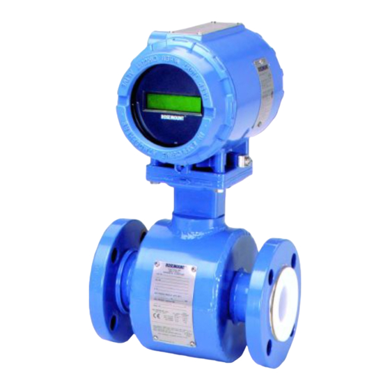
System Description
Provides an overview of the Rosemount 8700 Series Magnetic Flowmeter System, its components, and function.
Safety Messages
Details essential safety precautions and warnings to ensure personnel and equipment safety during operations.
Return of Materials
Outlines the procedure for returning products, including contact information and required documentation.
SECTION 2 Installation
Safety Information
Highlights critical safety guidelines and warnings pertinent to the installation process to prevent injury or damage.
Transmitter Symbols
Explains the meaning of various symbols used in the manual, such as caution and grounding terminals.
Pre-Installation
Covers essential pre-installation tasks like identifying options, configuring switches, and site selection considerations.
Changing Hardware Switch Settings
Provides step-by-step instructions for modifying hardware switch settings on the transmitter for specific configurations.
Rotate Transmitter Housing
Explains the procedure for rotating the transmitter housing in 90° increments for optimal orientation.
Wiring
Covers essential information regarding conduit ports, connections, and cable preparation for electrical wiring.
Transmitter Coil Input
Explains the four-wire transmitter configuration and how to wire it for power supply and coil drive.
Installation Category
States the installation category for the Rosemount 8742C as Category II.
Overcurrent Protection
Details the need for overcurrent protection for supply lines and provides fuse ratings for different power systems.
Transmitter Communication Input
Specifies the voltage requirements for FOUNDATION fieldbus communication and notes on applying voltage.
Power Conditioning
Explains the necessity of a power conditioner for decoupling the power supply output from the fieldbus wiring segment.
Field Wiring
Provides recommendations for field wiring, including using shielded, twisted-pair cables for FOUNDATION fieldbus.
Transmitter Wiring Connection
Details the process of making the transmitter communication wiring connection, including polarity and terminal tightening.
Transmitter to Flowtube Wiring
Explains the wiring requirements between the transmitter and flowtube, including conduit usage and cable types.
Flowtube to Remote Mount Transmitter Connections
Provides wiring diagrams and requirements for connecting flowtubes to remotely mounted transmitters.
Flowtube to Integral Mount Transmitter Connections
Illustrates wiring diagrams and specifications for connecting flowtubes to integrally mounted transmitters.
SECTION 3 Flowtube Installation
Safety Messages
Highlights critical safety precautions for personnel performing flowtube installation to prevent injury or equipment damage.
Flowtube Handling
Provides guidance on safely handling flowtubes, including transport, protection of liners, and lifting procedures.
Flowtube Mounting
Covers the physical mounting of the flowtube, similar to installing a pipe section, and required tools.
Upstream/Downstream Piping
Specifies the minimum straight pipe diameters required upstream and downstream of the flowtube for accuracy.
Flowtube Orientation
Details proper flowtube orientation to ensure it remains full, minimizing effects of entrapped gas and optimizing electrode placement.
Flow Direction
Explains mounting the flowtube to ensure the FORWARD end points in the direction of flow, as indicated by the identification tag.
Installation (Flanged Flowtube)
Guides the installation of flanged Rosemount 8705 and 8707 High-Signal Flowtubes, including gasket and flange bolt requirements.
Installation (Wafer Flowtube)
Guides the installation of the Rosemount 8711 Wafer Flowtube, detailing gasket and alignment/bolting procedures.
Installation (Sanitary Flowtube)
Outlines the installation process for the Rosemount 8721 Sanitary Flowtube, covering gasket, alignment, and bolting.
Process Leak Protection (Optional)
Describes optional housing configurations (W0, W1, W3) designed for process leak containment and protection.
Standard Housing Configuration
Explains the standard housing configuration (W0), its features, and limitations regarding process leaks.
Relief Valves
Describes the optional housing configuration (W1) with a relief valve for overpressure prevention, including its venting mechanism.
Process Leak Containment
Explains the optional housing configuration (W3) with sealed electrode compartments for containing process fluid leaks.
SECTION 4 Configuration
Calibration
States that Rosemount flowtubes are factory calibrated and do not require further calibration during installation.
Quick Start-Up
Outlines the initial steps for configuring the transmitter after installation and communication establishment.
Flowtube Calibration Number
Explains the purpose and format of the unique flowtube calibration number used for transmitter compatibility.
Assigning Device Tag and Node Address
Describes how to assign a device tag and node address using configuration tools for device identification.
AI Block
Details the Analog Input (AI) function block, its parameters, and its role in interfacing measurements with control systems.
Arithmetic Block
Explains the Arithmetic function block, its capabilities for compensation, augmentation, and supported arithmetic types.
Integrator
Describes the Integrator (INT) function block, its ability to integrate variables over time, and its support for mode control.
PID Block
Details the PID function block, its logic for control, supported modes, and equation structures.
Configuring Links and Scheduling Block Execution
Emphasizes the importance of configuring links and scheduling blocks for correct application execution, often using a GUI.
Advanced Applications
Illustrates advanced control configurations, showing how different function blocks can be interconnected for complex applications.
Cascade Control
Explains the configuration requirements for cascade control applications, involving linking AI and PID blocks between transmitters.
Resource Block
Provides information on the Resource Block, its parameters (FEATURES, FEATURE_SEL), and their impact on optional transmitter behavior.
FEATURES and FEATURES_SEL
Details the FEATURES and FEATURE_SEL parameters that determine supported features and enable write lock capabilities.
MAX_NOTIFY
Explains the MAX_NOTIFY parameter, which controls the maximum number of alert reports sent without confirmation.
PlantWeb™ Alarms
Describes how the Resource Block coordinates PlantWeb alarms, including alarm parameters and recommended actions for detected errors.
SECTION 5 Operation and Maintenance
Safety Information
Highlights crucial safety precautions for personnel performing operation and maintenance tasks to prevent injury or equipment damage.
Software Operation
Provides specific instructions for operating the Rosemount 8742C Transmitter, with examples using DeltaV as the host system.
Local Display Configuration
Explains how to configure the local display, including setting the display language and viewing status messages.
Calibration
Reaffirms that flowtubes are factory calibrated and do not require periodic calibration.
Electronics Trim
Details the electronics trim procedure, typically only needed if accuracy is suspected, requiring a calibration standard.
Auto Zero Trim
Explains the Auto Zero Trim function, used to initialize the transmitter for the 37.5 Hz coil drive mode, requiring zero flow and full pipe.
Configuring the Advanced Diagnostics and Empty Pipe
Guides users on enabling or disabling magmeter diagnostics and configuring the Empty Pipe functionality via the diagnostics tab.
Learning Empty Pipe
Describes the process of learning empty pipe functionality by measuring electrode resistance, useful for batch applications.
Diagnostics
Explains how magmeter-specific diagnostics appear on the detailed status screen, indicating triggered diagnostics with visual cues.
Hardware Maintenance
Covers basic hardware maintenance for the transmitter, noting its modular design and minimal scheduled maintenance requirements.
Replacing the FOUNDATION™ Fieldbus Electronics Housing
Details the procedure for replacing the electronics housing of the transmitter, applicable for both integral and remote mount units.
SECTION 6 Troubleshooting
Step 1: Function Block Errors
Points to appendices for specific troubleshooting of resource and transducer block errors.
Step 2: Diagnostic Messages
Guides troubleshooting using local display messages and detailed status indicators on the transducer block.
Step 3: Wiring Errors
Addresses common wiring issues between flowtube and transmitter in remote mount installations, emphasizing shielded cable.
Step 4: Process Noise
Offers solutions for unstable meter output caused by process conditions, including auto zero and damping adjustments.
Step 5: Installed Flowtube Tests
Provides a chart to assist in troubleshooting installed flowtubes, requiring disconnection of power and knowledge of certifications.
Step 6: Uninstalled Flowtube Tests
Explains how to troubleshoot uninstalled flowtubes using circuit diagrams and resistance readings, referencing tables for specific models.
APPENDIX A Reference Data
Rosemount 8742C Transmitter Specifications
Lists functional, performance, physical specifications, and electrical data for the Rosemount 8742C transmitter.
Rosemount 8705 and 8707 Flowtubes Specifications
Details functional specifications, service, line sizes, interchangeability, and upper range limits for 8705 and 8707 flowtubes.
Rosemount 8711 Wafer Flowtube Specifications
Covers functional specifications, service, line sizes, interchangeability, temperature limits, and pressure ratings for the 8711 wafer flowtube.
Rosemount 8714D Specifications
Lists functional, performance, and physical specifications for the Rosemount 8714D Reference Calibration Standard.
Dimensional Drawings
Presents dimensional drawings for the Rosemount 8742C transmitter, showing key measurements and connection ports.
Ordering Information
Provides detailed ordering information, including model numbers, product descriptions, options, and certifications for the 8742C.
APPENDIX B Product Certifications
Approved Manufacturing Locations
Lists the approved manufacturing locations for Rosemount products, including facilities in the USA and Mexico.
European Directive Information
Provides information on applicable European directives and where to find declarations of conformity for the product.
Hazardous Location Certifications
Details equivalent hazardous location certifications for flowtubes and transmitters, essential for safe installation in hazardous environments.
Transmitter Approval Information
Lists North American and European approval codes for transmitters, specifying conditions for intrinsic safety and explosion-proof ratings.
Flowtube Approval Information
Summarizes flowtube option codes and their corresponding hazardous location certifications for various models and fluid types.
APPENDIX C Resource Block
Definition
Defines the resource block as the component managing device resources, functionality, and memory-level diagnostics.
Parameters and Descriptions
Lists and describes all configurable parameters of the resource block, including their index numbers and functions.
Resource Block Errors
Details conditions reported in the BLOCK_ERR parameter for the resource block, providing error numbers and descriptions.
Modes
Explains the two modes of operation for the resource block: Automatic (Auto) and Out of Service (O/S).
Troubleshooting
Provides guidance on troubleshooting resource block problems, including issues with modes, block alarms, and notification settings.
APPENDIX D Transducer Block
Definition
Defines the transducer block as the component containing actual flow measurement data, sensor type, and diagnostics.
Parameters and Descriptions
Lists and describes all configurable parameters of the transducer block, including calibration, damping, and sensor settings.
Flow-Specific Block Configuration Values
Lists essential flow-specific parameters required for transmitter configuration, such as flowtube calibration number and engineering units.
Transducer Block Errors
Lists conditions reported in BLOCK_ERR and XD_ERROR parameters for the transducer block, covering various error types.
Transducer Block Diagnostics
Explains how to obtain detailed measurement status via DETAILED_STATUS and lists potential errors with corrective actions.
Modes
Describes the two modes of operation for the transducer block: Automatic (Auto) and Out of Service (O/S).
Troubleshooting
Provides a table for troubleshooting transducer block problems, linking symptoms to possible causes and corrective actions.
APPENDIX E Field-Removable Electrodes
Safety Messages
Highlights critical safety precautions for personnel handling field-removable electrodes to prevent injury or equipment damage.
Remove the Electrode Assembly
Details the step-by-step procedure for removing the electrode assembly from the flowtube, including fluid draining and screw removal.
Replace the Electrode Assembly
Provides instructions for replacing the electrode assembly, including lubricating the o-ring, seating the electrode, and securing components.
Need help?
Do you have a question about the 8700 Series and is the answer not in the manual?
Questions and answers