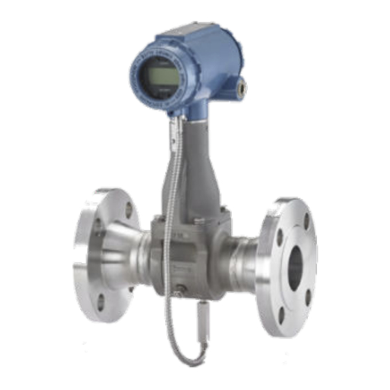
Emerson Rosemount 8800D Technical Notes
Calibration verification practices vortex flowmeters (hart protocol)
Hide thumbs
Also See for Rosemount 8800D:
- Reference manual (192 pages) ,
- Quick start manual (56 pages) ,
- Quick installation manual (31 pages)
Table of Contents
Advertisement
Quick Links
Download this manual
See also:
Reference Manual
Technical Note
00840-0300-4004, Rev AA
June 2010
Calibration Verification Practices
Rosemount 8800D Vortex Flowmeters (HART
INTRODUCTION
This guideline is intended for users of Rosemount
8800D Vortex flowmeters to develop plant specific
calibration/verification procedures and is focused
on procedures that do not require the removal of
the vortex meter body from the line or shutdown of
the line. This document shall provide the basis for
verification of the calibration of Rosemount 8800D
Vortex flowmeters. It does not include calibration
applications associated with the F
fieldbus communication protocol. It was prepared
by Technical Specialists at Rosemount Flow
Division's headquarters in Eden Prairie, MN, USA.
Overview
This section is for the use of those who are
generally experienced in the calibration and
verification of electronic transmitters including the
use of a Field Communicator and/or AMS Device
Manager. It is not intended to replace the general
calibration/verification procedures as detailed in
Section 2, the 475 Field Communicator Manual, or
the Rosemount 8800 Vortex flowmeter user's
manual. This section will outline the
documentation and hardware required for
calibration/verification of the Rosemount 8800
Vortex flowmeter.
Documentation Required
•
Applicable Instrument Specifications (latest
revision)
•
Instrument Verification Report form (see
"Appendix A: Electronics Verification Form"
on page 8)
•
Factory Calibration Report
•
Rosemount 8800D Vortex Flowmeter
Manual 00809-0100-4004 (optional)
http://www.emersonprocess.com/rosemount
/document/man/00809-0100-4004.pdf
•
Field Communicator Manual
00809-0100-4276 (optional)
http://www.documentation.emersonprocess.
com/groups/public_assetoptprodlit/documen
ts/instruction_manuals/475_allma_userman
ual.pdf
www.rosemount.com
OUNDATION
Rosemount 8800D
If there are any questions, or more information is
required, please contact the Rosemount technical
support at 1-800-999-9307 or via e-mail at
Specialist-Vortex.EPM-RTC@emerson.com.
Hardware and Tools Required:
•
Power supply, 10-55 VDC
1
•
Multi-meter, 4-
/
digits (within NIST
2
traceable calibration compliance time
period)
•
475 Field Communicator or AMS Device
Manager
•
Precision Load Resistor: 250 ohms +/-
0.01% 2 watt or 500 ohms +/- 0.01% 2 watt
•
Jumper wires with end connectors
•
Temperature Sensor Calibrator or Calibrated
Oil Bath (MTA Option Only)
Pre-Configuration Checks (Field
Communicator not connected to transmitter)
•
Verifying the Security Jumper Status
Insure that power is removed from the transmitter.
Remove the housing cover opposite the field
terminal side. Position the security jumper as
desired. If the Security jumper is not installed –
SECURITY OFF (NOT write protected).
™
Protocol)
Advertisement
Table of Contents

Subscribe to Our Youtube Channel
Related Manuals for Emerson Rosemount 8800D


Summary of Contents for Emerson Rosemount 8800D
- Page 1 Power supply, 10-55 VDC the line. This document shall provide the basis for • Multi-meter, 4- digits (within NIST verification of the calibration of Rosemount 8800D traceable calibration compliance time Vortex flowmeters. It does not include calibration period) applications associated with the F OUNDATION •...
-
Page 2: Technical Note
Technical Note 00840-0300-4004, Rev AA Rosemount 8800D June 2010 CALIBRATION GUIDELINES Use Case III – 8800D Vortex meter with MTA Option using Process Fluids of Gas/Steam or This section provides the calibration verification Liquid procedure to follow for a given use case of the 1. - Page 3 Technical Note 00840-0300-4004, Rev AA Rosemount 8800D June 2010 Procedure I: Verify Basic Configuration HART Commands: 1 (Device Setup), 3 (Basic Paramaters Setup), 2 (Process Config), 4 (Density/Density Ratio), 2 (Fixed Process Density) NOTE: B.1 IF the Process Density is correct, press Make sure that the flowmeter is powered properly.
- Page 4 Technical Note 00840-0300-4004, Rev AA Rosemount 8800D June 2010 Step 5: Flange Type Step 8: Primary Variable Units A. Verify the correct Flange Type has been A. Verify the correct Primary Variable Unit has entered into the vortex meter. The vortex been selected (i.e.
- Page 5 Technical Note 00840-0300-4004, Rev AA Rosemount 8800D June 2010 Procedure II. Electronics Verification through Step 4:Verify that flow rate output is 50% of Flow Simulation full scale HART Commands: 1 (Device Setup), 2 (Diagnostics NOTE: and Service), 4 (Flow Simulation), 1 (Flow)
- Page 6 Damage to the sensor cable may occur if the sensor transmitters are verified as individual units. However, cable is stressed. due to the Rosemount 8800D design that uses a Type N special limits thermocouple and a custom interface between the thermocouple and the G.
- Page 7 Technical Note 00840-0300-4004, Rev AA Rosemount 8800D June 2010 Step 5:Set temperature sensor calibrator or Step 3:Enter a process temperature of interest precision liquid bath to a set point of 100 °C between 80-320 °C (176-608 °F) (212 °F) Step 4:Compare calculated density to ASME Saturated Steam Table found in APPENDIX C A.
-
Page 8: Appendix A: Electronics Verification Form
Technical Note 00840-0300-4004, Rev AA Rosemount 8800D June 2010 APPENDIX A: ELECTRONICS VERIFICATION FORM TABLE 1. Unit Conversion Factors Units Conversion Units Procedure Steps – Readings are taken while the (Actual) Factor (Cx) (Actual) Conversion Factor (Cx) transmitter is in Flow Simulation mode. -
Page 9: Appendix B: Vortex Sensor Health Verification
Technical Note 00840-0300-4004, Rev AA Rosemount 8800D June 2010 APPENDIX B: VORTEX SENSOR HEALTH VERIFICATION Verifying Vortex Sensor if Signal-to-Trigger Level is less than 4 STEP 1: Check Sensor and sensor lead wire for shorts a) Isolated from the process... - Page 10 Technical Note 00840-0300-4004, Rev AA Rosemount 8800D June 2010 Replacing Sensor - Safety Considerations • Replaceable sensor also serves as a secondary seal up to Flange Rating with metal O-ring • Recommended procedure for replacing a sensor is to de-pressurize the flow process...
- Page 11 Technical Note 00840-0300-4004, Rev AA Rosemount 8800D June 2010 TABLE 2. ASME Saturated Steam Table (English Units) Temperature (°F) Density (lbs/ft Temperature (°F) Density (lbs/ft Temperature (°F) Density (lbs/ft 0.0183 0.2175 1.1658 0.0199 0.2322 1.2237 0.0221 0.2477 1.2842 0.0244 0.2640 1.3473...
- Page 12 The Emerson logo is a trade mark and service mark of Emerson Electric Co. Rosemount and the Rosemount logotype are registered trademarks of Rosemount Inc. PlantWeb is a registered trademark of one of the Emerson Process Management group of companies. All other marks are the property of their respective owners.
Need help?
Do you have a question about the Rosemount 8800D and is the answer not in the manual?
Questions and answers