Emerson Rosemount 8800D Series Safety Manual
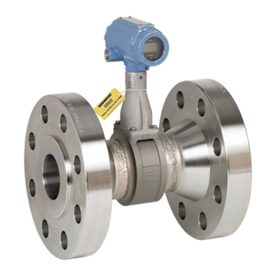
Vortex flowmeter
safety manual for safety instrumented systems
Hide thumbs
Also See for Rosemount 8800D Series:
- Reference manual (192 pages) ,
- Quick start manual (56 pages) ,
- Quick installation manual (31 pages)
Table of Contents
Advertisement
Quick Links
Download this manual
See also:
Reference Manual
Advertisement
Table of Contents

Related Manuals for Emerson Rosemount 8800D Series


Summary of Contents for Emerson Rosemount 8800D Series
- Page 1 Safety Manual 00809-0200-4004, Rev AA October 2017 ™ Rosemount 8800D Series Vortex Flowmeter Safety Manual for Safety Instrumented Systems (SIS)
-
Page 3: Table Of Contents
Contents Contents Chapter 1 Before you begin ......................1 Emerson Flow customer service ..................... 2 About this document ........................2 Related documents ........................3 Terms and definitions ........................3 Skill level requirement ........................4 Documentation and standards ....................... 4 Chapter 2 Installation and commissioning ..................7 Identification of SIS certified transmitter .................. - Page 4 Contents ™ Rosemount 8800D Safety Manual...
-
Page 5: Before You Begin
Before you begin Before you begin Topics covered in this chapter: • Emerson Flow customer service • About this document • Related documents • Terms and definitions • Skill level requirement • Documentation and standards Safety Manual... -
Page 6: Emerson Flow Customer Service
About this document This document provides information about how to install, commission, and proof test the Rosemount 8800D Series SIL 2/3 Capable Vortex Flowmeter to comply with Safety Instrumented Systems (SIS) requirements. The information in this document assumes that users understand: •... -
Page 7: Related Documents
Before you begin Related documents You can find all product documentation via the Rosemount product documentation DVD shipped with the product or at www.emerson.com/vortex. For more information, see any of the following documents: ® • Rosemount 8800D Series Vortex Flow Meter Product Data Sheet ®... -
Page 8: Skill Level Requirement
Before you begin High demand The safety function is only performed on demand, in order to transfer the EUC (Equipment Under Control) into a specified safe mode state, and where the frequency of demands is greater than one per year (IEC 61508-4). The safety function is only performed on demand, in order to Low demand mode... - Page 9 Before you begin Documents Purpose of documents IEC 61508-2: 2010 Functional Safety of Electrical/Electronic/Programmable Electronic Safety-Related Systems IEC 61511 (ANSI/ISA Functional safety - Safety instrumented systems for the process industry 84.00.01-2004) sector ROS 06/03-34 R001 FMEDA Report Version V1, Revision R1, or later, for the Rosemount 8800D Series Vortex Flowmeter ®...
- Page 10 Before you begin ™ Rosemount 8800D Safety Manual...
-
Page 11: Installation And Commissioning
• Flow simulation diagnostic • Replace equipment Use this chapter to install and commission the Rosemount 8800D Series SIL 2/3 Capable Vortex Flowmeter. Identification of SIS certified transmitter IEC 61508 relevant requirements The Rosemount 8800D is certified per the relevant requirements of IEC 61508. - Page 12 Installation and commissioning Verify the option code "SI" in the model code. The SI code will appear somewhere after the 16th character of the model code (after the required fields.) Note that the optional options, including SI, can appear in any order and be valid. Please refer to A Figure 2-1.
-
Page 13: Set Up The Flowmeter
Installation and commissioning Safety precautions Prior to making any changes to the flowmeter,such as changing the configuration or replacing the transmitter hardware or sensor: • Take appropriate action to avoid a false trip by electronically bypassing the safety logic solver. •... -
Page 14: Enable Transmitter Write Protection
Installation and commissioning Enable transmitter write protection Write-protection helps protect the transmitter against accidental changes to configuration. When the transmitter is write-protected, no changes to the transmitter configuration will be accepted. Write protecting the transmitter prevents accidental changes to configuration. It does not prevent normal operational use. -
Page 15: Set Failure Mode
Installation and commissioning Figure 2-3: SECURITY jumper location with M5 optional display Replace the transmitter housing cover. Power up the transmitter. Set failure mode As part of normal operations, the flowmeter continuously runs a self-diagnostic routine. If the routine detects an internal failure, the failure mode setting determines whether the flowmeter output is driven to a low or high alarm level. -
Page 16: Flow Simulation Diagnostic
Installation and commissioning The location of the ALARM jumper depends upon whether or not the transmitter has the (M5) optional display. Figure 2-4: ALARM jumper location without (M5) optional display Figure 2-5: ALARM jumper location with (M5) optional display Replace the transmitter housing cover. Power up the transmitter. -
Page 17: Replace Equipment
Section 2.3). Replace equipment If you need to replace hardware, purchase all spare parts from Emerson. You cannot use user-supplied components on any Rosemount printed circuit assemblies. Replace the hardware by contacting your local Emerson or Emerson affiliated sales representative to obtain the correct part number. - Page 18 Installation and commissioning Use the product reference manual or quick start guide for proper maintenance guidelines. Verify the transmitter configuration and all safety parameters (see Section 2.2). Enable write protection (see Section 2.3). Set the failure mode (see Section 2.4.) ™...
-
Page 19: Chapter 3 Proof Tests
Repair procedures in the product reference manual must be followed. Notification of failures In case of malfunction of the system or SIF, the Rosemount 8800D Series SIL 2/3 Capable Vortex Flowmeter shall be put out of operation and the process shall be kept in a safe state by other measures. -
Page 20: Proof Test Interval
3 to 5-point calibration check using reference Low flow trip: standard • Checking for alarms • Checking configuration Partial proof test The partial proof test is recommended for all Rosemount 8800D Series SIL 2/3 Capable Vortex Flowmeters. ™ Rosemount 8800D Safety Manual... -
Page 21: Comprehensive Proof Test
Remove the bypass and otherwise restore normal operation. Document the results of this proof test as part of your plant safety management procedures. Comprehensive proof test The comprehensive proof test is recommended for all Rosemount 8800D Series SIL 2/3 Capable Vortex Flowmeters. Safety Manual... -
Page 22: Sis Example
Proof tests This procedure assumes that you are familiar with plant procedures. For details on how to do any of the following steps, see the product reference manual. Procedure Take appropriate action to avoid a false trip by electronically bypassing the safety Programmable Logic Controller (PLC). - Page 23 Proof tests Figure 3-1: Single use 1oo1 (1 out of 1) for SIL 2 low demand (SIL 2@HFT=0) Sensor (Rosemount 8800D) Logic solver Actuator Figure 3-2: PFD and PFD average of system when no proof testing applied PFD (Probability of failure on demand) Mission time (years) (average probability of failure on demand) Predicted PFD...
- Page 24 Proof tests Figure 3-3: Unit subjected to either no proof test or a comprehensive proof test every 5 years PFD (Probability of failure on demand) Mission time (years) (average probability of failure on demand) Predicted PFD Predicted PFD + CPT (comprehensive proof test) Figure 3-4: Unit subjected to a partial proof test every year and a comprehensive proof test every 3 years...
- Page 25 Proof tests Figure 3-5: Unit subjected to a partial proof-test every year and a comprehensive proof test every 5 years PFD (Probability of failure on demand) Mission time (years) (average probability of failure on demand) Predicted PFD + PPT (partial proof test) + CPT (comprehensive proof test) Safety Manual...
- Page 26 Proof tests ™ Rosemount 8800D Safety Manual...
-
Page 27: Chapter 4 Operating Constraints
Reverse flow operation may result in erroneous non-zero flow indication. Reliability data The Rosemount 8800D Series SIL 2/3 Capable Vortex Flowmeter: • Has a specified safety deviation of 2%. Internal component failures are listed in the device failure rate if they will cause an on-scale error of 2% or greater. -
Page 28: Report Failures
Operating Constraints Report failures If you have detected any failures that compromise safety, contact the Flow Solutions Group Product Safety Officer. Contact the Product Safety Officer through the Flow Solutions Group customer service. Customer service is available 24 hours a day, seven days a week. Contact information is located at the front of this manual. - Page 29 Operating Constraints Safety Manual...
- Page 30 © 2017 Rosemount, Inc. All rights reserved. The Emerson logo is a trademark and service mark of Emerson Electric Co. Rosemount, 8600, 8700, 8800 marks are marks of one of the Emerson Automation Solutions family of companies. All other marks are property of their respective owners.
Need help?
Do you have a question about the Rosemount 8800D Series and is the answer not in the manual?
Questions and answers