EWM Tetrix 352 Synergic Operating Instructions Manual
Hide thumbs
Also See for Tetrix 352 Synergic:
- Operating instructions manual (81 pages) ,
- Operating instructions manual (94 pages)

Related Manuals for EWM Tetrix 352 Synergic


Summary of Contents for EWM Tetrix 352 Synergic
- Page 1 Operating instructions Power source Tetrix 352, 452, 552 Synergic 099-000141-EW501 Observe additional system documents! 12.01.2016...
- Page 2 +49 2680 181-0. A list of authorised sales partners can be found at www.ewm-group.com. Liability relating to the operation of this equipment is restricted solely to the function of the equipment.
-
Page 3: Table Of Contents
Contents Notes on the use of these operating instructions Contents Contents ..............................3 Safety instructions ..........................6 Notes on the use of these operating instructions ................6 Explanation of icons ........................7 General ............................ - Page 4 Contents Notes on the use of these operating instructions 5.14 Arc ignition ........................... 46 5.14.1 HF ignition ........................46 5.15 Optimising the ignition characteristics for pure tungsten electrodes ........... 47 5.15.1 TIG automatic cut-out ....................47 ...
- Page 5 Circuit diagrams ........................... 90 10.1 Tetrix 352, 452, 552 ........................90 Appendix A ............................93 11.1 JOB-List ............................93 Appendix B ............................97 12.1 Overview of EWM branches ......................97 099-000141-EW501 12.01.2016...
-
Page 6: Safety Instructions
Safety instructions Notes on the use of these operating instructions Safety instructions Notes on the use of these operating instructions DANGER Working or operating procedures which must be closely observed to prevent imminent serious and even fatal injuries. • Safety notes include the "DANGER" keyword in the heading with a general warning symbol. •... -
Page 7: Explanation Of Icons
Safety instructions Explanation of icons Explanation of icons Symbol Description Special technical points which users must observe. Correct Wrong Press Do not press Press and keep pressed Turn Switch Switch off machine Switch on machine enter the menu ENTER Navigating in the menu NAVIGATION Exit the menu EXIT... -
Page 8: General
Safety instructions General General DANGER Electric shock! Welding machines use high voltages which can result in potentially fatal electric shocks and burns on contact. Even low voltages can cause you to get a shock and lead to accidents. • Do not touch any live parts in or on the machine! •... - Page 9 Safety instructions General WARNING Explosion risk! Apparently harmless substances in closed containers may generate excessive pressure when heated. • Move containers with inflammable or explosive liquids away from the working area! • Never heat explosive liquids, dusts or gases by welding or cutting! Smoke and gases! Smoke and gases can lead to breathing difficulties and poisoning.
- Page 10 Safety instructions General CAUTION Obligations of the operator! The respective national directives and laws must be observed for operation of the machine! • National implementation of the framework directive (89/391/EWG), as well as the associated individual directives. • In particular, directive (89/655/EWG), on the minimum regulations for safety and health protection when staff members use equipment during work.
- Page 11 Safety instructions General CAUTION EMC Machine Classification In accordance with IEC 60974-10, welding machines are grouped in two electromagnetic compatibility classes - See 8 Technical data chapter: Class A machines are not intended for use in residential areas where the power supply comes from the low-voltage public mains network.
-
Page 12: Transport And Installation
Safety instructions Transport and installation Transport and installation WARNING Incorrect handling of shielding gas cylinders! Incorrect handling of shielding gas cylinders can result in serious and even fatal injury. • Observe the instructions from the gas manufacturer and in any relevant regulations concerning the use of compressed air! •... -
Page 13: Lifting By Crane
Safety instructions Transport and installation 2.4.1 Lifting by crane WARNING Risk of injury during lifting by crane When lifting the machine by crane, persons may be severely injured by falling machines or mount-on components. • Simultaneous lifting of system components such as power source wire feeder or cooling unit without suitable crane components is not allowed. -
Page 14: Ambient Conditions
Safety instructions Transport and installation 2.4.2 Ambient conditions CAUTION Installation site! The machine must not be operated in the open air and must only be set up and operated on a suitable, stable and level base! • The operator must ensure that the ground is non-slip and level, and provide sufficient lighting for the place of work. -
Page 15: Intended Use
Intended use Use and operation solely with the following machines Intended use WARNING Hazards due to improper usage! Hazards may arise for persons, animals and material objects if the equipment is not used correctly. No liability is accepted for any damages arising from improper usage! •... -
Page 16: Documents Which Also Apply
3.2.1 Warranty For more information refer to the "Warranty registration" brochure supplied and our information regarding warranty, maintenance and testing at www.ewm-group.com! 3.2.2 Declaration of Conformity The designated machine conforms to EC Directives and standards in terms of its design and construction: •... -
Page 17: Machine Description - Quick Overview
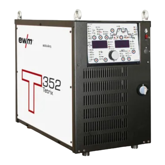
Machine description – quick overview Front view Machine description – quick overview Front view Figure 4-1 Item Symbol Description Lifting lug Machine control- See 4.3 Machine control (Mode RC - on) chapter PC interface, serial (D-Sub connection socket, 9-pole) • Retrofitting option • Key switch for protection against unauthorised use Position “1”... -
Page 18: Rear View
Machine description – quick overview Rear view Rear view Figure 4-2 Item Symbol Description Interfaces Optional interface in the extension casing for assembly onto the power source digital • RINTX11 robot interface • BUSINTX10 industrial bus interface 19-pole mechanised welding interface (analogue) - See 5.21.5 Automation interface chapter analog 8-pole connection socket... - Page 19 Machine description – quick overview Rear view Item Symbol Description Key button, automatic cutout Wire feed motor supply voltage fuse press to reset a triggered fuse G¼" connection thread, shielding gas connection, inlet Cooling air outlet Mains connection cable - See 5.6 Mains connection chapter 5-pole connection socket Cooling unit voltage supply Intermediate hose package strain relief...
-
Page 20: Machine Control (Mode Rc - On)
Machine description – quick overview Machine control (Mode RC - on) Machine control (Mode RC - on) This welding machine is operated in 'RC – on, remote-controlled' mode ex works. RC – on: The machine is controlled via an external interface in this mode. The majority of operating elements on the machine control are deactivated and are used to check the welding data only. - Page 21 Machine description – quick overview Machine control (Mode RC - on) Item Symbol Description Welding parameter setting rotary dial Setting currents, times and parameters. Welding data display (3-digit) Displays the welding parameters and the corresponding values Display switching button Material thickness display VOLT Welding voltage display JOB number display...
-
Page 22: Function Sequence
Machine description – quick overview Machine control (Mode RC - on) 4.3.1 Function sequence AMP% AMP% AMP% activArc Figure 4-4 Item Symbol Description Select welding parameters button This button is used to select the welding parameters depending on the welding process and operating mode used. - Page 23 Machine description – quick overview Machine control (Mode RC - on) Item Symbol Description Gas post-flow time (TIG) Setting ranges: 0.00 sec to 40.0 sec (0.1 sec increments). Balance TIG kHz-pulsing (metallurgical pulsing) Setting range: 1% to +99% (increments of 1%) MMA pulse welding Setting range: 1% to +99% (increments of 1%) Frequency...
-
Page 24: Machine Control (Mode Rc - Off)
Machine description – quick overview Machine control (Mode RC - off) Machine control (Mode RC - off) T 3.27 Puls Automatic AMP% AMP% AMP% > HOLD VOLT Synergic PROG CrNi Fe/St Synergic CuZn Manuell Spez Figure 4-5 Item Symbol Description "Welding process"... - Page 25 Machine description – quick overview Machine control (Mode RC - off) Item Symbol Description Operating mode / Power-saving mode button spotArc / Spotmatic (spot time setting range) Non-latched Latched Press for 3 s to put machine into power-saving mode. To reactivate, activate one of the operating elements- See 5.23.3 Power-saving mode (Standby) chapter.
-
Page 26: Function Sequence
Machine description – quick overview Machine control (Mode RC - off) 4.4.1 Function sequence AMP% AMP% AMP% activArc Figure 4-6 Item Symbol Description Select welding parameters button This button is used to select the welding parameters depending on the welding process and operating mode used. - Page 27 Machine description – quick overview Machine control (Mode RC - off) Item Symbol Description Gas post-flow time (TIG) Setting ranges: 0.00 sec to 40.0 sec (0.1 sec increments). Balance TIG kHz-pulsing (metallurgical pulsing) Setting range: 1% to +99% (increments of 1%) MMA pulse welding Setting range: 1% to +99% (increments of 1%) Frequency...
-
Page 28: Design And Function
Design and function General Design and function General WARNING Risk of injury from electric shock! Contact with live parts, e.g. welding current sockets, is potentially fatal! • Follow safety instructions on the opening pages of the operating instructions. • Commissioning may only be carried out by persons who have the relevant expertise of working with arc welding machines! •... -
Page 29: Installation
Design and function Installation CAUTION Damage due to incorrect connection! Accessory components and the power source itself can be damaged by incorrect connection! • Only insert and lock accessory components into the relevant connection socket when the machine is switched off. •... -
Page 30: Welding Torch Cooling System
Design and function Welding torch cooling system Welding torch cooling system CAUTION Coolant mixtures! Mixtures with other liquids or the use of unsuitable coolants result in material damage and renders the manufacturer's warranty void! • Only use the coolant described in this manual (overview of coolants). •... -
Page 31: Mains Connection
Design and function Mains connection Mains connection DANGER Hazard caused by improper mains connection! An improper mains connection can cause injuries or damage property! • Only use machine with a plug socket that has a correctly fitted protective conductor. • If a mains plug must be fitted, this may only be carried out by an electrician in accordance with the relevant national provisions or regulations! •... -
Page 32: Notes On The Installation Of Welding Current Leads
Design and function Notes on the installation of welding current leads Notes on the installation of welding current leads Incorrectly installed welding current leads can cause faults in the arc (flickering). Lay the workpiece lead and hose package of power sources without HF igniter (MIG/MAG) for as long and as close as possible in parallel. - Page 33 Design and function Notes on the installation of welding current leads Use an individual welding lead to the workpiece for each welding machine! Figure 5-3 Fully unroll welding current leads, torch hose packages and intermediate hose packages. Avoid loops! Always keep leads as short as possible! Lay any excess cable lengths in meanders.
-
Page 34: Shielding Gas Supply (Shielding Gas Cylinder For Welding Machine)
Design and function Shielding gas supply (shielding gas cylinder for welding machine) Shielding gas supply (shielding gas cylinder for welding machine) WARNING Incorrect handling of shielding gas cylinders! Incorrect handling of shielding gas cylinders can result in serious and even fatal injury. •... -
Page 35: Shielding Gas Setting
Design and function Shielding gas supply (shielding gas cylinder for welding machine) 5.8.2 Shielding gas setting Rule of thumb for the gas flow rate: Diameter of gas nozzle in mm corresponds to gas flow in l/min. Example: 7mm gas nozzle corresponds to 7l/min gas flow. Incorrect shielding gas setting! •... -
Page 36: Gas Supply
Design and function Gas supply Gas supply Figure 5-6 Item Symbol Description Shielding gas Shielding gas hose G¼" connection thread, shielding gas connection, inlet • Screw the crown nut on the shielding gas lead gastight to the connecting thread (G¼"). 099-000141-EW501 12.01.2016... -
Page 37: Connect The Cooling Unit To The Power Source
Design and function Connect the cooling unit to the power source 5.10 Connect the cooling unit to the power source Please note the relevant documentation of the accessory components. Figure 5-7 Item Symbol Description 5-pole connection socket Cooling unit voltage supply 8-pole connection socket Cooling unit control lead Cooling module... -
Page 38: Welding Torch Connection
Design and function Welding torch connection 5.11 Welding torch connection Figure 5-8 Item Symbol Description 19-pole (analogue) connection socket Collision protection / sensor voltage control signals G¼" connection thread, shielding gas connection, outlet Connection socket, welding current - Welding torch connection Welding torch hose package Welding torch •... -
Page 39: Connecting The Welding Torch To The Tig Torch Box
Design and function Welding torch connection 5.11.1 Connecting the welding torch to the TIG TORCH BOX Figure 5-9 Item Symbol Description Automated welding torch Welding torch hose package Connecting nipple G¼, shielding gas connection Quick connect coupling (red) coolant return “-”... -
Page 40: Connecting The Tig Torch Box To The Power Source
Design and function Welding torch connection 5.11.2 Connecting the TIG TORCH BOX to the power source When using a TIG TORCH BOX the gas supply must be connected directly to the TIG TORCH BOX. Gas monitoring can be configured using the Tool EWMConfig.Net. Figure 5-10 Item Symbol Description... -
Page 41: Connection For Workpiece Lead
Design and function Connection for workpiece lead 5.12 Connection for workpiece lead Figure 5-11 Item Symbol Description Workpiece Connection socket, “+” welding current Workpiece connection • Insert cable plug on the workpiece lead into the connection socket for workpiece lead and lock by turning to the right. -
Page 42: Tig Synergic Operating Principle
Design and function TIG Synergic operating principle 5.13 TIG Synergic operating principle T 3.27 Puls Automatic AMP% AMP% AMP% > HOLD VOLT Synergic PROG CrNi Fe/St Synergic CuZn Manuell Spez Figure 5-12 The machine is operated according to the TIG Synergic operating principle: The three basic parameters •... -
Page 43: Synergic Parameter Setting In The Functional Sequence
Design and function TIG Synergic operating principle 5.13.1 Synergic parameter setting in the functional sequence When setting the welding current, all the necessary welding parameters are adjusted automatically during the functional sequence - See 4.4.1 Function sequence chapter with the exception of the gas pre-flow time. -
Page 44: Set The Operating Principle (Conventional/Synergic)
Design and function TIG Synergic operating principle 5.13.2.1 Set the operating principle (conventional/synergic) ENTER EXIT NAVIGATION Figure 5-15 Display Setting/selection Exit the menu Exit Machine configuration Settings for machine functions and parameter display Operating principle • on = synergic parameter setting (factory setting) •... -
Page 45: Welding Task Selection
Design and function TIG Synergic operating principle 5.13.3 Welding task selection The welding task is selected using the buttons on the machine control on the welding machine. Signal lights (LED) display the welding parameter selection. It is only possible to change the basic parameters when no welding current is flowing and any possible access control is disabled. -
Page 46: Welding Data Display
Design and function Arc ignition 5.13.5 Welding data display The following welding parameters can be displayed before (nominal values), during (actual values) or after welding (hold values): left-hand display Parameter Before welding During welding After welding (nominal values) (actual values) (hold values) Welding current ... -
Page 47: Optimising The Ignition Characteristics For Pure Tungsten Electrodes
Design and function Optimising the ignition characteristics for pure tungsten electrodes 5.15 Optimising the ignition characteristics for pure tungsten electrodes This parameter can be used to improve the ignition characteristics of “pure tungsten electrodes”, for example. The parameter is a %-value (factory-set to 20) and is changed across all JOBs. Control element Action Result... -
Page 48: Tig Welding Task Definition
Design and function TIG welding task definition 5.16 TIG welding task definition The user defines the welding tasks using JOB numbers. Each JOB number stores all the parameters relating to the welding task. The user can either load an existing JOB, load an existing JOB and change it, or define a completely new JOB via the various interfaces. -
Page 49: Pulse Variants
Design and function Pulse variants 5.17 Pulse variants This parameter setting is specified by the robot control via the RINT X12 or BUSINT X11 robot interface (see documentation in the relevant interface description). The machines have an integrated pulse device. With pulses, the machine switches back and forth between the pulse current (main current) and pause current (secondary current). -
Page 50: Protecting Welding Parameters From Unauthorised Access
Design and function Protecting welding parameters from unauthorised access 5.18 Protecting welding parameters from unauthorised access To protect against unauthorised or unintentional adjustment of the welding parameters on the machine, the control input can be locked with the aid of a key switch. Key position 1 = All parameters can be set Key position 0 =... -
Page 51: Selection And Adjustment
Design and function Welding programs 5.19.1 Selection and adjustment Setting welding programs using the welding machine control Operating Action Result Display element Press button until signal light PROG comes on. Welding current (left) and program no. (right) Select or retrieve program no., e.g. no. 1 Set operating mode (can be specified separately for each No change program). -
Page 52: Example "Program With Synergetic Setting
Design and function Welding programs 5.19.2 Example "Program with synergetic setting" Figure 5-19 5.19.3 Example "Program with conventional setting" Figure 5-20 5.19.4 Accessories for switching over programs The user can change, retrieve and save programs using the following components. Programs Component Create and change Retrieve... -
Page 53: Organising Welding Tasks (Mode "Job Manager")
Design and function Organising welding tasks (Mode "JOB Manager") 5.20 Organising welding tasks (Mode "JOB Manager") Welding jobs (JOBs) / programs are organised (configured, managed, created) using the parameterisation software PC300.Net. JOBs are switched with an interface (e.g., RINT X12). Please note the relevant documentation of the accessory components. -
Page 54: Creating A New Job In The Memory Or Copying A Job
Design and function Organising welding tasks (Mode "JOB Manager") 5.20.2 Creating a new JOB in the memory or copying a JOB Copying a pre-defined welding task from the fixed memory (JOBs 1 to 128) to the free memory (JOBs 129-256): It is normally possible to adjust all 256 JOBs individually. -
Page 55: Loading An Existing Job From The Free Memory
Design and function Organising welding tasks (Mode "JOB Manager") 5.20.3 Loading an existing JOB from the free memory Operating Action Result Display element Select JOB Manager mode Press until the “VOLT” signal light is on Select JOB Manager mode 2 sec. Select the required JOB number using the rotary transducer (e.g. -
Page 56: Resetting Jobs 1-128 To The Factory Setting (Reset All Jobs)
Design and function Organising welding tasks (Mode "JOB Manager") 5.20.5 Resetting JOBs 1-128 to the factory setting (Reset All JOBs) Operating Action Result Display element Select JOB Manager mode Press until the “VOLT” signal light is on Select JOB Manager mode 2 sec. -
Page 57: Spotarc
Design and function Organising welding tasks (Mode "JOB Manager") 5.20.7 spotArc This process is suitable for tack welding or joint welding of metal sheets made from steel and CrNi alloys up to a thickness of approximately 2.5 mm. Metal sheets of different thicknesses can also be welded on top of one another. - Page 58 Design and function Organising welding tasks (Mode "JOB Manager") Figure 5-21 As an example the process is shown with HF ignition. Arc ignition with lift arc is also possible, however. Sequence: • Press and hold torch trigger 1. • The gas pre-flow time elapses. •...
-
Page 59: Tig Activarc Welding
Organising welding tasks (Mode "JOB Manager") 5.20.8 TIG activArc welding The EWM activArc process, thanks to the highly dynamic controller system, ensures that the power supplied is kept virtually constant in the event of changes in the distance between the welding torch and the weld pool, e.g. -
Page 60: Interfaces
Design and function Interfaces 5.21 Interfaces 5.21.1 Connecting the robot interface / industrial bus interface CAUTION Damage due to the use of non-genuine parts! The manufacturer's warranty becomes void if non-genuine parts are used! • Only use system components and options (power sources, welding torches, electrode holders, remote controls, spare parts and replacement parts, etc.) from our range of products! •... -
Page 61: Rint X12 Robot Interface
Design and function Interfaces Figure 5-23 Item Symbol Description 7-pole connection socket (digital) For connecting digital accessory components Switching cabinet Robot interface / Industrial bus interface Interface casing ATCASE 7-pole connection cable Connection between switching cabinet and power source Connection lead Connection between interface casing and switching cabinet 5.21.1.1 RINT X12 robot interface The standard digital interface for mechanised applications... -
Page 62: Connecting The Pc 300.Net Welding Parameterisation Software
Design and function Interfaces 5.21.2 Connecting the PC 300.net welding parameterisation software Create all welding parameters quickly on the PC and easily transfer them to one or more welding machines (accessories, set consisting of software, interface, connection leads) Figure 5-24 Item Symbol Description PC interface, serial (D-Sub connection socket, 9-pole) -
Page 63: Connecting The Q-Doc 9000 Welding Data Documentation Software
Design and function Interfaces 5.21.3 Connecting the Q-DOC 9000 welding data documentation software (Accessories: Set consisting of software, interface, connection leads) The ideal tool for welding data documentation of, for example: welding voltage and current, wire speed and motor current. Figure 5-25 Item Symbol Description... -
Page 64: Connecting The Weldqas Welding Data Monitoring And Documentation System
Design and function Interfaces 5.21.4 Connecting the WELDQAS welding data monitoring and documentation system Network-compatible welding data monitoring and documentation system for digital power sources. Figure 5-26 Item Symbol Description 7-pole connection socket (digital) For connecting digital accessory components Windows PC WELDQAS welding data monitoring and documentation system 7-pole connection cable Connection between switching cabinet and power source... -
Page 65: Automation Interface
Design and function Interfaces 5.21.5 Automation interface WARNING No function of the external interrupt equipment (emergency stop switch)! If the emergency stop circuit has been set up using an external interrupt equipment connected to the interface for automated welding, the machine must be configured for this setup. - Page 66 Design and function Interfaces 19-pole connection assignments for mechanised welding interface (X6): Signal Circuit diagram Function shape signal name Output Connection for cable screen Input Pulsen ein Thermal pulse mode up to max. 50 Hz, fixed balance of Input SYN_E Synchronisation for master/slave operation Output IGRO Relais...
-
Page 67: Connection Socket Automation Torch
Design and function Interfaces 5.21.6 Connection socket automation torch X53- PE_Dyn. 2n2F PE_Dyn. PE_Dyn. BR KOLL1 BR KOLL2 0VAC Fühlerspannung Fühlerspannung Gastest TETRIX DRIVE 4 ROB Gasmangel only! Gasrelais +5V Tacho B Z Tacho B TB 0VAC Einfädeln A codiert Y Tacho B Y Tacho B 0V Tacho B... -
Page 68: Sensor Voltage
Design and function Interfaces 5.21.7 Sensor Voltage The sensor voltage is transmitted via PIN F of the mechanised welding torch connection socket (X53). Outside the welding process, there is a voltage of approx. 12 V on the welding torch electrode. If the electrode comes into contact with the workpiece or the molten pool, the short-circuit produced means that when using the relevant interface (BUSINT X11/RINT X12), the resultant signal can be used for various functions (e.g. -
Page 69: Advanced Settings
Design and function Advanced settings 5.22 Advanced settings 5.22.1 TIG non-latched operating mode, C version Figure 5-29 Display Setting/selection Exit the menu Exit Machine configuration Settings for machine functions and parameter display Non-latched operation (C version) • on = on •... -
Page 70: Welding Current Representation (In Per Cent/Absolute)
Design and function Advanced settings 5.22.2 Welding current representation (in per cent/absolute) The welding currents for secondary current, ignition current and end current (expert menu) can be displayed as percentages or absolute values on the machine display. Figure 5-30 Display Setting/selection Exit the menu Exit... -
Page 71: Menus And Sub-Menus On The Machine Control
Design and function Menus and sub-menus on the machine control 5.23 Menus and sub-menus on the machine control 5.23.1 Direct menus (direct access to parameters) Functions, parameters and their values can be accessed directly, e.g. can be selected by pressing a button once. -
Page 72: Power-Saving Mode (Standby)
Design and function Menus and sub-menus on the machine control 5.23.3 Power-saving mode (Standby) You can activate the power-saving mode by either pressing the push-button for a prolonged time or by setting a parameter in the machine configuration menu (time-controlled power-saving mode). When power-saving mode is activated, the machine displays show the horizontal digit in the centre of the display only. -
Page 73: Machine Configuration Menu
Design and function Machine configuration menu 5.24 Machine configuration menu ENTER (enter the menu) • Switch off machine at the main switch • Press and hold the "welding parameters" button and switch the machine on again at the same time. NAVIGATION (navigating in the menu) •... - Page 74 Design and function Machine configuration menu ENTER EXIT NAVIGATION Figure 5-32 099-000141-EW501 12.01.2016...
- Page 75 Design and function Machine configuration menu Display Setting/selection Exit the menu Exit Torch configuration menu Set welding torch functions Torch mode (factory setting 1) Up-/Down speed Increase value = rapid current change (factory setting 10) Reduce value = slow current change Setting the first increment Setting: 1 to 20 (factory setting 1) Get JOB number...
- Page 76 Design and function Machine configuration menu Display Setting/selection Warnings Warnings can be issued prior to a machine failure. Warnings disabled (ex works) Warnings enabled Machine configuration (part two) Settings for machine functions and parameter display Ramp function Remote control RTF 1 The ramp function can be switched on and off spotMatic Variation of operation mode spotArc, ignition with workpiece contact...
- Page 77 Design and function Machine configuration menu Display Setting/selection Fast take-over of control voltage (automation) • = function on • = function off (factory setting) Orbital welding • off = off (ex works) • on = on Orbital welding Correction value for orbital current Service menu Any changes to the service menu should be agreed with the authorised service personnel.
-
Page 78: Maintenance, Care And Disposal
Maintenance, care and disposal General Maintenance, care and disposal DANGER Improper maintenance and testing The equipment may only be cleaned, repaired or tested by specialist, skilled persons! A skilled person is one who, due to training, knowledge and experience, is able to recognise the dangers that can occur during testing of this equipment as well as possible subsequent damage and who is able to implement the required safety procedures. -
Page 79: Annual Test (Inspection And Testing During Operation)
In addition to this, returns are also possible throughout Europe via EWM sales partners. Meeting the requirements of RoHS We, EWM AG Mündersbach, hereby confirm that all products supplied by us which are affected by the RoHS Directive, meet the requirements of the RoHS (Directive 2011/65/EU). -
Page 80: Rectifying Faults
Rectifying faults Checklist for rectifying faults Rectifying faults All products are subject to rigorous production checks and final checks. If, despite this, something fails to work at any time, please check the product using the following flowchart. If none of the fault rectification procedures described leads to the correct functioning of the product, please inform your authorised dealer. - Page 81 Rectifying faults Checklist for rectifying faults Pore formation I nadequate or missing gas shielding Check shielding gas setting and replace shielding gas cylinder if necessary Shield welding site with protective screens (draughts affect the welding result) Use gas lens for aluminium applications and high-alloy steels ...
-
Page 82: Warnings (Power Source)
Rectifying faults Warnings (power source) Warnings (power source) A warning is denoted by the letter A on the machine display, or Att in case of multiple machine displays. The possible cause of the warning is signalled by the respective warning code (see table). -
Page 83: Machine Faults (Error Messages)
Rectifying faults Machine faults (error messages) Machine faults (error messages) A welding machine error is indicated by the collective fault signal lamp (A1) lighting up and an error code (see table) being displayed in the machine control display. In the event of a machine error, the power unit shuts down. - Page 84 Rectifying faults Machine faults (error messages) Error message Possible cause Remedy Err 20 Coolant Check coolant level and refill if necessary The flow quantity of the torch coolant • Check coolant level in the reverse cooler has fallen below the permissible •...
-
Page 85: Resetting Welding Parameters To The Factory Settings
Rectifying faults Resetting welding parameters to the factory settings Resetting welding parameters to the factory settings All customised welding parameters that are stored will be replaced by the factory settings. Figure 7-1 Display Setting/selection Exit the menu Exit Service menu Any changes to the service menu should be agreed with the authorised service personnel. -
Page 86: Display Machine Control Software Version
Rectifying faults Display machine control software version Display machine control software version The query of the software versions only serves to inform the authorised service staff. It is available in the machine configuration menu. ENTER EXIT NAVIGATION Figure 7-2 Display Setting/selection Exit the menu Exit... -
Page 87: Vent Coolant Circuit
Rectifying faults Vent coolant circuit Vent coolant circuit Coolant tank and quick connect coupling of coolant supply and return are only fitted in machines with water cooling. To vent the cooling system always use the blue coolant connection, which is located as deep as possible inside the system (close to the coolant tank)! blau / blue ca. -
Page 88: Technical Data
Technical data Tetrix 352, 452, 552 Technical data Tetrix 352, 452, 552 Performance specifications and guarantee only in connection with original spare and replacement parts! 5 A-350 A 5 A-450 A 5 A-550 A Setting range for welding current 10.2 V-24 V 10.2 V-28 V 10.2 V-32 V Setting range for welding voltage... -
Page 89: Accessories
Accessories Connection cables, connection sockets Accessories Performance-dependent accessories like torches, workpiece leads, electrode holders or intermediate hose packages are available from your authorised dealer. Connection cables, connection sockets Type Designation Item no. 5POLE/CEE/63A/M Machine plug 094-003410-00000 RA5 19POL 1x 5M Connection cable, 19-pole, 5 m 092-001569-00005 RA10 19POL 1x 10M... -
Page 90: Circuit Diagrams
Circuit diagrams Tetrix 352, 452, 552 Circuit diagrams Original format circuit diagrams are located inside the machine. 10.1 Tetrix 352, 452, 552 Figure 10-1 099-000141-EW501 12.01.2016... - Page 91 Circuit diagrams Tetrix 352, 452, 552 Figure 10-2 099-000141-EW501 12.01.2016...
- Page 92 Circuit diagrams Tetrix 352, 452, 552 X1/1 X1/2 X1/3 X1/4 X1/5 X1/6 X1/7 X1/8 X1/9 X1/10 X5/1 X5/2 X5/3 X5/4 X5/5 X5/6 X5/7 X5/8 X5/9 X5/10 D-Sub. D-Sub. D-Sub. D-Sub. 15polig 15polig 15polig 15polig Figure 10-3 099-000141-EW501 12.01.2016...
-
Page 93: Job-List
Appendix A JOB-List Appendix A 11.1 JOB-List Process Material Wire Seam position Reserved CrNi CrNi CrNi CrNi CrNi CrNi ... - Page 94 Appendix A JOB-List Process Material Wire Seam position Fe/St Fe/St >3.2 Fe/St Fe/St Fe/St Fe/St ...
- Page 95 Appendix A JOB-List Process Material Wire Seam position CuZn CuZn CuZn CuZn CuZn CuZn >3.2 CuZn CuZn CuZn ...
- Page 96 Appendix A JOB-List Process Material Wire Seam position Special Special Special Special >3.2 Special Special Special Special Special Special >3.2 TIG manual/TIG classic Classic electrode...
-
Page 97: Overview Of Ewm Branches
Tel: +44 1670 505875 · Fax: -514305 www.ewm.cn · info@ewm.cn · info@ewm-group.cn www.ewm-morpeth.co.uk · info@ewm-morpeth.co.uk EWM HIGHTEC WELDING GmbH EWM HIGHTEC WELDING Sales s.r.o. / Prodejní a poradenské centrum Wiesenstraße 27b Tyršova 2106 4812 Pinsdorf · Austria · Tel: +43 7612 778 02-0 · Fax: -20 256 01 Benešov u Prahy ·...
Need help?
Do you have a question about the Tetrix 352 Synergic and is the answer not in the manual?
Questions and answers