
Related Manuals for EWM Titan XQ 400 AC puls D


Summary of Contents for EWM Titan XQ 400 AC puls D
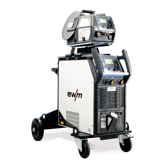
- Page 1 Operating instructions Power source Titan XQ 400 AC puls D 099-005607-EW501 Observe additional system documents! 20.11.2020...
- Page 2 +49 2680 181-0. A list of authorised sales partners can be found at www.ewm-group.com/en/specialist-dealers. Liability relating to the operation of this equipment is restricted solely to the function of the equipment. No other form of liability, regardless of type, shall be accepted.
-
Page 3: Table Of Contents
Contents Notes on using these operating instructions Contents 1 Contents ............................3 2 For your safety ..........................5 Notes on using these operating instructions ................5 Explanation of icons ....................... 6 Safety instructions ........................7 Transport and installation ....................10 3 Intended use .......................... - Page 4 8 Technical data..........................56 Dimensions and weighte ...................... 56 Welding torch cooling system ....................57 Performance data ......................... 58 8.3.1 Titan XQ 400 AC puls D ..................58 9 Accessories ..........................59 General accessories ......................59 7-pole remote control ......................59 9.2.1 Extension cable ....................
-
Page 5: For Your Safety
For your safety Notes on using these operating instructions For your safety Notes on using these operating instructions DANGER Working or operating procedures which must be closely observed to prevent imminent serious and even fatal injuries. • Safety notes include the "DANGER" keyword in the heading with a general warning symbol. •... -
Page 6: Explanation Of Icons
For your safety Explanation of icons Explanation of icons Symbol Description Symbol Description Indicates technical aspects which the u- Activate and release / Tap / Tip ser must observe. Switch off machine Release Switch on machine Press and hold Switch Incorrect / Invalid Turn Correct / Valid... -
Page 7: Safety Instructions
For your safety Safety instructions Safety instructions WARNING Risk of accidents due to non-compliance with the safety instructions! Non-compliance with the safety instructions can be fatal! • Carefully read the safety instructions in this manual! • Observe the accident prevention regulations and any regional regulations! •... - Page 8 For your safety Safety instructions WARNING Risk of injury due to radiation or heat! Arc radiation can lead to skin and eye injuries. Contact with hot workpieces and sparks can lead to burns. • Use hand shield or welding helmet with the appropriate safety level (depends on the appli- cation).
- Page 9 For your safety Safety instructions CAUTION Smoke and gases! Smoke and gases can lead to breathing difficulties and poisoning. In addition, solvent vapour (chlorinated hydrocarbon) may be converted into poisonous phosgene due to the ultraviolet radiation of the arc! • Ensure that there is sufficient fresh air! •...
-
Page 10: Transport And Installation
For your safety Transport and installation CAUTION Obligations of the operator! The respective national directives and laws must be complied with when operating the machine! • Implementation of national legislation relating to framework directive 89/391/EEC on the int- roduction of measures to encourage improvements in the safety and health of workers at work and associated individual guidelines. - Page 11 For your safety Transport and installation CAUTION Risk of accidents due to supply lines! During transport, attached supply lines (mains leads, control cables, etc.) can cause risks, e.g. by causing connected machines to tip over and injure persons! • Disconnect all supply lines before transport! Risk of tipping! There is a risk of the machine tipping over and injuring persons or being damaged itself during movement and set up.
-
Page 12: Intended Use
Phoenix XQ / XQ C Taurus XQ / XQ C Aluminium welding Documents which also apply 3.3.1 Warranty For more information refer to the "Warranty registration" brochure supplied and our information regarding warranty, maintenance and testing at www.ewm-group.com! 099-005607-EW501 20.11.2020... -
Page 13: Declaration Of Conformity
Intended use Documents which also apply 3.3.2 Declaration of Conformity This product corresponds in its design and construction to the EU directives listed in the decla- ration. The product comes with a relevant declaration of conformity in the original. The manufacturer recommends carrying out the safety inspection according to national and in- ternational standards and guidelines every 12 months. -
Page 14: Part Of The Complete Documentation
Intended use Documents which also apply 3.3.6 Part of the complete documentation This document is part of the complete documentation and valid only in combination with all other parts of these instructions! Read and observe the operating instructions for all system components, especially the safety instructions! The illustration shows a general example of a welding system. -
Page 15: Machine Description - Quick Overview
Machine description – quick overview Machine configuration Machine description – quick overview Machine configuration The following table shows the different design variants (expansion stages) of the device series XQ: Type Figure Transport properties Torch cooling Figure 4-1 099-005607-EW501 20.11.2020... -
Page 16: Front View / Side View From The Right
Machine description – quick overview Front view / side view from the right Front view / side view from the right Figure 4-2 Item Symbol Description WiFi antenna Factory-fit option, (version OW Expert XQ 2.0 WLG) 099-005607-EW501 20.11.2020... - Page 17 Machine description – quick overview Front view / side view from the right Item Symbol Description Main Switch Switching the machine on or off. LED status bar - display of operating status The operating status is indicated by a light guide > see 5.1.11.1 chapter. 7-pole connection socket (digital) For connecting digital accessory components Cooling air outlet...
-
Page 18: Rear View / Side View From Left
Machine description – quick overview Rear view / side view from left Rear view / side view from left Figure 4-3 Item Symbol Description Securing elements for shielding gas cylinder (strap/chain) Cooling air inlet Dirt filter optional > see 6.3.1 chapter 099-005607-EW501 20.11.2020... - Page 19 Machine description – quick overview Rear view / side view from left Item Symbol Description Connection socket, “+” welding current How to connect the accessories depends on the welding procedure. Please observe the connection description for the corresponding welding procedure > see 5 chapter. Connection socket, “-”...
-
Page 20: Design And Function
Design and function Transport and installation Design and function WARNING Risk of injury from electrical voltage! Contact with live parts, e.g. power connections, can be fatal! • Observe the safety information on the first pages of the operating instructions! • Commissioning must be carried out by persons who are specifically trained in handling power sources! •... -
Page 21: Ambient Conditions
Design and function Transport and installation 5.1.3 Ambient conditions T he machine must not be operated in the open air and must only be set up and operated on a suitable, stable and level base! • The operator must ensure that the ground is non-slip and level, and provide sufficient lighting for the place of work. -
Page 22: Welding Torch Cooling System
All information relates to the total hose package length of the complete welding system and presents exemplary configurations (of components of the EWM product portfolio with standard lengths). A straight kink-free installation is to be ensured, taking into account the max. delivery height. -
Page 23: Adding Coolant
Design and function Transport and installation 5.1.6.4 Adding coolant After switching on the machine, the coolant pump runs for a maximum of 2 min. (Filling hose package). If the machine does not detect a sufficient coolant flow during this time, the coolant pump is switched off (protection against damage in dry run). -
Page 24: Notes On The Installation Of Welding Current Leads
Design and function Transport and installation 5.1.7 Notes on the installation of welding current leads • Incorrectly installed welding current leads can cause faults in the arc (flickering). • Lay the workpiece lead and hose package of power sources without HF igniter (MIG/MAG) for as long and as close as possible in parallel. -
Page 25: Stray Welding Currents
Design and function Transport and installation 5.1.8 Stray welding currents WARNING Risk of injury due to stray welding currents! Stray welding currents can destroy protective earth conductors, damage machines and electronic devices and cause overheating of components, leading to fire. •... -
Page 26: Pressure Regulator Connection
Design and function Transport and installation 5.1.9.1 Pressure regulator connection Figure 5-7 Item Symbol Description Pressure regulator Output side of the pressure regulator Shielding gas cylinder Cylinder valve • Before connecting the pressure regulator to the gas cylinder, open the cylinder valve briefly to blow out any dirt. -
Page 27: 5.1.10 Mains Connection
Design and function Transport and installation 5.1.10 Mains connection DANGER Hazards caused by improper mains connection! An improper mains connection can cause injuries or damage property! • The connection (mains plug or cable), the repair or voltage adjustment of the device must be carried out by a qualified electrician in accordance with the respective local laws or nati- onal regulations! •... -
Page 28: 5.1.11.1 Led Status Bar - Display Of Operating Status
Design and function Transport and installation 5.1.11.1 LED status bar - display of operating status A light guide on the front of the housing (LED status bar) shows the user the current operating status of the device. Colour of the LED status bar Operating status white (change: light/dark) Booting (switching on up to welding readiness) -
Page 29: Mig/Mag Welding
Design and function MIG/MAG welding MIG/MAG welding 5.2.1 Connecting the intermediate hose package to the power source Figure 5-10 Item Symbol Description Wire feed unit Intermediate hose package 14-pole connection socket Wire feeder control cable connection Intermediate hose package strain relief > see 5.2.1.1 chapter Connection socket, “+”... -
Page 30: Intermediate Hose Package Strain Relief
Design and function MIG/MAG welding • Insert the hose package end of the intermediate hose package from the outside through the strain re- lief of intermediate hose package and then lock by turning to the right. • Insert the control cable through the recess in the gas cylinder bracket, insert the cable plug into the into the connection socket (14-pole) and secure with crown nut (the plug can only be inserted into the connection socket in one position). -
Page 31: Locking The Strain Relief
Design and function MIG/MAG welding 5.2.1.3 Locking the strain relief EWM intermediate hose package Figure 5-12 5.2.2 Connection for workpiece lead Figure 5-13 Item Symbol Description Connection socket, “–” welding current Workpiece lead connection Workpiece • Insert the plug on the workpiece lead into the "-" welding current connection socket and lock. -
Page 32: Setting The Shielding Gas Volume (Gas Test)/Rinse Hose Package
Design and function MIG/MAG welding 5.2.3 Setting the shielding gas volume (gas test)/rinse hose package • Shielding gas supply as described in chapter Transport and positioning > see 5.1.9 chapter. • Slowly open the gas cylinder valve. • Open the pressure regulator. •... -
Page 33: Tig Welding
Design and function TIG welding TIG welding 5.3.1 Connecting the intermediate hose package to the power source TIG combi welding torches are connected to wire feed unit and power source. The welding current for the intermediate hose package must be connected to the welding current connection (-) at the rear of the unit! Figure 5-14 Item Symbol... -
Page 34: Intermediate Hose Package Strain Relief
Possible attachment points Figure 5-15 Item Symbol Description Intermediate hose package strain relief For wire feeder 1 Intermediate hose package Intermediate hose package strain relief For wire feeder 2 5.3.1.3 Locking the strain relief EWM intermediate hose package Figure 5-16 099-005607-EW501 20.11.2020... -
Page 35: Connection For Workpiece Lead
Design and function TIG welding 5.3.2 Connection for workpiece lead Figure 5-17 Item Symbol Description Connection socket, "+" welding current • TIG welding: Workpiece connection Workpiece • Insert the cable plug on the work piece lead into the "+" welding current connection socket and lock by turning to the right. -
Page 36: Mma Welding
Design and function MMA welding MMA welding 5.4.1 Connecting the electrode holder and workpiece lead CAUTION Risk of crushing and burns! When changing stick electrodes there is a risk of crushing and burns! • Wear appropriate and dry protective gloves. •... -
Page 37: Interfaces For Automation
Design and function Interfaces for automation Interfaces for automation WARNING Do not carry out any unauthorised repairs or modifications! To avoid injury and equipment damage, the unit must only be repaired or modified by specialist, skilled persons! The warranty becomes null and void in the event of unauthorised interference. •... -
Page 38: Rint X12 Robot Interface
Windows PC Component identification These accessory components can be retrofitted as an option > see 9 chapter. Bar codes predefined in ewm Xnet are recorded with a manual scanner. Component data are retrieved and displayed in the control. 099-005607-EW501 20.11.2020... -
Page 39: Network Connection
Design and function Network connection Network connection This accessory component is only available as a “factory-fit option”. The network connection allows the integration of the product into an existing network and exchanging data using the quality-management software Xnet. Some features of the software: •... -
Page 40: Maintenance, Care And Disposal
Maintenance, care and disposal General Maintenance, care and disposal General WARNING Incorrect maintenance, testing and repair! Maintenance, testing and repair of the machine may only be carried out by skilled and qualified personnel. A qualified person is one who, because of his or her training, know- ledge and experience, is able to recognise the dangers that can occur while testing welding power sources as well as possible subsequent damage, and who is able to im- plement the required safety procedures. -
Page 41: Explanation Of Icons
Maintenance, care and disposal Explanation of icons Explanation of icons Person Welder / operator Service staff / expert, qualified person Test Visual inspection Functional check Period, interval One-shift operation Multi-shift operation every 8 hours Daily Weekly Monthly Every 6 months Annually 099-005607-EW501 20.11.2020... -
Page 42: Maintenance Schedule
Maintenance, care and disposal Maintenance schedule Maintenance schedule Maintenance step Only people certified as inspectors or repairers may carry out the rele- vant work step due to their training! Non-applicable checkpoints are o- mitted. • Check and clean the welding torch. Deposits in the torch can cause short circuits and have a negative impact on the welding result, ulti- mately causing damage to the welding torch! •... -
Page 43: Dirt Filter
Maintenance, care and disposal Maintenance schedule 6.3.1 Dirt filter When using a dirt filter, the cooling air throughput is reduced and the duty cycle of the machine is reduced as a result. The duty cycle decreases with the increasing contamination of the filter. The dirt filter must be remove at regular intervals and cleaned by blowing out with compressed air (depending on the level of soiling). -
Page 44: Coolant Error
Maintenance, care and disposal Maintenance schedule 6.3.2 Coolant error Observe all instructions for handling, use and disposal of torch coolant > see 5.1.6 chapter. Figure 6-3 • Switch off the machine and disconnect the mains plug. Position a suitable collecting container under the drain plug of the coolant tank. - Page 45 Insert the cleaned filter screen into the filler neck and screw the drain plug with seal back into the tank. • Fill the tank with original EWM coolant up to the maximum level. After filling, refit the tank cap and vent the coolant circuit > see 7.4 chapter.
-
Page 46: Heat Exchanger (Torch Cooling)
Maintenance, care and disposal Maintenance schedule 6.3.3 Heat exchanger (torch cooling) WARNING Risk of injury due to insufficient training! An appropriate training is necessary for the following maintenance steps to avoid inju- ries. • This maintenance step may only be carried out by trained and authorized specialist staff. •... -
Page 47: Power Source (Inverter)
Maintenance, care and disposal Maintenance schedule 6.3.4 Power source (inverter) WARNING Risk of injury due to insufficient training! An appropriate training is necessary for the following maintenance steps to avoid inju- ries. • This maintenance step may only be carried out by trained and authorized specialist staff. •... -
Page 48: Annual Test (Inspection And Testing During Operation)
• Information about returning used equipment or about collections can be obtained from the respective municipal administration office. • In addition to this, returns are also possible throughout Europe via EWM sales partners. 099-005607-EW501 20.11.2020... -
Page 49: Rectifying Faults
Rectifying faults Error messages (power source) Rectifying faults All products are subject to rigorous production checks and final checks. If, despite this, something fails to work at any time, please check the product using the following flowchart. If none of the fault rectification procedures described leads to the correct functioning of the product, please inform your authorised dea- ler. - Page 50 Rectifying faults Error messages (power source) Category Error Possible cause Remedy Air in the coolant circuit Vent coolant circuit Hose package not completely Switch machine off / on (pump filled with coolant runs for 2 min) Operation with gas-cooled Connect coolant feed and welding torch coolant return (insert hose bridge);...
- Page 51 Rectifying faults Error messages (power source) Category Error Possible cause Remedy VRD error Open circuit voltage reduction if necessary, disconnect ex- error ternal machine from the welding circuit; inform Service WF excess cur- Overcurrent detection on wire Do not place the liner in tight rent feeder radii;...
-
Page 52: Warnings
Rectifying faults Warnings Warnings Depending on the display options of the machine display, a warning message is displayed as follows: Display type - machine control Display Graphic display two 7-segment displays one 7-segment display The cause of the warning is indicated by a corresponding warning number (see table). •... -
Page 53: Checklist For Rectifying Faults
Rectifying faults Checklist for rectifying faults Checklist for rectifying faults The correct machine equipment for the material and process gas in use is a fundamental requirement for perfect operation! Legend Symbol Description Fault/Cause Remedy Functional errors Mains fuse triggers - unsuitable mains fuse Set up recommended mains fuse >... -
Page 54: Vent Coolant Circuit
Rectifying faults Vent coolant circuit Wire feed problems Wire feed roll holder is worn (wire feed rolls must be firmly seated on their holders and must not have any play) Replace wire feed roll holder (092-002960-E0000) Contact tip blocked Clean, spray with anti-spatter spray and replace if necessary ... -
Page 55: Fixing The Pump Shaft (Coolant Circuit)
Rectifying faults Fixing the pump shaft (coolant circuit) Fixing the pump shaft (coolant circuit) Continuing non-use and impurities in the coolant may result in the the coolant pump not being in proper working order. Figure 7-3 • Switch off machine at the main switch. •... -
Page 56: Technical Data
Technical data Dimensions and weighte Technical data Performance specifications and guarantee only in connection with original spare and replacement parts! Dimensions and weighte F06R1/R2 F06RS F06P Dimensions (l x b x h) inch inch inch 1152 45.3 33.6 33.6 27.0 23.2 15.7 38.4... -
Page 57: Welding Torch Cooling System
Technical data Welding torch cooling system Welding torch cooling system Torch cooling F06W F06WRF Cooling capacity at 1 l/min (+25°C/77°F) 1.5 KW Max. flow rate 5 l/min 20 l/min 1.3 gal./min 5.2 gal./min max. delivery height 35 m 45 m 115 ft. -
Page 58: Performance Data
Technical data Performance data Performance data 8.3.1 Titan XQ 400 AC puls D MIG/MAG Welding current (I 5 A to 400 A Welding voltage according to standard (U 14,3 V to 34,0 V 20,2 V to 36,0 V 10,2 V to 26,0 V Duty cycle DC at 40°... -
Page 59: Accessories
Accessories General accessories Accessories Performance-dependent accessories like torches, workpiece leads, electrode holders or intermediate hose packages are available from your authorised dealer. General accessories Type Designation Item no. KLF-L1-L2-L3-PE Label of mains cable 094-023697-00000 DM 842 Ar/CO2 230bar 30l D Pressure regulator with manometer 394-002910-00030 32A 5POLE/CEE... -
Page 60: Options
Accessories Options Options Type Designation Item no. ON PS F06 1D01 Pivot support for a wire feeder 092-003330-00000 ON PS F06 1D02 Pivot support for an IC wire feeder 092-003332-00000 ON PS F06 2D01 Transport support for two wire feeders 092-003331-00000 ON PS EXT D01 Retrofit set: Extension turning mandrel, for holding a... -
Page 61: Appendix
Appendix Searching for a dealer Appendix 10.1 Searching for a dealer Sales & service partners www.ewm-group.com/en/specialist-dealers "More than 400 EWM sales partners worldwide" 099-005607-EW501 20.11.2020...
Need help?
Do you have a question about the Titan XQ 400 AC puls D and is the answer not in the manual?
Questions and answers