EWM Tetrix 200 MV Comfort 2.0 puls 8P TM Operating Instructions Manual
Hide thumbs
Also See for Tetrix 200 MV Comfort 2.0 puls 8P TM:
- Operating instructions manual (38 pages)

Related Manuals for EWM Tetrix 200 MV Comfort 2.0 puls 8P TM


Summary of Contents for EWM Tetrix 200 MV Comfort 2.0 puls 8P TM
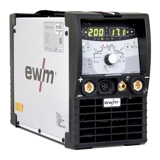
- Page 1 Operating instructions Power source Tetrix 200 DC Smart 2.0 puls TM Tetrix 200 DC Comfort 2.0 puls TM Tetrix 200 MV Comfort 2.0 puls 8P TM 099-000261-EW501 Observe additional system documents! 21.06.2018...
- Page 2 +49 2680 181-0. A list of authorised sales partners can be found at www.ewm-group.com/en/specialist-dealers. Liability relating to the operation of this equipment is restricted solely to the function of the equipment.
-
Page 3: Table Of Contents
Contents Notes on the use of these operating instructions Contents 1 Contents ..............................3 2 For your safety ............................5 Notes on the use of these operating instructions ................5 Explanation of icons ........................6 Part of the complete documentation ....................7 Safety instructions .......................... - Page 4 Contents Notes on the use of these operating instructions 9 Accessories ............................34 Remote controls and accessories ....................34 Options ............................34 Transport systems ........................34 General accessories ........................34 Computer communication ......................34 10 Appendix A ............................35 10.1 Searching for a dealer ........................35 099-000261-EW501 21.06.2018...
-
Page 5: For Your Safety
For your safety Notes on the use of these operating instructions For your safety Notes on the use of these operating instructions DANGER Working or operating procedures which must be closely observed to prevent imminent serious and even fatal injuries. •... -
Page 6: Explanation Of Icons
For your safety Explanation of icons Explanation of icons Symbol Description Symbol Description Indicates technical aspects which the Activate and release / Tap / Tip user must observe. Switch off machine Release Switch on machine Press and hold Switch Incorrect / Invalid Turn Numerical value –... -
Page 7: Part Of The Complete Documentation
For your safety Part of the complete documentation Part of the complete documentation These operating instructions are part of the complete documentation and valid only in combination with all other parts of these instructions! Read and observe the operating instructions for all system components, especially the safety instructions! The illustration shows a general example of a welding system. - Page 8 For your safety Safety instructions WARNING Hazard when interconnecting multiple power sources! If a number of power sources are to be connected in parallel or in series, only a technical specialist may interconnect the sources as per standard IEC 60974-9:2010: Installation and use and German Accident Prevention Regulation BVG D1 (formerly VBG 15) or country-specific regulations.
- Page 9 For your safety Safety instructions CAUTION Smoke and gases! Smoke and gases can lead to breathing difficulties and poisoning. In addition, solvent vapour (chlorinated hydrocarbon) may be converted into poisonous phosgene due to the ultraviolet radiation of the arc! • Ensure that there is sufficient fresh air! •...
-
Page 10: Transport And Installation
For your safety Transport and installation Obligations of the operator! The respective national directives and laws must be complied with when operating the machine! • Implementation of national legislation relating to framework directive 89/391/EEC on the introduction of measures to encourage improvements in the safety and health of workers at work and associated individual guidelines. - Page 11 For your safety Transport and installation The units are designed for operation in an upright position! Operation in non-permissible positions can cause equipment damage. • Only transport and operate in an upright position! Accessory components and the power source itself can be damaged by incorrect connection! •...
-
Page 12: Intended Use
3.2.1 Warranty For more information refer to the "Warranty registration" brochure supplied and our information regarding warranty, maintenance and testing at www.ewm-group.com! 3.2.2 Declaration of Conformity The labelled product complies with the following EC directives in terms of its design and construction: •... -
Page 13: Machine Description - Quick Overview
Machine description – quick overview Front view / rear view Machine description – quick overview Front view / rear view Figure 4-1 099-000261-EW501 21.06.2018... - Page 14 Machine description – quick overview Front view / rear view Item Symbol Description Carrying strap > see 5.1.4 chapter Machine control, see the relevant control operating instructions Connection socket, welding torch control cable > see 5.2.1.1 chapter Connection socket, “+” welding current How to connect the accessories depends on the welding procedure.
-
Page 15: Design And Function
Design and function Transport and installation Design and function WARNING Risk of injury from electrical voltage! Contact with live parts, e.g. power connections, can be fatal! • Observe the safety information on the first pages of the operating instructions! • Commissioning must be carried out by persons who are specifically trained in handling power sources! •... -
Page 16: Workpiece Lead, General
Design and function Transport and installation 5.1.3 Workpiece lead, general CAUTION Risk of burning due to incorrect welding current connection! If the welding current plugs (machine connections) are not locked or if the workpiece connection is contaminated (paint, corrosion), these connections and leads can heat up and cause burns when touched! •... -
Page 17: Notes On The Installation Of Welding Current Leads
Design and function Transport and installation 5.1.5 Notes on the installation of welding current leads • Incorrectly installed welding current leads can cause faults in the arc (flickering). • Lay the workpiece lead and hose package of power sources without HF igniter (MIG/MAG) for as long and as close as possible in parallel. -
Page 18: Stray Welding Currents
Design and function Transport and installation 5.1.6 Stray welding currents WARNING Risk of injury due to stray welding currents! Stray welding currents can destroy protective earth conductors, damage machines and electronic devices and cause overheating of components, leading to fire. •... -
Page 19: Mains Configuration
Design and function TIG welding 5.1.7.1 Mains configuration The machine may only be connected to a one-phase system with two conductors and an earthed neutral conductor. Figure 5-6 Legend Item Designation Colour code Outer conductor brown Neutral conductor blue Protective conductor green-yellow •... -
Page 20: Connection Assignment, Welding Torch Control Cable
Design and function TIG welding • Insert the welding current plug on the welding torch into the welding current connection socket and lock by turning to the right. • Remove yellow protective cap on G¼ connecting nipple. • Screw welding torch shielding gas connection tightly onto the G¼" connection nipple. •... -
Page 21: Connecting The Shielding Gas Supply
Design and function MMA welding 5.2.2.1 Connecting the shielding gas supply Figure 5-9 Item Symbol Description Pressure regulator Shielding gas cylinder Output side of the pressure regulator Cylinder valve • Before connecting the pressure regulator to the gas cylinder, open the cylinder valve briefly to blow out any dirt. - Page 22 Design and function MMA welding Figure 5-10 Item Symbol Description Electrode holder Connection socket, “-” welding current Workpiece lead or electrode holder connection Workpiece Connection socket for "+" welding current Electrode holder or workpiece lead connection Connecting nipple G¼, shielding gas connection Polarity depends on the instructions from the electrode manufacturer given on the electrode packaging.
-
Page 23: Remote Control
Design and function Remote control Remote control Remote controls are used for the remote operation of various machine functions (see operating instructions for remote control). The remote control connection is designed with 19 pins. Figure 5-11 Item Symbol Description Connection socket, 19-pole Remote control connection Remote control •... -
Page 24: Pc Interface
Design and function PC interface PC interface PC 300 welding parameter software Set all welding parameters on the PC and simply transfer to one or more welding machines (accessory, set consisting of software, interface, connection leads) • Manage up to 510 JOBs •... -
Page 25: Remote Control Connection Socket, 19-Pole
Design and function Interfaces for automation 5.6.1 Remote control connection socket, 19-pole Figure 5-13 Pos. Signal shape Designation Output Connection for cable screen (PE) Output Current flows signal I>0, galvanically isolated (max. +- 15V/100mA) Output Reference voltage for potentiometer 10V (max. 10mA) Input Control value specification for main current, 0-10V (0V = I , 10V =... -
Page 26: Maintenance, Care And Disposal
Maintenance, care and disposal General Maintenance, care and disposal General DANGER Risk of injury due to electrical voltage after switching off! Working on an open machine can lead to fatal injuries! Capacitors are loaded with electrical voltage during operation. Voltage remains present for up to four minutes after the mains plug is removed. -
Page 27: Maintenance Work, Intervals
A periodic test according to IEC 60974-4 "Periodic inspection and test" has to be carried out. In addition to the regulations on testing given here, the relevant local laws and regulations must also be observed. For more information refer to the "Warranty registration" brochure supplied and our information regarding warranty, maintenance and testing at www.ewm-group.com! 099-000261-EW501 21.06.2018... -
Page 28: Disposing Of Equipment
• Information about returning used equipment or about collections can be obtained from the respective municipal administration office. • In addition to this, returns are also possible throughout Europe via EWM sales partners. 099-000261-EW501 21.06.2018... -
Page 29: Rectifying Faults
Rectifying faults Checklist for rectifying faults Rectifying faults All products are subject to rigorous production checks and final checks. If, despite this, something fails to work at any time, please check the product using the following flowchart. If none of the fault rectification procedures described leads to the correct functioning of the product, please inform your authorised dealer. - Page 30 Rectifying faults Checklist for rectifying faults Unstable arc Material inclusions in the tungsten electrode due to contact with filler material or workpiece Regrind or replace the tungsten electrode Incompatible parameter settings Check settings and correct if necessary Pore formation ...
-
Page 31: Technical Data
Technical data Tetrix 200 Technical data Performance specifications and guarantee only in connection with original spare and replacement parts! Tetrix 200 Welding current (I 5 A up to 200 A 5 A up to 150 A Welding voltage according to Standard 10,2 V up to 18,0 V 20,2 V up to 26,0 V Duty cycle at 40°... -
Page 32: Tetrix 200 Mv
Technical data Tetrix 200 MV Tetrix 200 MV 8.2.1 Netzanschlussspannung 115 V Welding current (I 5 A up to 150 A 5 A up to 110 A Welding voltage according to Standard 10,2 V up to 16,0 V 20,2 V up to 24,4 V Duty cycle at 40°... -
Page 33: Netzanschlussspannung 230 V
Technical data Tetrix 200 MV 8.2.2 Netzanschlussspannung 230 V Welding current (I 5 A up to 200 A 5 A up to 150 A Welding voltage according to Standard 10,2 V up to 18,0 V 20,2 V up to 26,0 V Duty cycle at 40°... - Page 34 Accessories Remote controls and accessories Accessories Performance-dependent accessories like torches, workpiece leads, electrode holders or intermediate hose packages are available from your authorised dealer. Remote controls and accessories Type Designation Item no. RTF1 19POL 5 M Foot-operated remote control current with 094-006680-00000 connection cable RT1 19POL...
- Page 35 Appendix A Searching for a dealer Appendix A 10.1 Searching for a dealer Sales & service parteners www.ewm-group.com/en/specialist-dealers "More than 400 EWM sales partners worldwide" 099-000261-EW501 21.06.2018...
Need help?
Do you have a question about the Tetrix 200 MV Comfort 2.0 puls 8P TM and is the answer not in the manual?
Questions and answers