
Subscribe to Our Youtube Channel
Related Manuals for EWM Tetrix 200 DC Smart 2.0 puls TM


Summary of Contents for EWM Tetrix 200 DC Smart 2.0 puls TM
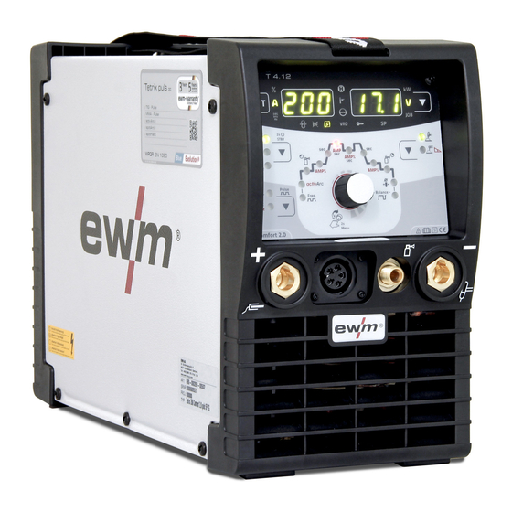
- Page 1 Operating instructions Power source Tetrix 200 DC Smart 2.0 puls TM Tetrix 200 DC Comfort 2.0 puls TM Tetrix 200 MV Comfort 2.0 puls 8P TM 099-000261-EW501 Observe additional system documents! 23.9.2022...
- Page 2 +49 2680 181-0. A list of authorised sales partners can be found at www.ewm-group.com/en/specialist-dealers. Liability relating to the operation of this equipment is restricted solely to the function of the equipment. No other f orm of liability, regardless of type, shall be accepted.
-
Page 3: Table Of Contents
Contents Notes on using these operating instructions Contents 1 Contents........................3 2 For your safety......................5 Notes on using these operating instructions ............... 5 Explanation of icons ....................6 Saf ety instructions ....................7 Transport and installation ..................10 3 Intended use ........................12 Applications......................12 Documents which also apply ...................12 3.2.1... - Page 4 Contents Notes on using these operating instructions 9 Accessories.........................36 Transport system ....................36 Remote controls and accessories ................36 9.2.1 Connection cables ...................36 9.2.2 Extension cable ..................36 Options........................36 Tetrix 200 Comfort puls ..................36 General accessories ....................36 Computer communication ..................37 10 Appendix ........................38 10.1 Searching for a dealer....................38 099-000261-EW501 23.9.2022...
-
Page 5: For Your Safety
For your safety Notes on using these operating instructions For your safety Notes on using these operating instructions DANGER Working or operating procedures which must be closely observed to prevent imminent serious and even fatal injuries. • Saf ety notes include the "DANGER" keyword in the heading with a general warning symbol. •... -
Page 6: Explanation Of Icons
For your safety Explanation of icons Explanation of icons Symbol Description Symbol Description Indicates technical aspects which the Activate and release / Tap / Tip user must observe. Switch off machine Release Switch on machine Press and hold Incorrect / Invalid Switch Correct / Valid Turn... -
Page 7: Safety Instructions
For your safety Saf ety instructions Safety instructions WARNING Risk of accidents due to non-compliance with the safety instructions! Non-compliance with the safety instructions can be fatal! • Caref ully read the safety instructions in this manual! • Observe the accident prevention regulations and any regional regulations! •... - Page 8 For your safety Saf ety instructions WARNING Risk of injury due to improper clothing! During arc welding, radiation, heat and voltage are sources of risk that cannot be avoided. The user has to be equipped with the complete personal protective equipment at all times.
- Page 9 For your safety Saf ety instructions CAUTION Smoke and gases! Smoke and gases can lead to breathing difficulties and poisoning. In addition, solvent vapour (chlorinated hydrocarbon) may be converted into poisonous phosgene due to the ultraviolet radiation of the arc! •...
-
Page 10: Transport And Installation
For your safety Transport and installation CAUTION Obligations of the operator! The respective national directives and laws must be complied with when operating the machine! • Implementation of national legislation relating to framework directive 89/391/EEC on the int- roduction of measures to encourage improvements in the safety and health of workers at work and associated individual guidelines. - Page 11 For your safety Transport and installation CAUTION Risk of accidents due to supply lines! During transport, attached supply lines (mains leads, control cables, etc.) can cause risks, e.g. by causing connected machines to tip over and injure persons! • Disconnect all supply lines before transport! Risk of tipping! There is a risk of the machine tipping over and injuring persons or being damaged itself during movement and set up.
-
Page 12: Intended Use
3.2.1 Warranty For more information refer to the "Warranty registration" brochure supplied and our information regarding warranty, maintenance and testing at www.ewm-group.com! 3.2.2 Declaration of Conformity This product corresponds in its design and construction to the EU directives listed in the decla- ration. -
Page 13: Part Of The Complete Documentation
Intended use Documents which also apply 3.2.6 Part of the complete documentation This document is part of the complete documentation and valid only in combination with all other parts of these instructions! Read and observe the operating instructions for all system components, especially the safety instructions! The illustration shows a general example of a welding system. -
Page 14: Machine Description - Quick Overview
Machine description – quick overview Front view / rear view Machine description – quick overview Front view / rear view Figure 4-1 099-000261-EW501 23.9.2022... - Page 15 Machine description – quick overview Front view / rear view Item Symbol Description Carrying strap > see 5.1.4.1 chapter Machine control (see the relevant control operating instructions) Connection socket (welding torch control cable) > see 5.2.1.1 chapter Connection socket, “+” welding current How to connect the accessories depends on the welding procedure.
-
Page 16: Design And Function
Design and function Transport and installation Design and function WARNING Risk of injury from electrical voltage! Contact with live parts, e.g. power connections, can be fatal! • Observe the safety information on the first pages of the operating instructions! • Commissioning must be carried out by persons who are specifically trained in handling power sources! •... -
Page 17: Workpiece Lead, General
Design and function Transport and installation 5.1.3 Workpiece lead, general CAUTION Risk of burning due to incorrect welding current connection! If the welding current plugs (machine connections) are not locked or if the workpiece connection is contaminated (paint, corrosion), these connections and leads can heat up and cause burns when touched! •... -
Page 18: Notes On The Installation Of Welding Current Leads
Design and function Transport and installation 5.1.5 Notes on the installation of welding current leads • Incorrectly installed welding current leads can cause faults in the arc (flickering). • Lay the workpiece lead and hose package of power sources without HF igniter (MIG/MAG) for as long and as close as possible in parallel. -
Page 19: Stray Welding Currents
Design and function Transport and installation 5.1.6 Stray welding currents WARNING Risk of injury due to stray welding currents! Stray welding currents can destroy protective earth conductors, damage machines and electronic devices and cause overheating of components, leading to fire. •... -
Page 20: Mains Connection
Design and function Transport and installation 5.1.7 Mains connection DANGER Hazards caused by improper mains connection! An improper mains connection can cause injuries or damage property! • The connection (mains plug or cable), the repair or voltage adjustment of the device must be carried out by a qualified electrician in accordance with the respective local laws or nati- onal regulations! •... -
Page 21: Tig Welding
Design and function TIG welding TIG welding 5.2.1 Welding torch and workpiece line connection Prepare welding torch according to the welding task in hand (see operating instructions for the torch). Figure 5-7 Item Symbol Description Welding torch Welding torch hose package Connection socket, "-"... -
Page 22: Control Lead Connection
Design and function TIG welding 5.2.1.1 Control lead connection TIG welding machines are equipped ex works with a dedicated connection socket for the welding torch control cable (5- or 8-pole). As mobile machines offer more free space, they may even feature two control cable connection sockets. -
Page 23: Connecting The Shielding Gas Supply
Design and function TIG welding 5.2.2.1 Connecting the shielding gas supply Figure 5-9 Item Symbol Description Pressure regulator Output side of the pressure regulator Shielding gas cylinder Cylinder valve • Bef ore connecting the pressure regulator to the gas cylinder, open the cylinder valve briefly to blow out any dirt. -
Page 24: Mma Welding
Design and function MMA welding MMA welding 5.3.1 Connecting the electrode holder and workpiece lead CAUTION Risk of crushing and burns! When changing stick electrodes there is a risk of crushing and burns! • Wear appropriate and dry protective gloves. •... -
Page 25: Remote Control
Design and function Remote control Remote control Remote controls are used for the remote operation of various machine functions (see operating instruc- tions for remote control). The remote control connection is designed with 19 pins. Figure 5-11 Item Symbol Description Connection socket, 19-pole Remote control connection Remote control... -
Page 26: Connection
Design and function Interf aces for automation 5.5.1 Connection Equipment damage or faults may occur if the PC is connected incorrectly! Not using the SECINT X10USB interface results in equipment damage or faults in signal trans- mission. The PC may be destroyed due to high frequency ignition pulses. •... -
Page 27: Remote Control Connection Socket, 19-Pole
Design and function Interf aces for automation 5.6.1 Remote control connection socket, 19-pole Figure 5-13 Pos. Pin Signal shape Designation Output Connection for cable screen (PE) Output Current f lows signal I>0, galvanically isolated (max. +- 15V/100mA) Output Ref erence voltage for potentiometer 10V (max. 10mA) Control value specification for main current, 0-10V (0V = I , 10V = Input... -
Page 28: Maintenance, Care And Disposal
Maintenance, care and disposal General Maintenance, care and disposal General DANGER Risk of injury due to electrical voltage after switching off! Working on an open machine can lead to fatal injuries! Capacitors are loaded with electrical voltage during operation. Voltage remains present for up to four minutes after the mains plug is removed. -
Page 29: Maintenance Work, Intervals
A periodic test according to IEC 60974-4 "Periodic inspection and test" has to be carried out. In addition to the regulations on testing given here, the relevant local laws and regulations must also be observed. For more information refer to the "Warranty registration" brochure supplied and our information regarding warranty, maintenance and testing at www.ewm-group.com! 099-000261-EW501 23.9.2022... -
Page 30: Disposing Of Equipment
Inf ormation on returning used equipment or collections can be obtained from the respective municipal administration office. Devices can also be returned to EWM sales partners across Europe. Further inf ormation on the topic of the disposal of electrical and electronic equipment can be found on our website at: https://www.ewm-group.com/de/nachhaltigkeit.html. -
Page 31: Rectifying Faults
Rectifying faults Checklist for rectifying faults Rectifying faults All products are subject to rigorous production checks and final checks. If , despite this, something fails to work at any time, please check the product using the following flowchart. If none of the fault rectification procedures described leads to the correct functioning of the product, please inform your authorised dea- ler. - Page 32 Rectifying faults Checklist for rectifying faults Unstable arc Material inclusions in the tungsten electrode due to contact with filler material or workpiece Regrind or replace the tungsten electrode Incompatible parameter settings Check settings and correct if necessary ...
-
Page 33: Technical Data
Technical data Tetrix 200 Technical data Performance specifications and guarantee only in connection with original spare and replacement parts! Tetrix 200 Welding current (I 5 A to 200 A 5 A to 150 A Welding voltage according to standard (U 10,2 V to 18,0 V 20,2 V to 26,0 V Duty cycle DC at 40°... -
Page 34: Tetrix 200 Mv
Technical data Tetrix 200 MV Tetrix 200 MV 8.2.1 Mains voltage 115 V Welding current (I 5 A to 150 A 5 A to 110 A Welding voltage according to standard (U 10,2 V to 16,0 V 20,2 V to 24,4 V Duty cycle DC at 40°... -
Page 35: Mains Voltage 230 V
Technical data Tetrix 200 MV 8.2.2 Mains voltage 230 V Welding current (I 5 A to 200 A 5 A to 150 A Welding voltage according to standard (U 10,2 V to 18,0 V 20,2 V to 26,0 V Duty cycle DC at 40° C 200 A (25 %) 150 A (35 %) 150 A (60 %) - Page 36 Accessories Transport system Accessories Performance-dependent accessories like torches, workpiece leads, electrode holders or intermediate hose packages are available from your authorised dealer. Transport system Type Designation Item no. Trolly 35-1 Transport vehicle 090-008629-00000 Remote controls and accessories Type Designation Item no. Foot-operated remote control current with connec- RTF1 19POL 5 M 094-006680-00000...
- Page 37 Accessories Computer communication Computer communication Type Designation Item no. PC300.Net welding parameter software kit incl. PC300 XQ Set 090-008777-00000 cable and SECINT X10 USB interface 099-000261-EW501 23.9.2022...
- Page 38 Appendix Searching for a dealer Appendix 10.1 Searching for a dealer Sales & service partners www.ewm-group.com/en/specialist-dealers "More than 400 EWM sales partners worldwide" 099-000261-EW501 23.9.2022...
Need help?
Do you have a question about the Tetrix 200 DC Smart 2.0 puls TM and is the answer not in the manual?
Questions and answers