EWM Tetrix 352 Synergic Operating Instructions Manual
Power source
Hide thumbs
Also See for Tetrix 352 Synergic:
- Operating instructions manual (81 pages) ,
- Operating instructions manual (97 pages)

Related Manuals for EWM Tetrix 352 Synergic


Summary of Contents for EWM Tetrix 352 Synergic
- Page 1 Operating instructions Power source Tetrix 352 Synergic Tetrix 452 Synergic Tetrix 552 Synergic 099-000141-EW501 Observe additional system documents! 22.03.2023...
- Page 2 +49 2680 181-0. A list of authorised sales partners can be found at www.ewm-group.com/en/specialist-dealers. Liability relating to the operation of this equipment is restricted solely to the function of the equipment. No other form of liability, regardless of type, shall be accepted.
-
Page 3: Table Of Contents
Contents Notes on using these operating instructions Contents 1 Contents ............................3 2 For your safety ..........................6 Notes on using these operating instructions ................6 Explanation of icons ....................... 7 Safety instructions ........................8 Transport and installation ....................11 3 Intended use .......................... - Page 4 Contents Notes on using these operating instructions 5.4.2.2 Liftarc ..................... 40 5.4.2.3 Automatic cut-out .................. 40 5.4.3 Optimising the ignition characteristics for pure tungsten electrodes ....41 5.4.3.1 Tungsten balling function ..............41 5.4.4 Operating modes (functional sequences) ............. 42 5.4.4.1 Explanation of symbols .................
- Page 5 Contents Notes on using these operating instructions 8 Technical data ..........................82 Tetrix 352 ..........................82 Tetrix 452 ..........................83 Tetrix 552 ..........................84 9 Accessories ..........................85 General accessories ......................85 Connection cables, connection sockets................85 Options ..........................85 Transport system .........................
-
Page 6: For Your Safety
For your safety Notes on using these operating instructions For your safety Notes on using these operating instructions DANGER Working or operating procedures which must be closely observed to prevent imminent serious and even fatal injuries. • Safety notes include the "DANGER" keyword in the heading with a general warning symbol. •... -
Page 7: Explanation Of Icons
For your safety Explanation of icons Explanation of icons Symbol Description Symbol Description Indicates technical aspects which the Activate and release / Tap / Tip user must observe. Switch off machine Release Switch on machine Press and hold Incorrect / Invalid Switch Correct / Valid Turn... -
Page 8: Safety Instructions
For your safety Safety instructions Safety instructions WARNING Risk of accidents due to non-compliance with the safety instructions! Non-compliance with the safety instructions can be fatal! • Carefully read the safety instructions in this manual! • Observe the accident prevention regulations and any regional regulations! •... - Page 9 For your safety Safety instructions WARNING Risk of injury due to improper clothing! During arc welding, radiation, heat and voltage are sources of risk that cannot be avoided. The user has to be equipped with the complete personal protective equipment at all times.
- Page 10 For your safety Safety instructions CAUTION Smoke and gases! Smoke and gases may lead to shortness of breath and poisoning! The ultraviolet radia- tion of the arc may also convert solvent vapours (chlorinated hydrocarbon) into poiso- nous phosgene. • Ensure sufficient fresh air! •...
-
Page 11: Transport And Installation
For your safety Transport and installation CAUTION Obligations of the operator! The respective national directives and laws must be complied with when operating the machine! • Implementation of national legislation relating to framework directive 89/391/EEC on the in- troduction of measures to encourage improvements in the safety and health of workers at work and associated individual guidelines. - Page 12 For your safety Transport and installation CAUTION Risk of accidents due to supply lines! During transport, attached supply lines (mains leads, control cables, etc.) can cause risks, e.g. by causing connected machines to tip over and injure persons! • Disconnect all supply lines before transport! Risk of tipping! There is a risk of the machine tipping over and injuring persons or being damaged itself during movement and set up.
-
Page 13: Intended Use
3.4.1 Warranty For more information refer to the "Warranty registration" brochure supplied and our information regarding warranty, maintenance and testing at www.ewm-group.com! 3.4.2 Declaration of Conformity This product corresponds in its design and construction to the EU directives listed in the decla- ration. -
Page 14: Service Documents (Spare Parts And Circuit Diagrams)
Intended use Documents which also apply 3.4.4 Service documents (spare parts and circuit diagrams) WARNING No improper repairs and modifications! To prevent injuries and damage to the machine, only competent personnel (authorised service personnel) are allowed to repair or modify the machine. Unauthorised manipulations will invalidate the warranty! •... - Page 15 Intended use Documents which also apply Item Operating instructions Wire feeder, media separation box Options conversion instructions Robot Robot interface Transport pallet Cooling unit, voltage converter, media separation box etc. Power source Control Remote control A.10 Collision sensor A.11 Hot wire power source A.12 Welding torches Complete documentation...
-
Page 16: Machine Description - Quick Overview
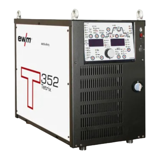
Machine description – quick overview Front view Machine description – quick overview Front view Figure 4-1 099-000141-EW501 22.03.2023... - Page 17 Machine description – quick overview Front view Item Symbol Description Lifting lug > see 5.1.1 chapter Machine control > see 4.2 chapter Cooling air inlet Machine feet Interfaces Optional interface in the extension casing for assembly onto the power source •...
-
Page 18: Machine Control - Operating Elements
Machine description – quick overview Machine control – Operating elements Machine control – Operating elements 4.2.1 Machine control (Mode RC - on) This welding machine is operated in 'RC – on, remote-controlled' mode ex works. RC – on: The machine is controlled via an external interface in this mode. The majority of operating elements on the machine control are deactivated and are used to check the welding data only. -
Page 19: Function Sequence
Machine description – quick overview Machine control – Operating elements Item Symbol Description Welding data display (3-digit) Displays the welding parameters and the corresponding values > see 4.2.3 chapter Display switching button ------- Material thickness display VOLT --- Welding voltage display JOB ----- JOB number display PROG --- Program number display 4.2.1.1... -
Page 20: Machine Control (Mode Rc - Off)
Machine description – quick overview Machine control – Operating elements 4.2.2 Machine control (Mode RC - off) As the plasma welding process is based directly on the TIG welding process, the TIG descriptions are used for plasma welding, with just a few differences. Figure 4-4 Item Symbol Description... -
Page 21: Function Sequence
Machine description – quick overview Machine control – Operating elements Item Symbol Description Pulsing push-button -- TIG automated pulsing (frequency and balance) -------- Signal light lights up in green: Pulsing (thermal pulsing)/MMA pulse welding -------- Signal light lights up in red: kHz pulsing (metallurgical pulsing) Gas test/rinse hose package button >... -
Page 22: Welding Data Display
Machine description – quick overview Machine control – Operating elements Item Symbol Description Signal light Up-slope time (TIG)/hot start time (MMA) Main current (TIG) / pulse current Main current (MMA) I min to I max (1 A increments) I min to I max (1 A increments) Pulse time / slope time from AMP% to AMP / Spot time... -
Page 23: Welding Parameter Setting
Machine description – quick overview Machine control – Operating elements 4.2.4 Welding parameter setting During the welding parameter setting process, the parameter value being set is displayed on the left-hand display. The right-hand display shows the “Factory setting” or a variation of it upwards or downwards. Dis- plays, e.g. -
Page 24: Connection Plan
Machine description – quick overview Connection plan Connection plan RINTX12 BUSINTX11 SPS / CU / ROB digital forceTig Medienbox Tetrix Synergic Cool 82 Figure 4-6 099-000141-EW501 22.03.2023... -
Page 25: Legend
Machine description – quick overview Connection plan 4.3.1 Legend Connection socket, control cable (19-pole) for welding torch Welding current (plus potential, workpiece) Welding current (minus potential) Shielding gas Torch coolant Coolant water inlet Coolant water outlet Supply voltage to the welding machine Interface for automated welding (19-pole) Control cable for the cooling unit (8-pole) Control cable RINT X12, BUSINT X11 (7-pole) -
Page 26: Design And Function
Design and function Transport and installation Design and function WARNING Risk of injury from electrical voltage! Contact with live parts, e.g. power connections, can be fatal! • Observe the safety information on the first pages of the operating instructions! • Commissioning must be carried out by persons who are specifically trained in handling power sources! •... -
Page 27: Machine Cooling
Design and function Transport and installation In operation Temperature range of the ambient air: • -25 °C to +40 °C (-13 °F to 104 °F) Relative humidity: • up to 50 % at 40 °C (104 °F) • up to 90 % at 20 °C (68 °F) Transport and storage Storage in a closed room, temperature range of the ambient air: •... -
Page 28: Notes On The Installation Of Welding Current Leads
Design and function Transport and installation 5.1.5 Notes on the installation of welding current leads • Incorrectly installed welding current leads can cause faults in the arc (flickering). • Lay the workpiece lead and hose package of power sources without HF igniter (MIG/MAG) for as long and as close as possible in parallel. -
Page 29: Stray Welding Currents
Design and function Transport and installation 5.1.6 Stray welding currents WARNING Risk of injury due to stray welding currents! Stray welding currents can destroy protective earth conductors, damage machines and electronic devices and cause overheating of components, leading to fire. •... -
Page 30: Mains Connection
Design and function Transport and installation 5.1.7 Mains connection DANGER Hazards caused by improper mains connection! An improper mains connection can cause injuries or damage property! • The connection (mains plug or cable), the repair or voltage adjustment of the device must be carried out by a qualified electrician in accordance with the respective local laws or na- tional regulations! •... -
Page 31: Shielding Gas Supply (Shielding Gas Cylinder For Welding Machine)
Design and function Transport and installation 5.1.8 Shielding gas supply (shielding gas cylinder for welding machine) WARNING Risk of injury due to improper handling of shielding gas cylinders! Improper handling and insufficient securing of shielding gas cylinders can cause seri- ous injuries! •... -
Page 32: Shielding Gas Hose Connection
Design and function Transport and installation 5.1.9.1 Shielding gas hose connection Figure 5-7 Item Symbol Description Connection thread - G¼" Shielding gas connection (inlet) • Screw the crown nut on the shielding gas lead gastight to the connecting thread (G¼"). 5.1.10 Gas test –... -
Page 33: Connect The Cooling Unit To The Power Source
Design and function Connect the cooling unit to the power source Connect the cooling unit to the power source Read and observe the documentation to all system and accessory components! Figure 5-8 Item Symbol Description 5-pole connection socket Cooling unit voltage supply 8-pole connection socket Cooling unit control lead Cooling module... -
Page 34: Connecting The Welding Torch To The Media Separation Box
Design and function Connect the cooling unit to the power source Item Symbol Description Welding torch hose package 19-pole (analogue) connection socket Collision protection / sensor voltage control signals Connection socket for welding current of welding torch Minus potential G¼" connection thread, shielding gas connection, outlet •... -
Page 35: Connecting The Media Separation Box To The Power Source
Design and function Connect the cooling unit to the power source • Insert the plug on the welding current lead into the "-" welding current connection socket and lock. • Lock the connecting nipples on the cooling water hoses into place in the appropriate quick connect couplings: Connect the red return line to the red quick connect coupling (coolant return) and the blue supply line to the blue quick connect coupling (coolant supply). -
Page 36: Connection For Workpiece Lead
Design and function Connect the cooling unit to the power source 5.2.4 Connection for workpiece lead Figure 5-12 Item Symbol Description Workpiece Connection socket, “+” welding current Workpiece connection • Insert cable plug on the workpiece lead into the connection socket for workpiece lead and lock by turn- ing to the right. -
Page 37: Tig Synergic Operating Principle
Design and function TIG Synergic operating principle TIG Synergic operating principle Figure 5-13 The machine is operated according to the TIG Synergic operating principle: In a similar way to the MIG machines with Synergic operation, three basic parameters – • Tungsten electrode diameter (A), •... -
Page 38: Synergic Parameter Setting In The Functional Sequence
Design and function TIG Synergic operating principle 5.3.1 Synergic parameter setting in the functional sequence When setting the welding current, all the necessary welding parameters are adjusted automatically during the functional sequence > see 4.2.2.1 chapter with the exception of the gas pre-flow time. These welding parameters can also be set in the conventional way if required (regardless of the welding cur- rent) >... -
Page 39: Welding Task Selection
Design and function Welding task selection Welding task selection The following welding task selection is an example of use. In general, the selection process always has the same sequence. Signal lights (LED) will show the selected combination. inch EXIT Figure 5-16 5.4.1 Select welding current Figure 5-17... -
Page 40: Arc Ignition
Design and function Welding task selection 5.4.2 Arc ignition 5.4.2.1 HF ignition Figure 5-18 The arc is started without contact using high-voltage ignition pulses: a) Position the welding torch in the welding position above the workpiece (distance between the electrode tip and the workpiece approx. 2-3 mm). b) Press the torch trigger (high-voltage ignition pulses start the arc). -
Page 41: Optimising The Ignition Characteristics For Pure Tungsten Electrodes
Design and function Welding task selection 5.4.3 Optimising the ignition characteristics for pure tungsten electrodes The best ignition and stabilisation of the arc (DC, AC) and optimum spherical cup formation in the tung- sten electrode depend on the electrode diameter being used. The set value should correspond to the diameter of the tungsten electrode. -
Page 42: Operating Modes (Functional Sequences)
Design and function Welding task selection 5.4.4 Operating modes (functional sequences) The parameters that can be set in the machine control function sequence are dependent on the welding task selected. This means that if no pulse variant was selected, for example, no pulse parameters will be available to set in the function sequence. -
Page 43: Non-Latched Mode
Design and function Welding task selection 5.4.4.2 Non-latched mode Selection Figure 5-22 Sequence Figure 5-23 1st cycle: • Press torch trigger 1 and hold down. • Gas pre-flow time elapses. • HF ignition pulses jump from the electrode to the workpiece. The arc ignites. •... -
Page 44: Latched Mode
Design and function Welding task selection 5.4.4.3 Latched mode Selection Figure 5-24 Sequence Figure 5-25 cycle • Press the torch trigger 1 • The gas pre-flow time expires (shielding gas flows). • The arc is ignited (HF ignition). • The start current flows as long as the torch trigger is held, but at least for the start time (the HF ignition shuts down). -
Page 45: Spotarc
Design and function Welding task selection cycle • Release torch trigger 1. • The arc extinguishes. • The gas post-flow time expires (the shielding gas is shut down). When the foot-operated remote control is connected, the machine switches automatically to non- latched operation. -
Page 46: Spotmatic
Design and function Welding task selection The up-slope and down-slope times should be set to “0” to achieve an effective result. Figure 5-27 As an example the process is shown with HF ignition. Arc ignition with lift arc is also possible, how- ever >... - Page 47 Design and function Welding task selection Figure 5-28 As an example the process is shown with HF ignition. Arc ignition with lift arc is also possible, how- ever > see 5.4.2 chapter. Selecting the process activation type for the welding process > see 5.11 chapter. Up-slope and down-slope times possible for long spot time setting range (0.01–20.0 s) only.
-
Page 48: Non-Latched Operation, Version C
Design and function Welding task selection 5.4.4.6 Non-latched operation, version C Figure 5-29 cycle • Press and hold torch trigger 1. The gas pre-flow time elapses. • The HF ignition pulses jump from the electrode to the workpiece. The arc ignites. •... -
Page 49: Pulse Welding
Design and function Welding task selection 5.4.5 Pulse welding The following pulse types can be selected: • Automated pulsing • Thermal pulsing • Metallurgical pulsing 5.4.5.1 Automated pulses The automated pulses are used with tacking and spot welding of workpieces in particular. An oscillation in the molten pool is produced by the current-dependent pulse frequency and balance, which positively influences the ability to bridge the air gap. - Page 50 Design and function Welding task selection The pulse function can also be deactivated if necessary during the up-slope and down-slope phases (parameter ) > see 5.11 chapter. Figure 5-32 Selection Figure 5-33 099-000141-EW501 22.03.2023...
-
Page 51: Metallurgical Pulsing (Khz Pulsing)
Design and function Welding task selection Pulse time setting Figure 5-34 Pulse pause setting Figure 5-35 Pulse edge setting pulse edges can be set in the Expert menu (TIG) > see 5.4.8 chapter. 5.4.5.3 Metallurgical pulsing (kHz pulsing) Metallurgical pulsing (kHz pulsing) uses the plasma force (arc force) occurring at high currents which al- lows you to achieve a constricted arc with concentrated heat input. - Page 52 Design and function Welding task selection Selection Figure 5-37 Balance setting EXIT Figure 5-38 Frequency setting EXIT Figure 5-39 099-000141-EW501 22.03.2023...
-
Page 53: Tig Antistick
5.4.7 activArc The EWM activArc process, thanks to the highly dynamic controller system, ensures that the power sup- plied is kept virtually constant in the event of changes in the distance between the welding torch and the weld pool, e.g. during manual welding. Voltage losses as a result of a shortening of the distance between the torch and molten pool are compensated by a current rise (ampere per volt - A/V), and vice versa. -
Page 54: Expert Menu (Tig)
Design and function Welding task selection 5.4.8 Expert menu (TIG) The Expert menu has adjustable parameters stored that don’t require regular setting. The number of pa- rameters shown may be limited, e.g. if a function is deactivated. ENTER EXIT Figure 5-41 Display Setting/selection Expert menu... -
Page 55: Welding Programs
Design and function Welding programs Display Setting/selection Wire return • Increase value = more wire return • Decrease value = less wire return Welding programs Changes made to the other welding parameters during the course of the program have the equivalent effect on all programs. -
Page 56: Example "Program With Synergetic Setting
Design and function Welding programs 5.5.2 Example "Program with synergetic setting" Figure 5-43 5.5.3 Example "Program with conventional setting" Figure 5-44 5.5.4 Accessories for switching over programs The user can change, retrieve and save programs using the following components. Programs Component create and change call up... -
Page 57: Organising Welding Tasks (Mode "Job Manager")
Design and function Organising welding tasks (Mode "JOB Manager") Organising welding tasks (Mode "JOB Manager") Use the parametrisation software to organise (set, administer and create) welding tasks (JOBs) and pro- grams PC300.Net. Use the robot or industrial bus interface for switching. The JOB Manager can be used to load, copy or save JOBs. -
Page 58: Creating A New Job In The Memory Or Copying A Job
Design and function Organising welding tasks (Mode "JOB Manager") 5.6.2 Creating a new JOB in the memory or copying a JOB Copying a pre-defined welding task from the fixed memory (JOBs 1 to 128) to the free memory (JOBs 129-256): It is normally possible to adjust all 256 JOBs individually. -
Page 59: Loading An Existing Job From The Free Memory
Design and function Organising welding tasks (Mode "JOB Manager") 5.6.3 Loading an existing JOB from the free memory Figure 5-46 5.6.4 Resetting an existing JOB to the factory setting (Reset JOB) Figure 5-47 099-000141-EW501 22.03.2023... -
Page 60: Resetting Jobs 1-128 To The Factory Setting (Reset All Jobs)
Design and function Interfaces for automation 5.6.5 Resetting JOBs 1-128 to the factory setting (Reset All JOBs) Figure 5-48 5.6.6 Exit JOB Manager without changes Figure 5-49 Interfaces for automation The manufacturer's warranty becomes void if non-genuine parts are used! •... -
Page 61: Connecting The Robot Interface / Industrial Bus Interface
Design and function Interfaces for automation 5.7.1 Connecting the robot interface / industrial bus interface The interfaces can be operated directly on the power source in a separate interface casing or externally, e.g. in a robot control cabinet or via a data cable. Figure 5-50 Item Symbol Description... -
Page 62: Busint X11 Industrial Bus Interface
Design and function Interfaces for automation 5.7.1.2 BUSINT X11 industrial bus interface The solution for integration with automated production with e.g. • Profibus • CANopen, CAN DeviceNet • Profinet • EthernetIP • EtherCAT • Modbus Only one variant can ever be operated at any one time. 5.7.2 Automation interface WARNING... - Page 63 Design and function Interfaces for automation 19-pole connection assignments for mechanised welding interface (X6): Signal Circuit diagram si- Function shape gnal name Output PE_DYN Connection for cable screen Input Pulsen ein Thermal pulse mode up to max. 50 Hz, fixed balance of Input SYN_E Synchronisation for master/slave operation...
-
Page 64: Connection Socket Automation Torch
Design and function Interfaces for automation 5.7.3 Connection socket automation torch Figure 5-52 Pin assignment of the 19-pole automated welding torch connection socket (X53): Signal form Signal name circuit Function diagram Output PE_Dyn. Connection for cable screen Output BR KOLL1 Collision sensor emergency shut-down +24 V Input BR KOLL2... -
Page 65: Sensor Voltage
Design and function PC interface 5.7.4 Sensor Voltage The sensor voltage is transmitted via PIN F of the mechanised welding torch connection socket (X53). Outside the welding process, there is a voltage of approx. 18 V on the welding torch electrode. If the electrode comes into contact with the workpiece or the molten pool, the short-circuit produced means that when using the relevant interface (BUSINT X11/RINT X12), the resultant signal can be used for various functions (e.g. -
Page 66: Access Control
Design and function Access control Access control These accessory components can be retrofitted as an option > see 9 chapter. To protect against unauthorised or unintentional adjustment of the welding parameters on the machine, the control input can be locked with the aid of a key switch. Key position 1 = All parameters can be set Key position 0 =... -
Page 67: Machine Configuration Menu
Design and function Machine configuration menu 5.11 Machine configuration menu Basic machine settings are defined in the machine configuration menu. 5.11.1 Selecting, changing and saving parameters Figure 5-54 Display Setting/selection Exit the menu Exit 099-000141-EW501 22.03.2023... - Page 68 Design and function Machine configuration menu Display Setting/selection Torch configuration menu Set welding torch functions Torch mode (ex works 1) Alternative welding start – tapping start Available from torch mode 11 (welding stop by tapping remains active). ------- Function enabled (ex works) ------- Function disabled Up/down speed Increase value >...
- Page 69 Design and function Machine configuration menu Display Setting/selection Program 0 block With machines with access block, program 0 can be disabled. When the access block has been enabled, programs 1–x only can be switched. -------All programs can be selected (ex works) -------Programs 1–x can be selected (program 0 disabled) Show warnings >...
- Page 70 Design and function Machine configuration menu Display Setting/selection Average value controller (AC) ------- Function enabled (factory setting) ------- Function disabled Welding procedure DC+ (TIG) Protection against an accidental selection of polarity DC+ and the associated destruction of the tungsten electrode (factory setting). ------- Polarity switching to DC+ is possible.
- Page 71 Design and function Machine configuration menu Display Setting/selection Automated/Manual (rC on/off) operating mode Select machine/function control ------with external control voltages/signals ------with machine control Software version query System bus ID and version number are separated by a dot. Example: 07.0040 = 07 (system bus ID) 0.0.4.0 (version number) Cable resistance alignment >...
-
Page 72: Aligning The Cable Resistance
Design and function Aligning the cable resistance 5.12 Aligning the cable resistance To ensure optimum welding properties, the electric cable resistance should be aligned again whenever an accessory component such as the welding torch or the intermediate hose package (AW) has been chan- ged. - Page 73 Design and function Aligning the cable resistance 1 Preparation • Switch off the welding machine. • Unscrew the gas nozzle from the welding torch. • Unfasten the tungsten electrode and extract. 2 Configuration • Press the (Tetrix Classic) push-button while simultaneously switching on the welding ma- chine.
-
Page 74: Maintenance, Care And Disposal
Maintenance, care and disposal General Maintenance, care and disposal General DANGER Risk of injury due to electrical voltage after switching off! Working on an open machine can lead to fatal injuries! Capacitors are loaded with electrical voltage during operation. Voltage remains present for up to four minutes after the mains plug is removed. -
Page 75: Maintenance Work, Intervals
A periodic test according to IEC 60974-4 "Periodic inspection and test" has to be carried out. In addition to the regulations on testing given here, the relevant local laws and regulations must also be observed. For more information refer to the "Warranty registration" brochure supplied and our information regarding warranty, maintenance and testing at www.ewm-group.com! 099-000141-EW501 22.03.2023... -
Page 76: Disposing Of Equipment
Information on returning used equipment or collections can be obtained from the respective municipal administration office. Devices can also be returned to EWM sales partners across Europe. Further information on the topic of the disposal of electrical and electronic equipment can be found on our website at: https://www.ewm-group.com/de/nachhaltigkeit.html. -
Page 77: Rectifying Faults
Rectifying faults Checklist for rectifying faults Rectifying faults All products are subject to rigorous production checks and final checks. If, despite this, something fails to work at any time, please check the product using the following flowchart. If none of the fault rectification procedures described leads to the correct functioning of the product, please inform your authorised dea- ler. -
Page 78: Warnings
Rectifying faults Warnings Unstable arc Material inclusions in the tungsten electrode due to contact with filler material or workpiece Regrind or replace the tungsten electrode Incompatible parameter settings Check settings and correct if necessary Pore formation ... -
Page 79: Error Messages
Rectifying faults Error messages Warning code Possible cause Remedy Machine excess temperature Allow the machine to cool down Half-wave failures Check process parameters Welding torch cooling warning Check coolant level and refill if necessary Gas warning Check gas supply See warning number 3 Welding consumable (wire electrode) Check wire feeding (with machines with filler fault... - Page 80 Rectifying faults Error messages Error Possible cause Remedy Error in the emergency stop circuit Check the external shutdown devices. Check the jum- (interface for automated welding) per JP 1 on PCB T320/1. Overvoltage Switch off the machine and check the mains voltage. Undervoltage Coolant error (with connected coo- Check coolant level and top up if necessary.
-
Page 81: Resetting Welding Parameters To The Factory Settings
Rectifying faults Resetting welding parameters to the factory settings If the industrial bus interface is connected error messages are output via the respective interface. It may occur that error messages output from the power source and the interface differ. Resetting welding parameters to the factory settings All customised welding parameters that are stored will be replaced by the factory settings. -
Page 82: Technical Data
Technical data Tetrix 352 Technical data Performance specifications and guarantee only in connection with original spare and replacement parts! Tetrix 352 Welding current (I 5 A to 350 A Welding voltage according to stan- 10,2 V to 24 V dard (U Duty cycle DC at 40°... -
Page 83: Tetrix 452
Technical data Tetrix 452 Tetrix 452 Welding current (I 5 A to 450 A Welding voltage according to stan- 10,2 V to 28 V dard (U Duty cycle DC at 40° C 80 % 450 A 100 % 420 A Open circuit voltage (U 79 V Mains voltage (Tolerance) -
Page 84: Tetrix 552
Technical data Tetrix 552 Tetrix 552 Welding current (I 5 A to 550 A Welding voltage according to stan- 10,2 V to 32 V dard (U Duty cycle DC at 40° C 80 % 550 A 100 % 420 A Open circuit voltage (U 79 V Mains voltage (Tolerance) -
Page 85: Accessories
Software for control and status signal analysis 090-008778-00000 Set PC300 / ANALYZER Set comprising PC300.Net and Analyzer software 090-008779-00000 ewm Xnet Starter-Set Set: QM software, a dongle (contains the installa- 091-008788-00001 tion files and software licence) Welding torch cooling system... -
Page 86: Service Documents
Service documents Circuit diagrams Service documents 10.1 Circuit diagrams Original format circuit diagrams are located inside the machine. Figure 10-1 099-000141-EW501 22.03.2023... - Page 87 Service documents Circuit diagrams Figure 10-2 099-000141-EW501 22.03.2023...
- Page 88 Service documents Circuit diagrams Figure 10-3 099-000141-EW501 22.03.2023...
-
Page 89: Appendix
Appendix JOB-List Appendix 11.1 JOB-List Process Material Wire Seam position Reserved CrNi CrNi CrNi CrNi CrNi ... - Page 90 Appendix JOB-List Process Material Wire Seam position Fe/St Fe/St >3.2 Fe/St Fe/St Fe/St Fe/St ...
- Page 91 Appendix JOB-List Process Material Wire Seam position CuZn CuZn CuZn CuZn CuZn CuZn >3.2 CuZn CuZn CuZn ...
- Page 92 Appendix JOB-List Process Material Wire Seam position Special Special Special Special >3.2 Special Special Special Special Special Special >3.2 TIG manual/TIG classic Classic electrode Reserved...
-
Page 93: Parameter Overview - Setting Ranges
Appendix Parameter overview – setting ranges 11.2 Parameter overview – setting ranges 11.2.1 TIG welding Parameter Display Setting range Comment TIG/plasma Gas pre-flow time Start current AMP% % of main current AMP Up-slope time 20,0 Pulse time 0,01 0,00 - 20,0 Slope time 0,10... -
Page 94: Searching For A Dealer
Appendix Searching for a dealer 11.3 Searching for a dealer Sales & service partners www.ewm-group.com/en/specialist-dealers "More than 400 EWM sales partners worldwide" 099-000141-EW501 22.03.2023...
Need help?
Do you have a question about the Tetrix 352 Synergic and is the answer not in the manual?
Questions and answers