
Related Manuals for Huawei UPS5000-E-****-FM series


Summary of Contents for Huawei UPS5000-E-****-FM series
- Page 1 UPS5000-E-(25 kVA-125 kVA)-FM User Manual Issue Date 2017-10-23 HUAWEI TECHNOLOGIES CO., LTD.
- Page 2 Notice The purchased products, services and features are stipulated by the contract made between Huawei and the customer. All or part of the products, services and features described in this document may not be within the purchase scope or the usage scope. Unless otherwise specified in the contract, all statements, information, and recommendations in this document are provided "AS IS"...
-
Page 3: About This Document
Indicates a potentially hazardous situation which, if not avoided, could result in death or serious injury. Indicates a potentially hazardous situation which, if not avoided, may result in minor or moderate injury. Issue 02 (2017-10-23) Huawei Proprietary and Confidential Copyright © Huawei Technologies Co., Ltd. - Page 4 Issue 02 (2017-10-23) Updated the output electrical specifications and typical configuration. Issue 01 (2017-08-20) This issue is the first official release. Issue 02 (2017-10-23) Huawei Proprietary and Confidential Copyright © Huawei Technologies Co., Ltd.
-
Page 5: Table Of Contents
2.3.5.3 Dry contact card ..............................24 2.3.5.4 Monitoring interface card ............................. 26 2.3.6 MDU ..................................31 2.4 Typical configurations ..............................33 2.4.1 Single UPS ................................34 2.4.2 Parallel System ................................ 34 Issue 02 (2017-10-23) Huawei Proprietary and Confidential Copyright © Huawei Technologies Co., Ltd. - Page 6 4.1.2 System Info Screen ..............................94 4.1.2.1 Module Data Screen.............................. 94 4.1.2.2 Runn Info Screen ..............................94 4.1.2.3 Alarms Screen ............................... 96 4.1.2.4 Settings Screen ..............................96 Issue 02 (2017-10-23) Huawei Proprietary and Confidential Copyright © Huawei Technologies Co., Ltd.
- Page 7 5.6.4.1 Download over the LCD ............................. 118 5.6.4.2 Download over the WebUI ..........................119 5.7 Transferring to Maintenance Bypass Mode ......................120 5.8 Transferring from Maintenance Bypass Mode to Normal Mode ................122 Issue 02 (2017-10-23) Huawei Proprietary and Confidential Copyright © Huawei Technologies Co., Ltd.
- Page 8 A.1 Menus on the LCD ..............................147 A.2 Menus on the WebUI ............................... 149 B (Optional) TN-C System Application................... 164 C Alarm List ..........................165 D Acronyms and Abbreviations....................178 Issue 02 (2017-10-23) Huawei Proprietary and Confidential Copyright © Huawei Technologies Co., Ltd.
-
Page 9: Safety Precautions
Follow the precautions and special safety instructions provided by Huawei when operating Huawei products. Huawei will not be liable for any consequences that are caused due to violations regarding general safety regulations and equipment design, production, and usage safety standards. - Page 10 Personal Requirements Only Huawei engineers or engineers certified by Huawei are allowed to perform UPS commissioning and maintenance. Otherwise, human injury or equipment damage may occur, and any resulting UPS faults will be beyond warranty scope.
-
Page 11: Electrical Safety
Never use water to clean electrical components inside or outside the UPS. Do not drill holes into a cabinet. 1.2 Electrical Safety High Voltage Issue 02 (2017-10-23) Huawei Proprietary and Confidential Copyright © Huawei Technologies Co., Ltd. - Page 12 Otherwise, electric shocks may occur. Before installing or removing the power cable, open the power switch. Before connecting a power cable, check that its label is correct. Issue 02 (2017-10-23) Huawei Proprietary and Confidential Copyright © Huawei Technologies Co., Ltd.
- Page 13 Package boards with ESD packaging materials before storing or transporting them. Figure 1-1 shows how to wear an ESD wrist strap. Figure 1-1 Wearing an ESD wrist strap Issue 02 (2017-10-23) Huawei Proprietary and Confidential Copyright © Huawei Technologies Co., Ltd.
-
Page 14: Operating Environment
This section describes precautions for operating batteries. Before operating batteries, carefully read the safety precautions to ensure correct battery handling and connection is performed, and personal safety is managed. Issue 02 (2017-10-23) Huawei Proprietary and Confidential Copyright © Huawei Technologies Co., Ltd. - Page 15 1 Safety Precautions To ensure battery safety and efficient battery management, use the batteries delivered with the UPS. Huawei shall not be responsible for battery damage caused by using non-Huawei batteries for Huawei UPSs. Ensure lead-acid battery handling is in accordance with local regulations.
-
Page 16: Mechanical Safety
If any personnel are exposed to battery electrolyte, wash the exposed area with clean water immediately and seek medical advice if the situation is serious. 1.5 Mechanical Safety Moving Sharp Objects Issue 02 (2017-10-23) Huawei Proprietary and Confidential Copyright © Huawei Technologies Co., Ltd. - Page 17 Figure 1-2 Tilting angle of a cabinet Handling Fans Do not insert fingers or boards into the operating fans until the fans are switched off, and have stopped running. Issue 02 (2017-10-23) Huawei Proprietary and Confidential Copyright © Huawei Technologies Co., Ltd.
-
Page 18: Laying Out Cables
The air exhaust vent should not be blocked by any object. Before connecting a cable, ensure that the cable and cable label to be used meet the actual installation requirements. Issue 02 (2017-10-23) Huawei Proprietary and Confidential Copyright © Huawei Technologies Co., Ltd. -
Page 19: Overview
125K: output capacity of 125 kVA (compatible with 100 kVA, 75 kVA, 50 kVA, and 25 kVA) Configuration F: in full configuration type Configuration M: modular type Issue 02 (2017-10-23) Huawei Proprietary and Confidential Copyright © Huawei Technologies Co., Ltd. -
Page 20: Working Principle
In normal mode, the rectifier converts AC power into DC power, then the inverter converts DC power into high-precision AC outputs. The conversions protect loads from interference such as input harmonics, glitches, and voltage transients. Issue 02 (2017-10-23) Huawei Proprietary and Confidential Copyright © Huawei Technologies Co., Ltd. -
Page 21: Bypass Mode
The bypass power supply is not protected by the UPS which means it may be affected by mains outage, and incorrect AC voltage or frequency. Issue 02 (2017-10-23) Huawei Proprietary and Confidential Copyright © Huawei Technologies Co., Ltd. -
Page 22: Battery Mode
If the mains input is abnormal or the rectifier becomes abnormal, the UPS transfers to battery mode. The power module obtains DC power from batteries, and the power is converted into AC output by the inverter. Issue 02 (2017-10-23) Huawei Proprietary and Confidential Copyright © Huawei Technologies Co., Ltd. -
Page 23: Maintenance Bypass Mode
When the UPS works in maintenance bypass mode, the current flows through the maintenance bypass instead of the power module. You can maintain the circuit inside the cabinet. Issue 02 (2017-10-23) Huawei Proprietary and Confidential Copyright © Huawei Technologies Co., Ltd. -
Page 24: Eco Mode
ECO voltage range, the UPS transfers from bypass mode to normal mode. In bypass mode or normal mode, the rectifier keeps working and charges batteries using a charger. The ECO mode delivers a high efficiency. Issue 02 (2017-10-23) Huawei Proprietary and Confidential Copyright © Huawei Technologies Co., Ltd. -
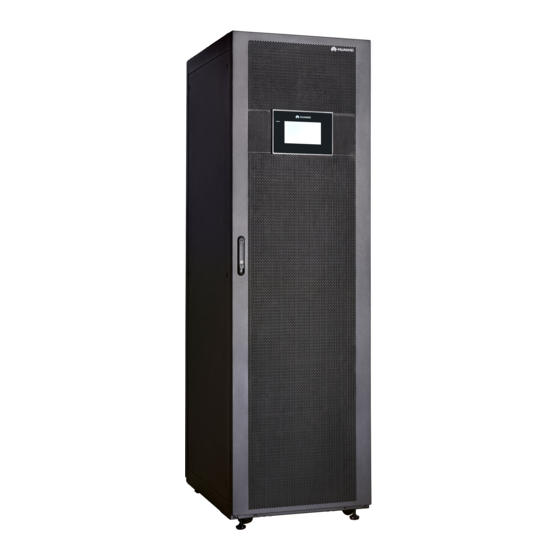
Page 25: Product Introduction
Manual startup is required to ensure that the inverter is in standby state and the power flow has reached the inverter. 2.3 Product Introduction 2.3.1 Structure Figure 2-8 shows the front view of the UPS cabinet. Issue 02 (2017-10-23) Huawei Proprietary and Confidential Copyright © Huawei Technologies Co., Ltd. -
Page 26: Power Module
(5) Bypass module (6) Power modules (7) Monitor display (8) Output switch module (MDU) (9) Maintenance bypass switch 2.3.2 Power Module Appearance Figure 2-9 shows a power module. Issue 02 (2017-10-23) Huawei Proprietary and Confidential Copyright © Huawei Technologies Co., Ltd. - Page 27 Dimensions (H x W x D): 86 mm x 442 mm x 620 mm Weight: < 21 kg Rated output capacity: 25 kVA/25 kW Power density: 17.2 W/inch Issue 02 (2017-10-23) Huawei Proprietary and Confidential Copyright © Huawei Technologies Co., Ltd.
-
Page 28: Bypass Module
The UPS is set to ECO mode and the bypass voltage is within the specified range. The power module is overloaded for a period longer than the maximum allowed period. Both the active and standby ECMs are abnormal. Issue 02 (2017-10-23) Huawei Proprietary and Confidential Copyright © Huawei Technologies Co., Ltd. -
Page 29: Optional) Surge Protective Module
In a standard configuration, the control module consists of two ECMs, one dry contact card, and one monitoring interface card (from left to right). The four cards are hot swappable. One Issue 02 (2017-10-23) Huawei Proprietary and Confidential Copyright © Huawei Technologies Co., Ltd. -
Page 30: Ecm
Ports are protected by a security mechanism. 2.3.5.2 ECM Appearance The control module consists of two energy control modules (ECMs) in active/standby mode. Figure 2-13 ECM Issue 02 (2017-10-23) Huawei Proprietary and Confidential Copyright © Huawei Technologies Co., Ltd. - Page 31 UPS5000 status information to other monitoring modules. The system provides three types of control area network (CAN) communication: monitoring CAN communication, intra-rack parallel CAN communication, and inter-rack parallel CAN communication. Issue 02 (2017-10-23) Huawei Proprietary and Confidential Copyright © Huawei Technologies Co., Ltd.
-
Page 32: Dry Contact Card
Disconnected: no Port for signal ground battery grounding fault Port for detecting diesel Connected: D.G. Disconnected generator (D.G.) mode mode Disconnected: Port for signal ground Issue 02 (2017-10-23) Huawei Proprietary and Confidential Copyright © Huawei Technologies Co., Ltd. - Page 33 STATUS_ SWITCH Port for monitoring the Connected: circuit Connected STATUS_ bypass input circuit breaker breaker ON Disconnected: circuit breaker SWITCH Port for signal ground STATUS_ Issue 02 (2017-10-23) Huawei Proprietary and Confidential Copyright © Huawei Technologies Co., Ltd.
-
Page 34: Monitoring Interface Card
MDU. The ports include the ambient temperature and humidity sensor port, iBAT 2.0 port, FE port, battery temperature monitoring port, and network management port. Issue 02 (2017-10-23) Huawei Proprietary and Confidential Copyright © Huawei Technologies Co., Ltd. - Page 35 DO_4 is used to output alarms and indicates battery mode by default. It can be set to indicate critical alarms, minor alarms, bypass mode, or low battery voltage. Issue 02 (2017-10-23) Huawei Proprietary and Confidential Copyright © Huawei Technologies Co., Ltd.
- Page 36 0.5–1.5 mm RS485 cables and FE cables must be shielded cables. Figure 2-17 Figure 2-18 are recommended wiring methods for DO ports. Figure 2-17 Wiring method 1 Issue 02 (2017-10-23) Huawei Proprietary and Confidential Copyright © Huawei Technologies Co., Ltd.
- Page 37 COM1 pin definitions. Figure 2-19 COM1 pins Table 2-6 COM1 pin definition Description RS485– RS485+ 12V_PORT Figure 2-20 Table 2-7 describe the COM2 pin definitions. Issue 02 (2017-10-23) Huawei Proprietary and Confidential Copyright © Huawei Technologies Co., Ltd.
- Page 38 Figure 2-20 COM2 pins Table 2-7 COM2 pin definition Description RS485+ RS485– RS485+ RS485– CANH0 CANL0 Figure 2-21 Table 2-8 describe the RS485 pin definitions. Figure 2-21 RS485 pins Issue 02 (2017-10-23) Huawei Proprietary and Confidential Copyright © Huawei Technologies Co., Ltd.
-
Page 39: Mdu
(2) LCD touchscreen Touch the LCD screen firmly because it is an industrial resistive touchscreen. It is recommended that you use your fingernails for accurate selection and quick response. Issue 02 (2017-10-23) Huawei Proprietary and Confidential Copyright © Huawei Technologies Co., Ltd. - Page 40 The indicator on the LCD panel is yellow when the bypass supplies power in non-ECO mode. The ports of the LCD screen are located at the side of the LCD screen. Figure 2-24 LCD screen ports Issue 02 (2017-10-23) Huawei Proprietary and Confidential Copyright © Huawei Technologies Co., Ltd.
-
Page 41: Typical Configurations
The dual-bus system is suitable for scenarios where high availability Dual-bus system requirements are posed for power supply. The dual-bus system supplies power to important loads in large- and medium-sized Issue 02 (2017-10-23) Huawei Proprietary and Confidential Copyright © Huawei Technologies Co., Ltd. -
Page 42: Single Ups
The parallel connections synchronize the UPS outputs to supply power to loads. If one UPS fails, the other UPSs continue supplying power to loads. Figure 2-25 shows a conceptual diagram of an N+X parallel system. Issue 02 (2017-10-23) Huawei Proprietary and Confidential Copyright © Huawei Technologies Co., Ltd. -
Page 43: Dual-Bus System
(STS) can be installed to start the bus synchronization controller (BSC). The UPS systems work in normal mode or bypass mode. Figure 2-26 shows a conceptual diagram of a dual-bus system. Issue 02 (2017-10-23) Huawei Proprietary and Confidential Copyright © Huawei Technologies Co., Ltd. -
Page 44: Optional Components
SPDs, which provide surge protection for mains input and bypass input respectively. The surge protective capacity reaches 5 kA if a surge protective module is configured. Issue 02 (2017-10-23) Huawei Proprietary and Confidential Copyright © Huawei Technologies Co., Ltd. - Page 45 The ECM extended subrack and the surge protective module do not support onsite installation. If you require this optional component, inform Huawei when you purchase the UPS. Huawei installs it before delivery. IP21 components cannot be configured when cables are routed from the top of the UPS.
-
Page 46: Installation
UPS5000-E-(25 kVA-125 kVA)-FM User Manual 3 Installation Installation 3.1 Installation Preparations 3.1.1 Site 3.1.1.1 UPS Dimensions Figure 3-1 UPS dimensions (unit: mm) Issue 02 (2017-10-23) Huawei Proprietary and Confidential Copyright © Huawei Technologies Co., Ltd. -
Page 47: Installation Environment
Install the UPS away from water sources, heat sources, and flammable or explosive materials. Keep the UPS away from direct sunlight, dust, volatile gases, corrosive materials, and air dense with salt particles. Issue 02 (2017-10-23) Huawei Proprietary and Confidential Copyright © Huawei Technologies Co., Ltd. -
Page 48: Installation Clearances
Figure 3-2 Reserved clearances (unit: mm) 3.1.2 Tools and Instruments Insulate installation tools to prevent electric shocks. Prepare the following tools and meters indicated in Table 3-1 for installation. Issue 02 (2017-10-23) Huawei Proprietary and Confidential Copyright © Huawei Technologies Co., Ltd. - Page 49 Polyvinyl chloride Cotton cloth Label Electrician's knife (PVC) insulation tape Electrostatic Protective gloves Insulated gloves Insulation protective discharge (ESD) shoes gloves Flat-head Torque screwdriver Cable cutter Brush screwdriver Issue 02 (2017-10-23) Huawei Proprietary and Confidential Copyright © Huawei Technologies Co., Ltd.
-
Page 50: Preparing Power Cables
100 kVA 125 kVA Mains input current inpu Recommen 4 x 10 4 x 25 4 x 50 4 x 70 4 x 95 cross-secti onal area Issue 02 (2017-10-23) Huawei Proprietary and Confidential Copyright © Huawei Technologies Co., Ltd. - Page 51 192 2 V battery cells, and 1.67 V/cell) (A) Recommen 3 x 16 3 x 50 3 x 70 3 x 120 3 x 150 cross-secti onal area – Issue 02 (2017-10-23) Huawei Proprietary and Confidential Copyright © Huawei Technologies Co., Ltd.
- Page 52 35 mm 46 N· m input terminals Output Crimped OT 11 mm 30 mm 26 N· m terminals Crimped OT 11 mm 30 mm 26 N· m Issue 02 (2017-10-23) Huawei Proprietary and Confidential Copyright © Huawei Technologies Co., Ltd.
- Page 53 R160 FFC 3P Bypass input circuit T1N160 TMD breaker R160 FFC 3P Downstream output T1N160 TMD circuit breaker R160 FFC 3P 100 kVA Mains input circuit T3N250 TMD Issue 02 (2017-10-23) Huawei Proprietary and Confidential Copyright © Huawei Technologies Co., Ltd.
-
Page 54: Unpacking And Checking
Step 2 Check the UPS packing. Step 3 Hold the sliding plate steady. Cut and remove the binding tapes. Put down the sliding plate gently. See Figure 3-3. Issue 02 (2017-10-23) Huawei Proprietary and Confidential Copyright © Huawei Technologies Co., Ltd. - Page 55 Step 5 Remove the plastic bag and take out the fittings box. Step 6 Check that the UPS is intact. Visually inspect the UPS appearance for shipping damage. If it is damaged, notify the carrier immediately. Issue 02 (2017-10-23) Huawei Proprietary and Confidential Copyright © Huawei Technologies Co., Ltd.
- Page 56 3 Installation Check that all fittings comply with the packing list. If some fittings are missing or do not comply with the packing list, record this information and contact your local Huawei office immediately. Step 7 After confirming that the UPS is intact, remove the front and rear L-shaped brackets that secure the UPS to the pallet, and secure the sliding plate to the pallet using the two M12 bolts removed before.
- Page 57 Ensure that the two screws are installed reliably. Otherwise, the sliding plate may shift when the UPS slides down. Step 8 Raise the four anchor bolts to the highest position using an adjustable wrench, as shown in Figure 3-7. Issue 02 (2017-10-23) Huawei Proprietary and Confidential Copyright © Huawei Technologies Co., Ltd.
-
Page 58: Installing A Single Ups
3.2 Installing a Single UPS 3.2.1 Installing the Cabinet Secured Installation Step 1 Determine the position for installing the cabinet. Mark mounting holes for the UPS based on the following figures: Issue 02 (2017-10-23) Huawei Proprietary and Confidential Copyright © Huawei Technologies Co., Ltd. - Page 59 Figure 3-10 shows how to install an expansion bolt. Figure 3-9 Expansion bolt composition (1) M12 bolt (2) Spring washer (3) Flat washer (4) Expansion sleeve Issue 02 (2017-10-23) Huawei Proprietary and Confidential Copyright © Huawei Technologies Co., Ltd.
- Page 60 Step 4 (Optional) If the castors of the UPS need to be lifted from the ground, perform steps Step 1 Step 2 Non-Secured Installation. Step 5 Remove the rear panel of the cabinet, as shown in Figure 3-11, and then open the front door. Issue 02 (2017-10-23) Huawei Proprietary and Confidential Copyright © Huawei Technologies Co., Ltd.
- Page 61 Step 6 Remove the four rubber plugs from the bottom of the cabinet (two at the front and two at the rear). Figure 3-12 Removing rubber plugs Step 7 Tighten the expansion bolts in the direction as shown in Figure 3-13. Issue 02 (2017-10-23) Huawei Proprietary and Confidential Copyright © Huawei Technologies Co., Ltd.
-
Page 62: Installing Batteries
Step 2 Check whether the bottom of the cabinet is horizontal by using a level. If the cabinet is not level, adjust the leveling feet. ----End 3.2.2 Installing Batteries Issue 02 (2017-10-23) Huawei Proprietary and Confidential Copyright © Huawei Technologies Co., Ltd. -
Page 63: Installing Optional Components
Figure 3-15 Antiseismic kit mounting hole positions (unit: mm) Step 2 Secure two antiseismic kits to the front and rear of the cabinet using twelve M5x16 screws and four M12 screws. Issue 02 (2017-10-23) Huawei Proprietary and Confidential Copyright © Huawei Technologies Co., Ltd. - Page 64 Step 5 Secure the two antiseismic kits at the front and rear of the cabinet to the floor using eight M12 expansion bolts, as shown in Figure 3-17. Figure 3-17 Securing the antiseismic kits to the floor ----End Issue 02 (2017-10-23) Huawei Proprietary and Confidential Copyright © Huawei Technologies Co., Ltd.
-
Page 65: Installing An Ip21 Component
Figure 3-18 Installing leveling feet Step 2 Secure the IP21 component to the top of each cabinet using four M12 screws. Figure 3-19 Installing the IP21 component ----End Issue 02 (2017-10-23) Huawei Proprietary and Confidential Copyright © Huawei Technologies Co., Ltd. -
Page 66: Connecting An Ambient T/H Sensor
Step 1 Connect the COM_OUT port on the CIM of the iBAT to the COM2 port on the monitoring interface card. For details, see iBAT 2.0-CIM01C2 Quick Guide. Figure 3-21 COM2 port ----End Issue 02 (2017-10-23) Huawei Proprietary and Confidential Copyright © Huawei Technologies Co., Ltd. -
Page 67: Routing Cables
Choose an appropriate cabling route based on the actual situation. The figure is for reference only. Step 4 Connect the cable with a crimped terminal to the corresponding copper bar. Step 5 Clean foreign matter inside the cabinet. Issue 02 (2017-10-23) Huawei Proprietary and Confidential Copyright © Huawei Technologies Co., Ltd. -
Page 68: Routing Cables From The Top
Remove the cable tray covers from the top of the cabinet for cable routing. Remove the small covers from the top of the cabinet, as shown in Figure 3-24. Issue 02 (2017-10-23) Huawei Proprietary and Confidential Copyright © Huawei Technologies Co., Ltd. - Page 69 Remove the large covers from the bottom of the cabinet, drill holes into them based on the number of cables and cable diameters, and install them at the position where the small covers were placed. Issue 02 (2017-10-23) Huawei Proprietary and Confidential Copyright © Huawei Technologies Co., Ltd.
- Page 70 If holes are drilled for routing cables, attach grommet strips on the hole edges to protect cables. Step 3 Connect the ground cable, as shown in Figure 3-26. Issue 02 (2017-10-23) Huawei Proprietary and Confidential Copyright © Huawei Technologies Co., Ltd.
- Page 71 Prepare the OT terminals onsite to ensure that the length of the copper wire is the same as that of the part of the OT terminal that covers the conductor. Figure 3-26 Connecting the ground cable Step 4 Connect the battery cable. Issue 02 (2017-10-23) Huawei Proprietary and Confidential Copyright © Huawei Technologies Co., Ltd.
- Page 72 Figure 3-28 Neutral wire Step 5 Connect input power cables. Dual mains Remove the copper bars between mains and bypass input terminals, as shown in Figure 3-29. Issue 02 (2017-10-23) Huawei Proprietary and Confidential Copyright © Huawei Technologies Co., Ltd.
- Page 73 3 Installation Figure 3-29 Removing copper bars Connect the mains input power cable. Figure 3-30 Connecting the mains input power cable Connect the bypass input power cable. Issue 02 (2017-10-23) Huawei Proprietary and Confidential Copyright © Huawei Technologies Co., Ltd.
- Page 74 Step 7 Route the signal cables for the left subrack along the left side of the cabinet and the signal cables for the right subrack along the right side of the cabinet, and then bind the cables to the cabinet. Issue 02 (2017-10-23) Huawei Proprietary and Confidential Copyright © Huawei Technologies Co., Ltd.
-
Page 75: Routing Cables From The Bottom
Route cables for the UPS from inside out and from bottom up. Step 1 Remove the filler panels from the front and bottom of the cabinet. Issue 02 (2017-10-23) Huawei Proprietary and Confidential Copyright © Huawei Technologies Co., Ltd. - Page 76 Install the large covers on the position where the small covers were placed at the top of the cabinet. Issue 02 (2017-10-23) Huawei Proprietary and Confidential Copyright © Huawei Technologies Co., Ltd.
- Page 77 The number of holes to be drilled is for reference only. If holes are drilled for routing cables, attach grommet strips on the hole edges to protect cables. Issue 02 (2017-10-23) Huawei Proprietary and Confidential Copyright © Huawei Technologies Co., Ltd.
- Page 78 Figure 3-36 Removing the large covers and drilling holes Step 3 Connect the ground cable. The ground cable is routed through the gap between inner and outer beams of the rack. Issue 02 (2017-10-23) Huawei Proprietary and Confidential Copyright © Huawei Technologies Co., Ltd.
- Page 79 For dual mains, remove the copper bar between mains and bypass input terminals, as shown Figure 3-29. Use routing cables by removing small covers as an example. Issue 02 (2017-10-23) Huawei Proprietary and Confidential Copyright © Huawei Technologies Co., Ltd.
- Page 80 UPS5000-E-(25 kVA-125 kVA)-FM User Manual 3 Installation Figure 3-38 Connecting the battery cable and output power cable (1) Output power cable (2) Battery cable (3) Cable tie Issue 02 (2017-10-23) Huawei Proprietary and Confidential Copyright © Huawei Technologies Co., Ltd.
- Page 81 Step 5 Connect and route the signal cables for the left subrack along the left side of the cabinet and the signal cables for the right subrack along the right side of the cabinet, and then bind the cables to the cabinet. Issue 02 (2017-10-23) Huawei Proprietary and Confidential Copyright © Huawei Technologies Co., Ltd.
- Page 82 Route cables for the UPS from inside out and from bottom up. Step 1 (Optional) Determine the installation position for the cable entry cabinet, and mark mounting holes at the installation position based on drawings. Issue 02 (2017-10-23) Huawei Proprietary and Confidential Copyright © Huawei Technologies Co., Ltd.
- Page 83 Step 3 Adjust the anchor bolts of the cable entry cabinet to make it flush with the UPS. Step 4 Install the front and rear connecting kits. Issue 02 (2017-10-23) Huawei Proprietary and Confidential Copyright © Huawei Technologies Co., Ltd.
- Page 84 Remove small covers for routing cables Remove a certain number of small covers in the front row from the bottom of the cable entry cabinet based on the actual cable conditions. Issue 02 (2017-10-23) Huawei Proprietary and Confidential Copyright © Huawei Technologies Co., Ltd.
- Page 85 Remove the large cover from the bottom of the cable entry cabinet, drill holes into it based on site requirements, and install it at the position where the small covers were placed. Issue 02 (2017-10-23) Huawei Proprietary and Confidential Copyright © Huawei Technologies Co., Ltd.
- Page 86 3 Installation Figure 3-44 Removing the large cover for routing cables Step 7 Route the ground cable and power cables from the bottom of the cable entry cabinet. Issue 02 (2017-10-23) Huawei Proprietary and Confidential Copyright © Huawei Technologies Co., Ltd.
- Page 87 Issue 02 (2017-10-23) Huawei Proprietary and Confidential Copyright © Huawei Technologies Co., Ltd.
-
Page 88: Remote Epo
----End 3.2.5 Remote EPO Huawei does not provide the EPO switch or cable. If the cable is required, the recommended cable is 22 AWG. Equip the EPO switch with a protective cover to prevent misoperations, and cover the cable with protective tubing. -
Page 89: Connecting Communications Cables
Step 1 Connect the external network management device to the RS485 port. Step 2 Connect the network port on a PC to the FE port. ----End 3.3 Installing a Parallel System 3.3.1 Installing the UPSs Context Issue 02 (2017-10-23) Huawei Proprietary and Confidential Copyright © Huawei Technologies Co., Ltd. - Page 90 Figure 3-49. Figure 3-49 Connecting parallel plates You also need to connect parallel plates at the rear of the UPS. ----End Issue 02 (2017-10-23) Huawei Proprietary and Confidential Copyright © Huawei Technologies Co., Ltd.
-
Page 91: Connecting Power Cables
1+1 parallel system, Figure 3-51 shows the cable connections for this system. Figure 3-50 Conceptual diagram of a 1+1 parallel system Issue 02 (2017-10-23) Huawei Proprietary and Confidential Copyright © Huawei Technologies Co., Ltd. - Page 92 UPS systems, and Figure 3-53 shows the cable connections for this system. Figure 3-52 Conceptual diagram of a dual-bus system Issue 02 (2017-10-23) Huawei Proprietary and Confidential Copyright © Huawei Technologies Co., Ltd.
-
Page 93: Connecting Signal Cables
----End 3.3.3 Connecting Signal Cables Context This topic describes how to connect signal cables as a loop for four UPSs in a parallel system. Issue 02 (2017-10-23) Huawei Proprietary and Confidential Copyright © Huawei Technologies Co., Ltd. - Page 94 In a dual-bus system, you need to connect cables to BSC ports on the UPSs. Figure 3-56 shows the cable connections for a dual-bus system containing two master systems. Issue 02 (2017-10-23) Huawei Proprietary and Confidential Copyright © Huawei Technologies Co., Ltd.
-
Page 95: Installation Verification
UPS may be damaged. Table 3-6 Installation checklist Item Acceptance Criteria UPS installation The UPS is securely installed and does not tilt due to vibration. Issue 02 (2017-10-23) Huawei Proprietary and Confidential Copyright © Huawei Technologies Co., Ltd. - Page 96 4. Ensure that there is no foreign matter on the bottom plate of the cabinet. 5. Ensure that there is no foreign matter on the rear module subrack. Issue 02 (2017-10-23) Huawei Proprietary and Confidential Copyright © Huawei Technologies Co., Ltd.
- Page 97 3. Do not remove the dustproof cover before power-on to prevent dust inside the UPS, as shown in Figure 3-59. Figure 3-57 Positions to be checked for foreign matter Issue 02 (2017-10-23) Huawei Proprietary and Confidential Copyright © Huawei Technologies Co., Ltd.
- Page 98 UPS5000-E-(25 kVA-125 kVA)-FM User Manual 3 Installation Figure 3-58 Fill the holes with flake sealing putty (1) Flake sealing putty Figure 3-59 Dustproof cover (1) Dustproof cover Issue 02 (2017-10-23) Huawei Proprietary and Confidential Copyright © Huawei Technologies Co., Ltd.
-
Page 99: User Interface
4 User Interface User Interface 4.1 LCD Interface 4.1.1 LCD Menu 4.1.1.1 Menu Hierarchy Figure 4-1 shows the LCD menu hierarchy. Figure 4-1 Menu hierarchy 4.1.1.2 Initial Startup Issue 02 (2017-10-23) Huawei Proprietary and Confidential Copyright © Huawei Technologies Co., Ltd. -
Page 100: Main Menu
The LCD screen is divided into three parts: status bar, alarm bar and information area. Figure numerically labels functions of the default main screen, and Table 4-1 describes these functions. Issue 02 (2017-10-23) Huawei Proprietary and Confidential Copyright © Huawei Technologies Co., Ltd. - Page 101 Table 4-2 Functions of common buttons Button Function Returns to the main screen. Scrolls the page down. Scrolls the page up. Returns to the upper-level menu. Logs a user out. Issue 02 (2017-10-23) Huawei Proprietary and Confidential Copyright © Huawei Technologies Co., Ltd.
-
Page 102: System Info Screen
Runn Info screen. On this screen, AC Output, UPS Load, Mains Input, and Bypass Input can be queried, as shown in Figure 4-6 Figure 4-7. Issue 02 (2017-10-23) Huawei Proprietary and Confidential Copyright © Huawei Technologies Co., Ltd. - Page 103 On the System Info > Settings > CIM Param. > Basic Param. screen, if the Number of battery strings is not 0, the Battery Detailed Data is displayed on the Runn Info screen. Issue 02 (2017-10-23) Huawei Proprietary and Confidential Copyright © Huawei Technologies Co., Ltd.
- Page 104 AC output phase current AC output frequency Frequency (Hz) Power factor Proportion of output active power to output apparent power. UPS Load Figure 4-9 UPS Load screen Issue 02 (2017-10-23) Huawei Proprietary and Confidential Copyright © Huawei Technologies Co., Ltd.
- Page 105 Phase current (A) Mains input phase current Frequency (Hz) Mains input frequency Proportion of the mains input active power Power factor to the mains input apparent power. Issue 02 (2017-10-23) Huawei Proprietary and Confidential Copyright © Huawei Technologies Co., Ltd.
- Page 106 Frequency (Hz) Bypass input frequency Proportion of the mains input active power Power factor to the mains input apparent power. Battery Status Figure 4-12 Battery Status screen Issue 02 (2017-10-23) Huawei Proprietary and Confidential Copyright © Huawei Technologies Co., Ltd.
- Page 107 Status Item Description Time for which the UPS runs in bypass Bypass runtime (h) mode. Inv. runtime (h) Time for which the UPS runs in inverter mode. Issue 02 (2017-10-23) Huawei Proprietary and Confidential Copyright © Huawei Technologies Co., Ltd.
- Page 108 Ambient humid. (%) temperature and humidity sensor. If the sensor is not installed, NA is displayed. Mod. Cur. Eql. Data Figure 4-15 shows the Mod. Cur. Eql. Data screen. Issue 02 (2017-10-23) Huawei Proprietary and Confidential Copyright © Huawei Technologies Co., Ltd.
- Page 109 This screen details battery string data and single battery data in each battery string. The N in String N Battery Data should be less than or equal to 4. Figure 4-17 shows the Batt. String Data screen. Issue 02 (2017-10-23) Huawei Proprietary and Confidential Copyright © Huawei Technologies Co., Ltd.
-
Page 110: Alarms Screen
CIM and BIM. 4.1.2.3 Alarms Screen on the System Info screen to enter the Alarms screen. Issue 02 (2017-10-23) Huawei Proprietary and Confidential Copyright © Huawei Technologies Co., Ltd. - Page 111 UPS5000-E-(25 kVA-125 kVA)-FM User Manual 4 User Interface Figure 4-19 Alarms screen Active Alarms Figure 4-20 Active Alarms screen Issue 02 (2017-10-23) Huawei Proprietary and Confidential Copyright © Huawei Technologies Co., Ltd.
- Page 112 If this selection is enabled, the buzzer is muted. If the buzzer is enabled, Buzzer Off is displayed on the operation screen. Figure 4-22 Buzzer Off screen Issue 02 (2017-10-23) Huawei Proprietary and Confidential Copyright © Huawei Technologies Co., Ltd.
-
Page 113: Settings Screen
If a user is not currently logged in, a login screen is displayed. If an incorrect password is entered three consecutive times, the account will be locked out for 5 minutes. Issue 02 (2017-10-23) Huawei Proprietary and Confidential Copyright © Huawei Technologies Co., Ltd. - Page 114 Ensure the date and time is set correctly. Incorrect time display in running and alarm information can cause analysis errors during maintenance or repair. Set basic parameters, as shown in Figure 4-27 Figure 4-28. Issue 02 (2017-10-23) Huawei Proprietary and Confidential Copyright © Huawei Technologies Co., Ltd.
- Page 115 Communications Settings Set communications parameters, as shown in Figure 4-29, Figure 4-30 Figure 4-31. Issue 02 (2017-10-23) Huawei Proprietary and Confidential Copyright © Huawei Technologies Co., Ltd.
- Page 116 UPS5000-E-(25 kVA-125 kVA)-FM User Manual 4 User Interface Figure 4-29 Communication screen 1 Figure 4-30 Communication screen 2 Figure 4-31 Communication screen 3 Issue 02 (2017-10-23) Huawei Proprietary and Confidential Copyright © Huawei Technologies Co., Ltd.
- Page 117 Subnet mask Set an Ethernet subnet mask that ranges from 0.0.0.0 to 255.255.255.255. The default value is 255.255.255.0. Gateway Issue 02 (2017-10-23) Huawei Proprietary and Confidential Copyright © Huawei Technologies Co., Ltd.
- Page 118 The default status is Disable. If a short-distance battery temperature sensor is configured, set NTC to Enable. Basic Parameter Settings Issue 02 (2017-10-23) Huawei Proprietary and Confidential Copyright © Huawei Technologies Co., Ltd.
- Page 119 2 V or 12 V. The number of cells must be a multiple of 12 (for example, 180 and 192). Cell float voltage, Cell equalized volt, Float volt. temp. comp. coef., and EOD voltage threshold are set for cells. Issue 02 (2017-10-23) Huawei Proprietary and Confidential Copyright © Huawei Technologies Co., Ltd.
- Page 120 Advanced parameters, such as the system capacity and power module capacity, can be set as shown in Figure 4-33 Figure 4-36. Figure 4-33 Advanced Param. screen 1 Figure 4-34 Advanced Param. screen 2 Issue 02 (2017-10-23) Huawei Proprietary and Confidential Copyright © Huawei Technologies Co., Ltd.
- Page 121 The value can be Normal mode (default), Converter mode, Self-load mode, or ECO. BSC mode − The value can be Non-BSC mode (default) or BSC mode (set when the system is a dual-bus system). Issue 02 (2017-10-23) Huawei Proprietary and Confidential Copyright © Huawei Technologies Co., Ltd.
- Page 122 (less than 420 V) within Bus overvolt. recovery time. The default value is 5s. Capacitor failure detection Issue 02 (2017-10-23) Huawei Proprietary and Confidential Copyright © Huawei Technologies Co., Ltd.
- Page 123 Set this parameter to the rack dustproof maintenance period. When it is set to 0, there is no reminder. Input Parameter Settings Set input parameters, as shown in Figure 4-37. Figure 4-37 Input Param. screen Issue 02 (2017-10-23) Huawei Proprietary and Confidential Copyright © Huawei Technologies Co., Ltd.
- Page 124 Weak input adaptability is suitable for mains and AC input sources. The default value is Strong. Output Param. screen Set output parameters, as shown in Figure 4-38. Figure 4-38 Output Param. screen Issue 02 (2017-10-23) Huawei Proprietary and Confidential Copyright © Huawei Technologies Co., Ltd.
- Page 125 Bypass Parameter Settings Set bypass parameters, such as the bypass voltage and frequency range, as shown in Figure 4-39. Figure 4-39 Bypass Param. screen Bypass frequency range (Hz) Issue 02 (2017-10-23) Huawei Proprietary and Confidential Copyright © Huawei Technologies Co., Ltd.
- Page 126 This parameter specifies whether to start bypass mode if overtemperature occurs. Battery Parameter Settings Battery parameter settings impact the battery maintenance, battery lifespan, and UPS discharge time. When you set battery parameters, note the following: Issue 02 (2017-10-23) Huawei Proprietary and Confidential Copyright © Huawei Technologies Co., Ltd.
- Page 127 BMU. If the BMU is not configured, you do not need to set these two parameters. Set battery parameters, as shown in Figure 4-40 Figure 4-44. Figure 4-40 Battery Param. screen 1 Issue 02 (2017-10-23) Huawei Proprietary and Confidential Copyright © Huawei Technologies Co., Ltd.
- Page 128 UPS5000-E-(25 kVA-125 kVA)-FM User Manual 4 User Interface Figure 4-41 Battery Param. screen 2 Figure 4-42 Battery Param. screen 3 Figure 4-43 Battery Param. screen 4 Issue 02 (2017-10-23) Huawei Proprietary and Confidential Copyright © Huawei Technologies Co., Ltd.
- Page 129 Enable forced equalized charging when batteries are continuously under float charging or hibernation. When the forced equalized charging time reaches the value of this parameter, float charging starts. Issue 02 (2017-10-23) Huawei Proprietary and Confidential Copyright © Huawei Technologies Co., Ltd.
- Page 130 The value 0 indicates no hibernation. − The Class 2 grid hiber. Time value range is 0–15 days, and the default value is 6 days. The value 0 indicates no hibernation. Issue 02 (2017-10-23) Huawei Proprietary and Confidential Copyright © Huawei Technologies Co., Ltd.
- Page 131 Dry contact extended card (MUE07A): provides two routes of input signals and one route of output signals. Set the dry contact parameters, as shown in Figure 4-45 Figure 4-51. Issue 02 (2017-10-23) Huawei Proprietary and Confidential Copyright © Huawei Technologies Co., Ltd.
- Page 132 UPS5000-E-(25 kVA-125 kVA)-FM User Manual 4 User Interface Figure 4-45 Dry Contacts screen 1 Figure 4-46 Dry Contacts screen 2 Figure 4-47 Dry Contacts screen 3 Issue 02 (2017-10-23) Huawei Proprietary and Confidential Copyright © Huawei Technologies Co., Ltd.
- Page 133 UPS5000-E-(25 kVA-125 kVA)-FM User Manual 4 User Interface Figure 4-48 Dry Contacts screen 4 Figure 4-49 Dry Contacts screen 5 Figure 4-50 Dry Contacts screen 6 Issue 02 (2017-10-23) Huawei Proprietary and Confidential Copyright © Huawei Technologies Co., Ltd.
- Page 134 Set this parameter to determine whether the port is used to detect the status of the PDU input surge protector, or system output switch. MUE06A connection Issue 02 (2017-10-23) Huawei Proprietary and Confidential Copyright © Huawei Technologies Co., Ltd.
- Page 135 Corresponds to signal of the input dry contact DI_1 on the MUE07A. MUE07A DI_2 Corresponds to signal of the input dry contact DI_2 on the MUE07A. MUE07A DI_3 Issue 02 (2017-10-23) Huawei Proprietary and Confidential Copyright © Huawei Technologies Co., Ltd.
- Page 136 0, the Battery Detailed Data is displayed on the Runn Info screen. Figure 4-53 Figure 4-54 show the Basic Param. screen. Figure 4-53 Basic Parameters 1 Issue 02 (2017-10-23) Huawei Proprietary and Confidential Copyright © Huawei Technologies Co., Ltd.
- Page 137 Number of batteries in a battery string. A battery string contains a maximum of 300 batteries. − CIM logical start addr Communication start address when the northbound device queries CIM data. Figure 4-55 shows the Advanced Param. screen. Issue 02 (2017-10-23) Huawei Proprietary and Confidential Copyright © Huawei Technologies Co., Ltd.
- Page 138 On this screen, the CIM No. and BIM No. can be set under each battery string. Figure 4-56 Batt. String Config 1 Issue 02 (2017-10-23) Huawei Proprietary and Confidential Copyright © Huawei Technologies Co., Ltd.
-
Page 139: Maintenance Screen
USB Operations, Inv. ON, and Inv. OFF. If a user is not currently logged in, a dialog box will display for entering a user name and password. Figure 4-58 Maintenance screen 1 Issue 02 (2017-10-23) Huawei Proprietary and Confidential Copyright © Huawei Technologies Co., Ltd. - Page 140 Test, and Capacity Test. The next maintenance time displayed on the screen indicates the upcoming time in which to check batteries. Figure 4-60 shows the Battery Maint. screen. Issue 02 (2017-10-23) Huawei Proprietary and Confidential Copyright © Huawei Technologies Co., Ltd.
- Page 141 Export Config., Export Logs, Export Alarms, and other functions for upgrading software, and downloading system data, as shown in Figure 4-61 Figure 4-62. Figure 4-61 USB Operations screen 1 Issue 02 (2017-10-23) Huawei Proprietary and Confidential Copyright © Huawei Technologies Co., Ltd.
- Page 142 Use the LCD to start and shut down the inverter. Before the inverter starts, the system asks for confirmation to prevent misoperations. Figure 4-63 shows the Inv. ON screen, and Figure 4-64 shows the Inv. OFF screen. Figure 4-63 Inv. ON screen Issue 02 (2017-10-23) Huawei Proprietary and Confidential Copyright © Huawei Technologies Co., Ltd.
- Page 143 (a dialog box will display asking for confirmation to prevent misoperations). After switchover, ensure that the ECM has stopped working (the yellow or red indicator is on, or the green indicator is blinking) before maintaining it. Issue 02 (2017-10-23) Huawei Proprietary and Confidential Copyright © Huawei Technologies Co., Ltd.
- Page 144 Figure 4-66. Figure 4-66 Screen Calib. screen CIM Control Reset the specified CIM and BIM, and sets the BIM blinking function or measures the BIM internal resistance. Issue 02 (2017-10-23) Huawei Proprietary and Confidential Copyright © Huawei Technologies Co., Ltd.
- Page 145 Bus Capa. Life If the service life of a capacitor is about to end, that is, Module X bus capacitor life (y) is less than 1.0, contact Huawei technical support to replace the power module. Issue 02 (2017-10-23) Huawei Proprietary and Confidential...
-
Page 146: About Screen
On the main screen, tap System Status. On the System Status to view the mains input, bypass input, load, and battery information, as shown in Figure 4-70. Issue 02 (2017-10-23) Huawei Proprietary and Confidential Copyright © Huawei Technologies Co., Ltd. -
Page 147: Common Functions Screen
Figure 4-71 Figure 4-72. Figure 4-71 Common Functions screen 1 Issue 02 (2017-10-23) Huawei Proprietary and Confidential Copyright © Huawei Technologies Co., Ltd. -
Page 148: Webui
Step 2 On the Advanced tab page, ensure that Use TLS 1.0, Use TLS 1.1, and Use TLS 1.2 are selected and click OK, as shown in Figure 4-73. Issue 02 (2017-10-23) Huawei Proprietary and Confidential Copyright © Huawei Technologies Co., Ltd. - Page 149 WebUI, including system running information Changeme browsing, system information (historical alarms, logs, e-labels, and fault data) exporting, parameter (system parameters and battery parameters) setting, system control Issue 02 (2017-10-23) Huawei Proprietary and Confidential Copyright © Huawei Technologies Co., Ltd.
-
Page 150: Monitoring Page
It is advised to change the password after the first login using User Mgmt. on the Config. page to prevent unauthorized access. ----End 4.2.2 Monitoring Page After a user logs in to the WebUI, the Monitoring page is displayed by default. Issue 02 (2017-10-23) Huawei Proprietary and Confidential Copyright © Huawei Technologies Co., Ltd. -
Page 151: Active Alarms Page
The Active Alarms page is displayed by default. Information Displays system monitoring information. area 4.2.2.1 Active Alarms Page The Active Alarms page details active alarms, as shown in Figure 4-75. Issue 02 (2017-10-23) Huawei Proprietary and Confidential Copyright © Huawei Technologies Co., Ltd. -
Page 152: Real-Time Data Page
Param. Settings page, as shown in Figure 4-77. The setting method is the same as that on the LCD. For details, see 4.1.2.4 Settings Screen. Issue 02 (2017-10-23) Huawei Proprietary and Confidential Copyright © Huawei Technologies Co., Ltd. -
Page 153: Comm. Config. Page
Figure 4-78 Comm. Config. page 4.2.2.5 CIM Parameters Open the CIM Param. page to set basic parameters, advanced parameters, and battery string configurations, as shown in Figure 4-79. Issue 02 (2017-10-23) Huawei Proprietary and Confidential Copyright © Huawei Technologies Co., Ltd. -
Page 154: Control Page
On the homepage, click the Query tab to open the Historical Alarms page for querying historical alarms based on severity, generation time, and clear time, as shown in Figure 4-81. Issue 02 (2017-10-23) Huawei Proprietary and Confidential Copyright © Huawei Technologies Co., Ltd. -
Page 155: Logs Page
Historical logs can be exported but not queried. Figure 4-82 Logs Page 4.2.4 Config. Page 4.2.4.1 User Management On the home page, choose Config. > User Mgmt. Issue 02 (2017-10-23) Huawei Proprietary and Confidential Copyright © Huawei Technologies Co., Ltd. -
Page 156: Site Config. Page
If the password complexity check is enabled, the user password is required to be a string of 6–20 characters and contain at least two types of characters. 4.2.4.2 Site Config. Page On the home page, choose Config. > Site Config. Issue 02 (2017-10-23) Huawei Proprietary and Confidential Copyright © Huawei Technologies Co., Ltd. - Page 157 Customers can replace the UPS certificate with the certificate trusted by them. ModbusTCP CA Certificate Management: Import a CA certificate to verify the validity of the Modbus TCP access certificate. Issue 02 (2017-10-23) Huawei Proprietary and Confidential Copyright © Huawei Technologies Co., Ltd.
-
Page 158: Rccmd
SSL Encrypted Transmission and Event Configuration will be displayed on the page, as shown in Figure 4-86. Figure 4-85 RCCMD function disabled Figure 4-86 RCCMD function enabled Issue 02 (2017-10-23) Huawei Proprietary and Confidential Copyright © Huawei Technologies Co., Ltd. - Page 159 The MDU supports 17 alarm events, and a maximum of 50 jobs can be added for each event, as shown in Figure 4-89. Figure 4-89 shows the buttons on the Event Configuration page, Table 4-6 describes these buttons. Issue 02 (2017-10-23) Huawei Proprietary and Confidential Copyright © Huawei Technologies Co., Ltd.
- Page 160 You can delete all jobs of the event by clicking this button. Figure 4-90 shows the buttons after one event is expanded and Table 4-7 describes these buttons. Issue 02 (2017-10-23) Huawei Proprietary and Confidential Copyright © Huawei Technologies Co., Ltd.
- Page 161 When adding a job, the job types to be selected are: RCCMD Shutdown, RCCMD Message, RCCMD Execute, and RCCMD TRAP. RCCMD Shutdown is selected by default. For different job types, you need to enter different contents. Issue 02 (2017-10-23) Huawei Proprietary and Confidential Copyright © Huawei Technologies Co., Ltd.
- Page 162 RCCMD Message: Specify the RCCMD client IP address, port, and message to be conveyed. The RCCMD client will receive the message. For example, enter "This is a test message". Figure 4-92 RCCMD message Issue 02 (2017-10-23) Huawei Proprietary and Confidential Copyright © Huawei Technologies Co., Ltd.
- Page 163 UPS input voltage value (for example, single-phase: 220 V; three-phase A: 220 V, B: 220 V, C: 220 V). Table 4-8 lists the signal names that can be entered. Issue 02 (2017-10-23) Huawei Proprietary and Confidential Copyright © Huawei Technologies Co., Ltd.
- Page 164 #STATUS UPS status #RUNTIME UPS operating time minutes #BATTVOLT Battery voltage #INFREQ Input frequency #BYPASSINFREQ Bypass input frequency #OUTFREQ Output frequency #CNT_PF Power supply failure times Issue 02 (2017-10-23) Huawei Proprietary and Confidential Copyright © Huawei Technologies Co., Ltd.
- Page 165 After the certificate is uploaded successfully, click Submit. The WebUI of the MDU will restart, and the uploaded certificate will be used for communication. Issue 02 (2017-10-23) Huawei Proprietary and Confidential Copyright © Huawei Technologies Co., Ltd.
-
Page 166: Managing The Ups By Using The Nms Complying With Rfc1628 Standard
MIB file which allows the third-party NMS to manage the UPS remotely. Figure 4-96 Download the MIB The UPS-RFC1628-MIB has more alarms than RFC1628. Download the UPS-RFC1628-MIB before using. Issue 02 (2017-10-23) Huawei Proprietary and Confidential Copyright © Huawei Technologies Co., Ltd. -
Page 167: Maint. Page
On the homepage, click the Maint. tab to access the Calib., Commissioning Var., Upgrade, and Download tabs for performing maintenance operations on the bypass, module, and ECM, as shown in Figure 4-98 Figure 4-102. Figure 4-98 Calib. page Issue 02 (2017-10-23) Huawei Proprietary and Confidential Copyright © Huawei Technologies Co., Ltd. - Page 168 UPS5000-E-(25 kVA-125 kVA)-FM User Manual 4 User Interface Figure 4-99 Commissioning Var. page Figure 4-100 Upgrade page Figure 4-101 Download page Issue 02 (2017-10-23) Huawei Proprietary and Confidential Copyright © Huawei Technologies Co., Ltd.
-
Page 169: Protecting The Server By Using The Rccmd Software
Step 1 On the RCCMD client, choose Connections, add the server IP address, and set the encryption mode to encryption. If encryption is disabled, you do not need to select the encrypted transmission. All configurations take effect only after restart. Issue 02 (2017-10-23) Huawei Proprietary and Confidential Copyright © Huawei Technologies Co., Ltd. - Page 170 Send the message to the RCCMD client, indicating that the inverter is on. Step 6 On the RCCMD client, you can view messages through the View Event Log at the upper left corner. ----End Issue 02 (2017-10-23) Huawei Proprietary and Confidential Copyright © Huawei Technologies Co., Ltd.
-
Page 171: Ups Alive Check Function
CS121/UPSMAN Traps. If by polling CS121/UPSMAN every x seconds... is selected as the method of detecting heartbeats, set the detection method. The default interval is 1800s and detection is performed 100 times, as shown in Figure 4-104. Issue 02 (2017-10-23) Huawei Proprietary and Confidential Copyright © Huawei Technologies Co., Ltd. - Page 172 UPS5000-E-(25 kVA-125 kVA)-FM User Manual 4 User Interface Figure 4-104 Heartbeat detecting mode on the RCCMD client You can also manually detect heartbeat by clicking Run alive check now..Issue 02 (2017-10-23) Huawei Proprietary and Confidential Copyright © Huawei Technologies Co., Ltd.
- Page 173 UPS5000-E-(25 kVA-125 kVA)-FM User Manual 4 User Interface Figure 4-105 Detecting heartbeat manually Figure 4-106 Detecting heartbeat manually and successfully ----End Issue 02 (2017-10-23) Huawei Proprietary and Confidential Copyright © Huawei Technologies Co., Ltd.
-
Page 174: Operations
Before powering on the UPS, check that all external and internal switches are OFF (except for the ready switches for the power module and bypass module, which are in locked state). Figure 5-1 Bypass module ready switch Issue 02 (2017-10-23) Huawei Proprietary and Confidential Copyright © Huawei Technologies Co., Ltd. - Page 175 (Optional) If a surge protective module is configured, turn on its switch. Turn on the internal bypass input switch, mains input switch, and output switch. The UPS starts initialization. The LCD displays the Huawei logo and an initialization progress bar.
- Page 176 Figure 5-4 Time screen On the Network Param. screen, set IP address allocation, IP address, Subnet mask, and Gateway, as shown in Figure 5-5. Issue 02 (2017-10-23) Huawei Proprietary and Confidential Copyright © Huawei Technologies Co., Ltd.
- Page 177 5-6. Set the Output voltage level, Output frequency, Battery capacity, and Number of cells, as shown in Figure 5-7. System parameter settings affect UPS operation. Before setting system parameters, note the following: Issue 02 (2017-10-23) Huawei Proprietary and Confidential Copyright © Huawei Technologies Co., Ltd.
- Page 178 Set Output frequency correctly; otherwise, loads may not work properly. Figure 5-6 System Param. 1 screen Battery parameter settings impact the battery maintenance, battery lifespan, and UPS discharge time. Before setting battery parameters, note the following: Issue 02 (2017-10-23) Huawei Proprietary and Confidential Copyright © Huawei Technologies Co., Ltd.
- Page 179 High or low charging power may shorten the battery lifespan, or even damage batteries. If the battery capacity cannot be confirmed, contact Huawei technical support. Number of cells refers to the number of 2 V cells in a single battery string connected to the UPS.
- Page 180 On the Advanced tab page, ensure that Use TLS 1.0, Use TLS 1.1, and Use TLS 1.2 are selected and click OK, as shown in Figure 5-10. Issue 02 (2017-10-23) Huawei Proprietary and Confidential Copyright © Huawei Technologies Co., Ltd.
- Page 181 Enter https://UPS IP address in the address box of the browser. Select a language. Enter a user name and password, and click Login to open the homepage, as shown in Figure 5-11. Issue 02 (2017-10-23) Huawei Proprietary and Confidential Copyright © Huawei Technologies Co., Ltd.
- Page 182 AC Output data on the LCD, as shown in Figure 5-13 Figure 5-14. Use a multimeter to measure the three-phase output voltage and frequency. Issue 02 (2017-10-23) Huawei Proprietary and Confidential Copyright © Huawei Technologies Co., Ltd.
- Page 183 Moreover, the UPS may shut down before the discharging is completed, which may result in data backup failure. Table 5-1 lists examples of setting battery parameters. Issue 02 (2017-10-23) Huawei Proprietary and Confidential Copyright © Huawei Technologies Co., Ltd.
- Page 184 Step 9 (Optional) If the BCB box is configured, choose Settings > Dry Contacts, set MUE05A connection to Enable, and then set BCB connection [OL] and Battery breaker [STA] to Enable. Figure 5-15 BCB connection Issue 02 (2017-10-23) Huawei Proprietary and Confidential Copyright © Huawei Technologies Co., Ltd.
-
Page 185: Shutting Down And Powering Off The Ups
If an incorrect password is entered three consecutive times, the account will be locked out for 5 minutes. In the displayed dialog box, tap Yes to shut down the inverter, as shown in Figure 5-16. Issue 02 (2017-10-23) Huawei Proprietary and Confidential Copyright © Huawei Technologies Co., Ltd. - Page 186 Step 2 After the inverter shuts down, if the bypass is normal, the UPS transfers to bypass mode; if the bypass is not normal, the UPS supplies no power, and the loads shut down, as shown in Figure 5-18 Figure 5-19. Issue 02 (2017-10-23) Huawei Proprietary and Confidential Copyright © Huawei Technologies Co., Ltd.
- Page 187 If the inverter needs to shut down to transfer the UPS to bypass mode, check that the UPS has not generated an alarm and perform Step If you need to shut down the UPS, perform all of the preceding steps. ----End Issue 02 (2017-10-23) Huawei Proprietary and Confidential Copyright © Huawei Technologies Co., Ltd.
-
Page 188: Starting The Ups In Battery Mode
Step 4 Press and hold down the BATT start button on the bypass module for at least 2 seconds. Figure 5-20 shows the position of the battery cold start button. The system automatically enters the battery cold start status. The LCD displays the Huawei logo and an initialization progress bar. Figure 5-20 Battery startup button Step 5 After LCD initialization is complete, start the inverter. -
Page 189: Setting Eco Mode
Step 2 Select a value (± 5%, ± 6%, ± 7%, ± 8%, ± 9%, or ± 10%) from the ECO voltage range drop-down list box, as shown in Figure 5-21. Issue 02 (2017-10-23) Huawei Proprietary and Confidential Copyright © Huawei Technologies Co., Ltd. - Page 190 Step 3 Set Working mode to ECO. The information indicating that the UPS works in ECO mode is displayed on the LCD, as shown in Figure 5-22. Figure 5-22 Setting ECO mode Step 4 Manually start the inverter. Issue 02 (2017-10-23) Huawei Proprietary and Confidential Copyright © Huawei Technologies Co., Ltd.
-
Page 191: Testing Batteries
If the inverter is not started, the UPS may be disconnected. Figure 5-23 System Status screen ----End 5.6 Testing Batteries 5.6.1 Forced Equalized Charging Test Context Before a forced equalized charging test, ensure that: Issue 02 (2017-10-23) Huawei Proprietary and Confidential Copyright © Huawei Technologies Co., Ltd. - Page 192 The forced equalized charging test automatically stops in any of the following cases: The forced equalized charging test duration reaches the forced equalized charging protection time (12–24 h, 18 h by default). Issue 02 (2017-10-23) Huawei Proprietary and Confidential Copyright © Huawei Technologies Co., Ltd.
-
Page 193: Shallow Discharge Test
Step 2 On the Maintenance screen, tap Battery Maint, as shown in Figure 5-24. Step 3 Tap Start next to Shallow Dis. Test to start a shallow discharge test. Issue 02 (2017-10-23) Huawei Proprietary and Confidential Copyright © Huawei Technologies Co., Ltd. -
Page 194: Capacity Test
The mains, batteries, charger, and discharger are normal. No overload alarm is generated. Procedure Step 1 On the main screen of the LCD, tap System Info. Tap . The Maintenance screen is displayed. Issue 02 (2017-10-23) Huawei Proprietary and Confidential Copyright © Huawei Technologies Co., Ltd. -
Page 195: Test Data Download
Step 2 On the main screen of the LCD, choose System Info. Tap . The Maintenance screen is displayed. Step 3 Choose USB Operations > Export Logs, and select a log download path. Issue 02 (2017-10-23) Huawei Proprietary and Confidential Copyright © Huawei Technologies Co., Ltd. -
Page 196: Download Over The Webui
Step 1 Log in to the WebUI. Step 2 Choose Query > Logs, select logs from the Log drop-down list box, then click Export to export logs. Issue 02 (2017-10-23) Huawei Proprietary and Confidential Copyright © Huawei Technologies Co., Ltd. -
Page 197: Transferring To Maintenance Bypass Mode
The maintenance bypass switch in the figures below is for reference only. Close the maintenance bypass switch according to site specifications. The Maint. breaker closed alarm is displayed in the alarm list, as shown in Figure 5-33. Issue 02 (2017-10-23) Huawei Proprietary and Confidential Copyright © Huawei Technologies Co., Ltd. - Page 198 UPS5000-E-(25 kVA-125 kVA)-FM User Manual 5 Operations Figure 5-31 Removing the baffle plate before the maintenance bypass switch Figure 5-32 Closing the maintenance bypass switch Issue 02 (2017-10-23) Huawei Proprietary and Confidential Copyright © Huawei Technologies Co., Ltd.
-
Page 199: Transferring From Maintenance Bypass Mode To Normal Mode
The Maint. breaker closed alarm disappears from the alarm list. Check whether the UPS works in bypass mode by viewing the system running status diagram on the LCD or WebUI. Issue 02 (2017-10-23) Huawei Proprietary and Confidential Copyright © Huawei Technologies Co., Ltd. -
Page 200: Performing Epo
Figure 5-34 Opening the maintenance bypass switch Figure 5-35 Reinstalling the baffle plate for the maintenance bypass switch Step 2 Start the inverter. ----End 5.9 Performing EPO Issue 02 (2017-10-23) Huawei Proprietary and Confidential Copyright © Huawei Technologies Co., Ltd. - Page 201 Press the EPO button connected to the dry contact card or remove the 4-pin terminal from the EPO port on the dry contact card. Figure 5-36 EPO ports Figure 5-37 EPO alarm displayed on the LCD Issue 02 (2017-10-23) Huawei Proprietary and Confidential Copyright © Huawei Technologies Co., Ltd.
-
Page 202: Clearing The Epo State
On the LCD, choose System Info > Alarms and tap Clear Faults. If you have not logged in, a login screen is displayed. Enter a user name and password, and tap Issue 02 (2017-10-23) Huawei Proprietary and Confidential Copyright © Huawei Technologies Co., Ltd. - Page 203 Login to open the homepage. Choose Monitoring > Control > System Commands and Tests and click Clear Fault. The EPO alarm is cleared successfully. Issue 02 (2017-10-23) Huawei Proprietary and Confidential Copyright © Huawei Technologies Co., Ltd.
- Page 204 Login to open the homepage. Choose Monitoring > Active Alarms to check that the EPO alarm is cleared. If the bypass input is normal, the UPS transfers to bypass mode. Issue 02 (2017-10-23) Huawei Proprietary and Confidential Copyright © Huawei Technologies Co., Ltd.
-
Page 205: Exporting Data
E-Label Serviceable data This topic describes how to export historical alarms. Procedure Step 1 Choose Query > Historical Alarms, and set Severity, Generated, and Cleared. Issue 02 (2017-10-23) Huawei Proprietary and Confidential Copyright © Huawei Technologies Co., Ltd. -
Page 206: Setting Hibernation Mode
This improves the system efficiency, reduces power consumption, and increases the power module service life. Use the LCD or WebUI to set hibernation mode. Before enabling the hibernation mode: Issue 02 (2017-10-23) Huawei Proprietary and Confidential Copyright © Huawei Technologies Co., Ltd. -
Page 207: Lcd
Figure 5-46 Hibernation parameters on the LCD Step 3 On the LCD, choose Enable from the Paral. sys. hibernate drop-down list box. A confirmation message is displayed, as shown in Figure 5-47. Issue 02 (2017-10-23) Huawei Proprietary and Confidential Copyright © Huawei Technologies Co., Ltd. -
Page 208: Webui
Figure 5-48 Hibernation parameters on the WebUI Step 3 On the WebUI, select Enable from the drop-down list box and click Submit. Click Submit after you set the parameter on the WebUI. Issue 02 (2017-10-23) Huawei Proprietary and Confidential Copyright © Huawei Technologies Co., Ltd. - Page 209 UPS5000-E-(25 kVA-125 kVA)-FM User Manual 5 Operations Step 4 Set Module cycle hiber. period (d) to an integer ranging from 1 to 100. The default value is ----End Issue 02 (2017-10-23) Huawei Proprietary and Confidential Copyright © Huawei Technologies Co., Ltd.
-
Page 210: Routine Maintenance
Power grid Input voltage: 380 V AC, 400 If the input voltage is environment V AC, or 415 V AC (line abnormal, check the power grid Issue 02 (2017-10-23) Huawei Proprietary and Confidential Copyright © Huawei Technologies Co., Ltd. -
Page 211: Quarterly Maintenance
The insulation layer of Replace the cables. (between the UPS and the cables is intact and terminals Secure the output are free from black marks Issue 02 (2017-10-23) Huawei Proprietary and Confidential Copyright © Huawei Technologies Co., Ltd. -
Page 212: Battery Maintenance
Before installing batteries, read through the battery user manuals and pay attention to safety precautions and connection methods provided by battery manufacture. When installing and maintaining batteries, pay attention to the following points: Issue 02 (2017-10-23) Huawei Proprietary and Confidential Copyright © Huawei Technologies Co., Ltd. -
Page 213: Precautions For Battery Maintenance
(2.35 V/cell ± 1%) x number of and the battery input terminals battery cells at the UPS side is greater than Issue 02 (2017-10-23) Huawei Proprietary and Confidential Copyright © Huawei Technologies Co., Ltd. -
Page 214: Quarterly Maintenance
3. If the fault persists, contact Issue 02 (2017-10-23) Huawei Proprietary and Confidential Copyright © Huawei Technologies Co., Ltd. -
Page 215: Annual Maintenance
(A torque wrench is used for checking the torque. After checking that the battery screws meet the requirements, mark the screws for later check.) Issue 02 (2017-10-23) Huawei Proprietary and Confidential Copyright © Huawei Technologies Co., Ltd. -
Page 216: Troubleshooting
Close the battery switch and charge batteries until each battery has a voltage greater than the EOD voltage and 11.3 V/cell. For details about how to rectify common faults, see Table 7-1. If any unmentioned faults occur, see the alarm list chapter, or contact Huawei technical support. Table 7-1 Troubleshooting Case Symptom Possible Cause... - Page 217 The bypass thyristor is Replace the bypass bypass and the Fault indicator is damaged. module. is not The bypass module Reduce the load, or normal. experiences improve ventilation. overtemperature. Issue 02 (2017-10-23) Huawei Proprietary and Confidential Copyright © Huawei Technologies Co., Ltd.
- Page 218 UPS5000-E-(25 kVA-125 kVA)-FM User Manual 7 Troubleshooting For details about component replacement and maintenance involved in Troubleshooting and Alarm List, consult Huawei maintenance engineers. Issue 02 (2017-10-23) Huawei Proprietary and Confidential Copyright © Huawei Technologies Co., Ltd.
-
Page 219: Technical Specifications
8.2 Internal Switch Parameters Switch UPS5000-E-125K-FM Maintenan 690 V AC/250 A/3P ce bypass switch Mains 690 V AC/250 A/3P input switch Bypass 690 V AC/250 A/3P input switch Issue 02 (2017-10-23) Huawei Proprietary and Confidential Copyright © Huawei Technologies Co., Ltd. -
Page 220: Environmental Specifications
For details, see the IEC62040-3. 8.4 Safety Regulations and EMC Item UPS5000-E-125K-FM Safety regulations EN62040-1: 2013 IEC62040-1: 2013 YD/T2165-2010 CQC3108-2011/GB7260.1-2008 EN62040-2 IEC62040-2 IEC61000-2-2 IEC61000-4-2 IEC61000-4-3 IEC61000-4-4 IEC61000-4-5 IEC61000-4-6 IEC61000-4-8 IEC61000-4-11 Issue 02 (2017-10-23) Huawei Proprietary and Confidential Copyright © Huawei Technologies Co., Ltd. -
Page 221: Mains Input Electrical Specifications
The UPS supports 30 to 44 batteries and is configured with 32 batteries by default. The positive and negative battery strings respectively contain 16 batteries. If 30 batteries are configured, the power is derated to 94%. Issue 02 (2017-10-23) Huawei Proprietary and Confidential Copyright © Huawei Technologies Co., Ltd. -
Page 222: Output Electrical Specifications
Bypass overload capability: Ambient temperature = 30° C, load = 135%, run for a long time Ambient temperature = 40° C, load = 125%, run for Issue 02 (2017-10-23) Huawei Proprietary and Confidential Copyright © Huawei Technologies Co., Ltd. -
Page 223: System Electrical Specifications
200%,run for 1 minute Load > 1000%, run for 100 ms 8.9 System Electrical Specifications Item UPS5000-E-125K-FM System efficiency Up to 96% ECO in a parallel system Supported Issue 02 (2017-10-23) Huawei Proprietary and Confidential Copyright © Huawei Technologies Co., Ltd. -
Page 224: A Menu Hierarchy
Total Runtime Environment Data Alarms Active Alarms Historical Alarms Buzzer Off Clear Faults Settings Basic Communication Basic Param. Advanced Param. Input Param. Output Param. Bypass Param. Battery Param. Issue 02 (2017-10-23) Huawei Proprietary and Confidential Copyright © Huawei Technologies Co., Ltd. - Page 225 Monitoring Version Power Version Version Info Common AC Output Phase voltage Functions Line voltage Phase current Frequency Power factor UPS Load Active power Apparent power Reactive power Issue 02 (2017-10-23) Huawei Proprietary and Confidential Copyright © Huawei Technologies Co., Ltd.
-
Page 226: Menus On The Webui
Level 4 Menu Level 5 Menu Menu Menu Monitorin Active Alarms Real-time Input Phase voltage Data Line voltage Current Power factor Frequency Bypass Phase voltage Line voltage Current Issue 02 (2017-10-23) Huawei Proprietary and Confidential Copyright © Huawei Technologies Co., Ltd. - Page 227 Battery Voltage Current Bus voltage Battery temperature Backup time Remaining capacity Environment Data Ambient temperature Ambient humidity Module Rectifier Phase voltage Line voltage Current Power factor Issue 02 (2017-10-23) Huawei Proprietary and Confidential Copyright © Huawei Technologies Co., Ltd.
- Page 228 Param. Basic Single/Parallel Settings Parameters Voltage level Output frequency Battery capacity Number of cells Advanced System capacity Parameters Power module capacity Requisite modules Redundant modules Working mode Issue 02 (2017-10-23) Huawei Proprietary and Confidential Copyright © Huawei Technologies Co., Ltd.
- Page 229 Capacitor failure detection lower limit Input cur. limiting Input cur. limiting ratio No load output shows zero Current equal. detection Bus Capa. Life Altitude ModbusTCP encryption Issue 02 (2017-10-23) Huawei Proprietary and Confidential Copyright © Huawei Technologies Co., Ltd.
- Page 230 Minimum bypass voltage ECO voltage range BPM mode upon BPM overtemp Battery Installation time Parameters Maintenance period Battery type Chg. cur. limiting coef. Cell float voltage Issue 02 (2017-10-23) Huawei Proprietary and Confidential Copyright © Huawei Technologies Co., Ltd.
- Page 231 Sched. shallow dis. test interval Shallow dis. test dis. ratio Undertemp. alarm thresh. Overtemp. alarm thresh. Backup time warning Backup time warn. thresh. Remain. cap. warning Issue 02 (2017-10-23) Huawei Proprietary and Confidential Copyright © Huawei Technologies Co., Ltd.
- Page 232 Battery ground fault D.G. connection BCB connection Battery breaker PDC output breaker PDC maintenance breaker BP/SYSMT Switch BP/SYSMT switch function SPD/SYSOUT Switch SPD/SYSOUT switch function MUE06A connection Issue 02 (2017-10-23) Huawei Proprietary and Confidential Copyright © Huawei Technologies Co., Ltd.
- Page 233 MUE07A DO_2 MUE07A DO_3 MUE07A DO_4 MUE07A DO_5 MUE07A DI_1 MUE07A DI_2 MUE07A DI_3 MUE07A DI_4 MUE07A DI_5 Comm. System IP IP Address Config. Settings Subnet Mask Issue 02 (2017-10-23) Huawei Proprietary and Confidential Copyright © Huawei Technologies Co., Ltd.
- Page 234 Clear Fault Bypass runtime (Clear) Inv. runtime (Clear) Forced equalized charging (Start, Stop) Shallow discharge test (Start, Stop) Capacity Test (Start, Stop) CIM Control CIM No. BIM No. Issue 02 (2017-10-23) Huawei Proprietary and Confidential Copyright © Huawei Technologies Co., Ltd.
- Page 235 Time zone System Date Date(Local) and Time Time(Local) System Name Information Location Contact information SNMP SNMP version SNMP port SNMP Trap Trap addr. Trap port SNMP version User Issue 02 (2017-10-23) Huawei Proprietary and Confidential Copyright © Huawei Technologies Co., Ltd.
- Page 236 Alarm Severity Scheduled Notifi. ModbusTCP Upload Certificate Password Management Confirm password ModbusTCP Upload CA Certificate Management ModbusTCP Authentication Authentication New password Confirm password eUPS Upload Certificate Password Issue 02 (2017-10-23) Huawei Proprietary and Confidential Copyright © Huawei Technologies Co., Ltd.
- Page 237 Neg. batt. dis. cur. Inv. ph. A volt. Inv. ph. B volt. Inv. ph. C volt. Ph. A output volt. Ph. B output volt. Ph. C output volt. Issue 02 (2017-10-23) Huawei Proprietary and Confidential Copyright © Huawei Technologies Co., Ltd.
- Page 238 Commissioni BPM SW Bypass ng Var. commissioning var. 0 data BPM SW commissioning var. 1 data BPM SW commissioning var. 2 data BPM SW commissioning var. Issue 02 (2017-10-23) Huawei Proprietary and Confidential Copyright © Huawei Technologies Co., Ltd.
- Page 239 Inv. SW commissioning var. 1 data Inv. SW commissioning var. 2 data Inv. SW commissioning var. 3 data Inv. SW commissioning var. 4 data Inv. SW commissioning var. Issue 02 (2017-10-23) Huawei Proprietary and Confidential Copyright © Huawei Technologies Co., Ltd.
- Page 240 4 data ECM SW commissioning var. 5 data Upgrade Upgrade UPS Software Download Download Serviceable data E-Label Bus Capa. Bus Capa. Life Module Life Bus capacitor life Issue 02 (2017-10-23) Huawei Proprietary and Confidential Copyright © Huawei Technologies Co., Ltd.
-
Page 241: B (Optional) Tn-C System Application
If the TN-C system is adopted, short-circuit the input N and PE. The recommended cross-sectional area for the cable is 50 mm The following cable connections are for reference only. Figure B-1 Connecting the input N and PE Issue 02 (2017-10-23) Huawei Proprietary and Confidential Copyright © Huawei Technologies Co., Ltd. -
Page 242: C Alarm List
0001-3 The mains is Check the mains. not normal. 0004-1 Mains ph. Minor Cable Verify the cable connections. Reversed connections are incorrect. Issue 02 (2017-10-23) Huawei Proprietary and Confidential Copyright © Huawei Technologies Co., Ltd. - Page 243 Bypass The phase Check whether the cable phase 0011-1 Minor phase sequence of sequence is correct using a reversed multimeter. If no multimeter is Issue 02 (2017-10-23) Huawei Proprietary and Confidential Copyright © Huawei Technologies Co., Ltd.
- Page 244 Minor parameters are correctly set. overvoltage configure d number 2. If they are correctly set, certain batteries may be faulty. batteries 3. Check whether the battery Issue 02 (2017-10-23) Huawei Proprietary and Confidential Copyright © Huawei Technologies Co., Ltd.
- Page 245 Replace the board. 1. Check the battery voltage. 0032-1 Battery Critical overvoltage battery 2. Check that the configured Issue 02 (2017-10-23) Huawei Proprietary and Confidential Copyright © Huawei Technologies Co., Ltd.
- Page 246 2. Check whether the fans are functioning properly. Replace functionin the power module if the fans are faulty. properly. The air channel Issue 02 (2017-10-23) Huawei Proprietary and Confidential Copyright © Huawei Technologies Co., Ltd.
- Page 247 1. Rectify the fault and check 0061-2 Inverter Minor The I2C whether the alarm is cleared. alarm bus is not 2. If the alarm is generated again, Issue 02 (2017-10-23) Huawei Proprietary and Confidential Copyright © Huawei Technologies Co., Ltd.
- Page 248 1. Check that there is no overload. Output The load 0566-1 Minor overload 2. Check that the module power is excessive. not derated due to a fan fault. Issue 02 (2017-10-23) Huawei Proprietary and Confidential Copyright © Huawei Technologies Co., Ltd.
- Page 249 3. Replace the ECM. disconnec ted or short-circ uited. Only one rack works in a parallel system. An ECM is faulty. Replace the inter-rack parallel 0583-4 inter-rack Issue 02 (2017-10-23) Huawei Proprietary and Confidential Copyright © Huawei Technologies Co., Ltd.
- Page 250 0087-1 System Warning Check the reason why the transfer-to- neighboring neighboring UPS transfers to Issue 02 (2017-10-23) Huawei Proprietary and Confidential Copyright © Huawei Technologies Co., Ltd.
- Page 251 The running status is displayed. See disabled disabled. details about how to handle other alarms. 0334 Warning BSC master The running status is displayed. No master system. further measures are required. Issue 02 (2017-10-23) Huawei Proprietary and Confidential Copyright © Huawei Technologies Co., Ltd.
- Page 252 1. Reduce the load. Insufficient The load 0594-1 Minor redundant 2. Decrease the configured number racks excessive. of redundant racks. configure d number Issue 02 (2017-10-23) Huawei Proprietary and Confidential Copyright © Huawei Technologies Co., Ltd.
- Page 253 ON. shared and input circuit 2. Check that bypass input and breakers output power cables on each are OFF. rack meet the length requirements. Issue 02 (2017-10-23) Huawei Proprietary and Confidential Copyright © Huawei Technologies Co., Ltd.
- Page 254 2. After maintenance, open the maintenance circuit breaker and then start the inverter. 0380 Warning The inverter Wait until the inverter self-check is self-check is in complete. self-check. Issue 02 (2017-10-23) Huawei Proprietary and Confidential Copyright © Huawei Technologies Co., Ltd.
-
Page 255: D Acronyms And Abbreviations
BCB-BOX BBB-BOX battery bus bar box control area network Conformite Europeenne digital signal processing economic control operation emergency power off energy control module end of discharge Issue 02 (2017-10-23) Huawei Proprietary and Confidential Copyright © Huawei Technologies Co., Ltd. - Page 256 RS485 Recommend Standard 485 SNMP Simple Network Management Protocol state of charge state of health static transfer switch total distortion of the input current waveform THDi Issue 02 (2017-10-23) Huawei Proprietary and Confidential Copyright © Huawei Technologies Co., Ltd.
- Page 257 UPS5000-E-(25 kVA-125 kVA)-FM User Manual D Acronyms and Abbreviations total harmonic distortion of output voltage THDv uninterruptible power system Universal Serial Bus valve-regulated lead acid battery VRLA Issue 02 (2017-10-23) Huawei Proprietary and Confidential Copyright © Huawei Technologies Co., Ltd.
Need help?
Do you have a question about the UPS5000-E-****-FM series and is the answer not in the manual?
Questions and answers