Huawei UPS5000-E User Manual
Hide thumbs
Also See for UPS5000-E:
- User manual (300 pages) ,
- Quick manual (20 pages) ,
- User manual (201 pages)

Related Manuals for Huawei UPS5000-E


Summary of Contents for Huawei UPS5000-E
- Page 1 UPS5000-E-(400 kVA-800 kVA) User Manual (50 kVA Power Modules) Issue Date 2023-07-10 HUAWEI DIGITAL POWER TECHNOLOGIES CO., LTD.
- Page 2 Notice The purchased products, services and features are stipulated by the contract made between Huawei Digital Power Technologies Co., Ltd. and the customer. All or part of the products, services and features described in this document may not be within the purchase scope or the usage scope. Unless otherwise specified in the contract, all statements, information, and recommendations in this document are provided "AS IS"...
-
Page 3: About This Document
About This Document About This Document Purpose This document describes the UPS5000-E in terms of its features, performance specifications, working principles, appearance as well as instructions for installation, and operation and maintenance (O&M). UPS is short for uninterruptible power system. - Page 4 2017-04-28 Updated some MDU screenshots. 2017-02-25 Updated the voltage and current data of the monitoring interface card. 2016-10-14 This issue is the first official release. Issue 17 (2023-07-10) Copyright © Huawei Digital Power Technologies Co., Ltd.
-
Page 5: Table Of Contents
2.3.5 Control Module.................................. 45 2.3.5.1 Overview................................... 45 2.3.5.2 ECM..................................... 45 2.3.5.3 Dry contact card................................48 2.3.5.4 Monitoring Interface Card............................50 2.3.6 MDU....................................... 55 2.4 Typical Configurations................................. 58 2.4.1 Single UPS.................................... 59 Issue 17 (2023-07-10) Copyright © Huawei Digital Power Technologies Co., Ltd. - Page 6 3.2.7 Routing Cables (800 kVA UPS)..........................127 3.2.7.1 Top Cable Routing............................... 128 3.2.7.2 Bottom Cable Routing............................... 135 3.2.8 Connecting a Remote EPO Switch..........................143 3.2.9 Connecting Communications Cables........................144 3.3 Installing a Parallel System............................. 144 Issue 17 (2023-07-10) Copyright © Huawei Digital Power Technologies Co., Ltd.
- Page 7 8.4 Transferring to Bypass Mode............................201 8.5 Performing EPO...................................202 8.6 Clearing the EPO State..............................202 8.7 Exporting Data..................................203 8.8 Obtaining Active Alarm Details............................. 204 8.9 Spare Parts Authorization..............................204 Issue 17 (2023-07-10) Copyright © Huawei Digital Power Technologies Co., Ltd.
- Page 8 9.7 Battery Specifications................................ 208 9.8 Output Electrical Specifications............................. 209 9.9 System Electrical Specifications............................. 210 A (Optional) TN-C System Application................211 B User Interface........................213 C Alarm List..........................214 D Acronyms and Abbreviations................... 215 Issue 17 (2023-07-10) Copyright © Huawei Digital Power Technologies Co., Ltd.
-
Page 9: Safety Information
Equipment damage due to force majeure such as earthquakes, floods, volcanic eruptions, debris flows, lightning strikes, fires, wars, armed conflicts, typhoons, hurricanes, tornadoes, and extreme weather conditions ● Operation beyond the conditions specified in this document Issue 17 (2023-07-10) Copyright © Huawei Digital Power Technologies Co., Ltd. -
Page 10: Personal Safety
D ANGER During operations, use dedicated insulated tools to prevent electric shocks or short circuits. The insulation and voltage resistance must comply with local laws, regulations, standards, and specifications. Issue 17 (2023-07-10) Copyright © Huawei Digital Power Technologies Co., Ltd. - Page 11 – Trained personnel: personnel who are trained in technology and safety, have required experience, are aware of possible hazards on themselves in Issue 17 (2023-07-10) Copyright © Huawei Digital Power Technologies Co., Ltd.
-
Page 12: Equipment Safety
Issue 17 (2023-07-10) Copyright © Huawei Digital Power Technologies Co., Ltd. -
Page 13: Battery Safety
Do not expose batteries at high temperatures or around heat sources, such as scorching sunlight, fire sources, transformers, and heaters. Battery overheating may cause leakage, smoke, flammable gas release, thermal runaway, fire, or explosion. Issue 17 (2023-07-10) Copyright © Huawei Digital Power Technologies Co., Ltd. - Page 14 D ANGER The gas generated by a burning battery may irritate your eyes, skin, and throat. Take protective measures promptly. Issue 17 (2023-07-10) Copyright © Huawei Digital Power Technologies Co., Ltd.
- Page 15 WARNING After batteries are discharged, charge them in time to avoid damage due to overdischarge. Issue 17 (2023-07-10) Copyright © Huawei Digital Power Technologies Co., Ltd.
- Page 16 ● Batteries are damaged because you do not store them in accordance with storage requirements (for example, in an environment that is damp or prone to rain). Issue 17 (2023-07-10) Copyright © Huawei Digital Power Technologies Co., Ltd.
- Page 17 In the case of electrolyte leakage or structural deformation, contact the installer or professional O&M personnel immediately to remove or replace the battery. Issue 17 (2023-07-10) Copyright © Huawei Digital Power Technologies Co., Ltd.
- Page 18 ● Skin contact: Wash the affected areas immediately with soap and water and seek immediate medical attention. ● Intake: Seek immediate medical attention. Issue 17 (2023-07-10) Copyright © Huawei Digital Power Technologies Co., Ltd.
-
Page 19: Electrical Safety
Before connecting cables, ensure that the equipment is intact. Otherwise, electric shocks or fires may occur. D ANGER Non-standard and improper operations may result in fire or electric shocks. Issue 17 (2023-07-10) Copyright © Huawei Digital Power Technologies Co., Ltd. - Page 20 ● Before installing power cables, check that cable labels are correct and cable terminals are insulated. Issue 17 (2023-07-10) Copyright © Huawei Digital Power Technologies Co., Ltd.
- Page 21 Ensure that the ground resistance of the system for lightning protection is less than or equal to 10 ohms. ● Do not operate the equipment in the absence of a properly installed ground conductor. Issue 17 (2023-07-10) Copyright © Huawei Digital Power Technologies Co., Ltd.
- Page 22 Do not perform any improper operations, for example, dropping cables directly from a vehicle. Otherwise, the cable performance may deteriorate due to cable damage, which affects the current-carrying capacity and temperature rise. Issue 17 (2023-07-10) Copyright © Huawei Digital Power Technologies Co., Ltd.
-
Page 23: Environmental Requirements
Do not expose the equipment to flammable or explosive gas or smoke. Do not perform any operation on the equipment in such environments. D ANGER Do not store any flammable or explosive materials in the equipment area. Issue 17 (2023-07-10) Copyright © Huawei Digital Power Technologies Co., Ltd. - Page 24 ● Ensure that the ground in the installation environment is solid, free from spongy or soft soil, and not prone to subsidence. The site must not be located Issue 17 (2023-07-10) Copyright © Huawei Digital Power Technologies Co., Ltd.
-
Page 25: Mechanical Safety
Do not use tools that have signs of scratches or fail to pass the inspection or whose inspection validity period has expired. Ensure that the tools are secure and not overloaded. Issue 17 (2023-07-10) Copyright © Huawei Digital Power Technologies Co., Ltd. - Page 26 If two persons or more move a heavy object together, ensure that the object is lifted and landed simultaneously and moved at a uniform pace under the supervision of one person. Issue 17 (2023-07-10) Copyright © Huawei Digital Power Technologies Co., Ltd.
- Page 27 Only trained and qualified personnel are allowed to work at heights. ● Do not work at heights when steel pipes are wet or other risky situations exist. After the preceding conditions no longer exist, the safety owner and Issue 17 (2023-07-10) Copyright © Huawei Digital Power Technologies Co., Ltd.
- Page 28 Ensure that the ladder is securely positioned and held firm. ● When climbing up the ladder, keep your body stable and your center of gravity between the side rails, and do not overreach to the sides. Issue 17 (2023-07-10) Copyright © Huawei Digital Power Technologies Co., Ltd.
- Page 29 During hoisting, do not stand or walk under the crane or the hoisted objects. ● Do not drag steel ropes and hoisting tools or bump hoisted objects against hard objects during hoisting. Issue 17 (2023-07-10) Copyright © Huawei Digital Power Technologies Co., Ltd.
- Page 30 To avoid short circuits or other risks, do not drill holes into buried pipes or cables. ● When drilling holes, protect the equipment from shavings. After drilling, clean up any shavings. Issue 17 (2023-07-10) Copyright © Huawei Digital Power Technologies Co., Ltd.
-
Page 31: Product Overview
UPS5000-E-800K-SM ● UPS5000-E-800K-FM Figure 2-1 UPS model number Table 2-1 Model number details Item Description Product UPS, short for uninterruptible category power system UPS family 5000 E series subcategory Issue 17 (2023-07-10) Copyright © Huawei Digital Power Technologies Co., Ltd. -
Page 32: Working Principle
● FM: full configuration NO TE ● The UPS5000-E-400K-SM/FM uses 50 kVA power modules. It can expand up to 400 kVA and is compatible downwards to 50 kVA. This document describes the 400 kVA UPS. ● The UPS5000-E-500K-SM/FM uses 50 kVA power modules. It can expand up to 500 kVA and is compatible downwards to 50 kVA. -
Page 33: Working Modes
In normal mode, the rectifier converts AC power into DC power, and then the inverter converts the DC power into high-precision AC outputs. The conversions protect loads from interference such as input harmonics, glitches, and voltage transients. Issue 17 (2023-07-10) Copyright © Huawei Digital Power Technologies Co., Ltd. -
Page 34: Bypass Mode
In bypass mode, loads are powered by the bypass module. The bypass power supply is not protected by the UPS and therefore is prone to the mains outage, abnormal AC voltage waveform, or abnormal frequency. Issue 17 (2023-07-10) Copyright © Huawei Digital Power Technologies Co., Ltd. -
Page 35: Battery Mode
If the utility power input is abnormal or the rectifier becomes abnormal, the UPS transfers to battery mode. The power module obtains DC power from batteries, and the power is converted into AC output by the inverter. Issue 17 (2023-07-10) Copyright © Huawei Digital Power Technologies Co., Ltd. -
Page 36: Maintenance Bypass Mode
2.2.2.4 Maintenance Bypass Mode When the UPS works in maintenance bypass mode, the current flows through the maintenance bypass instead of the power module. You can maintain the circuit inside the cabinet. Issue 17 (2023-07-10) Copyright © Huawei Digital Power Technologies Co., Ltd. -
Page 37: Eco Mode
UPS transfers from bypass mode to inverter mode. In bypass mode or normal mode, the rectifier keeps working and charges batteries using a charger. The ECO mode delivers a high efficiency. Issue 17 (2023-07-10) Copyright © Huawei Digital Power Technologies Co., Ltd. -
Page 38: Product Introduction
Figure 2-7 UPS conceptual diagram in ECO mode NO TE Manual startup is required to ensure that the inverter is in standby state and the power flow has reached the inverter. 2.3 Product Introduction Issue 17 (2023-07-10) Copyright © Huawei Digital Power Technologies Co., Ltd. -
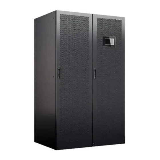
Page 39: Appearance
User Manual (50 kVA Power Modules) 2 Product Overview 2.3.1 Appearance Figure 2-8 400 kVA/500 kVA UPS (1) Power cabinet (2) Anchor baffle (3) Monitor display (4) Bypass cabinet plates unit (MDU) Issue 17 (2023-07-10) Copyright © Huawei Digital Power Technologies Co., Ltd. - Page 40 UPS5000-E-(400 kVA-800 kVA) User Manual (50 kVA Power Modules) 2 Product Overview Figure 2-9 600 kVA UPS (1) Power cabinet (2) Anchor baffle (3) MDU (4) Bypass cabinet plates Issue 17 (2023-07-10) Copyright © Huawei Digital Power Technologies Co., Ltd.
- Page 41 2 Product Overview Figure 2-10 800 kVA UPS (1) Power cabinet 1 (2) Power cabinet 2 (3) Anchor baffle plates (4) MDU (5) Bypass cabinet 2 (6) Bypass cabinet 1 Issue 17 (2023-07-10) Copyright © Huawei Digital Power Technologies Co., Ltd.
-
Page 42: Product Structure
2.3.2 Product Structure Figure 2-11 Product structure (400 kVA in standard configuration) (1) Power modules (2) Control module (3) Power distribution module cover (4) Maintenance bypass switch (5) Bypass module Issue 17 (2023-07-10) Copyright © Huawei Digital Power Technologies Co., Ltd. - Page 43 (1) Power modules (2) Control module (3) Power distribution module cover (4) Maintenance bypass switch (5) Bypass module (6) Mains input switch (7) Output switch (8) Bypass input switch Issue 17 (2023-07-10) Copyright © Huawei Digital Power Technologies Co., Ltd.
- Page 44 2 Product Overview Figure 2-13 Product structure (500 kVA in standard configuration) (1) Power modules (2) Control module (3) Power distribution module cover (4) Maintenance bypass switch (5) Bypass module Issue 17 (2023-07-10) Copyright © Huawei Digital Power Technologies Co., Ltd.
- Page 45 (1) Power modules (2) Control module (3) Power distribution module cover (4) Maintenance bypass switch (5) Bypass module (6) Mains input switch (7) Output switch (8) Bypass input switch Issue 17 (2023-07-10) Copyright © Huawei Digital Power Technologies Co., Ltd.
- Page 46 2 Product Overview Figure 2-15 Product structure (600 kVA in standard configuration) (1) Power modules (2) Control module (3) Power distribution module cover (4) Maintenance bypass switch (5) Bypass module Issue 17 (2023-07-10) Copyright © Huawei Digital Power Technologies Co., Ltd.
- Page 47 (1) Power modules (2) Control module (3) Power distribution module cover (4) Maintenance bypass switch (5) Bypass module (6) Mains input switch (7) Output switch (8) Bypass input switch Issue 17 (2023-07-10) Copyright © Huawei Digital Power Technologies Co., Ltd.
- Page 48 (1) Power modules (2) Control module (3) Maintenance bypass switch (4) Power distribution module (5) Bypass module (6) Mains input switch cover (7) Output switch (8) Bypass input switch Issue 17 (2023-07-10) Copyright © Huawei Digital Power Technologies Co., Ltd.
-
Page 49: Power Module
The module is not configured, the inverter fast software and rectifier software are being upgraded, or the inverter software is being upgraded (blinking at 4 Hz, on for 0.125s and off for 0.125s). Issue 17 (2023-07-10) Copyright © Huawei Digital Power Technologies Co., Ltd. - Page 50 Dimensions (H x W x D): 130 mm x 442 mm x 620 mm ● Weight: ≤ 35 kg ● Rated output capacity: 50 kVA/50 kW ● Power density: 50 kVA/3 U Issue 17 (2023-07-10) Copyright © Huawei Digital Power Technologies Co., Ltd.
-
Page 51: Bypass Module
Figure 2-21 800 kVA bypass module (1) Positioning lock (2) Cold start button (3) Running indicator (4) Alarm indicator (5) Fault indicator (6) Ready switch (7) Crowbar (8) Auxiliary power supply Issue 17 (2023-07-10) Copyright © Huawei Digital Power Technologies Co., Ltd. - Page 52 Dimensions (H x W x D) – 400 kVA/500 kVA/600 kVA: 200 mm x 600 mm x 600 mm – 800 kVA: 500 mm x 480 mm x 550 mm ● Weight Issue 17 (2023-07-10) Copyright © Huawei Digital Power Technologies Co., Ltd.
-
Page 53: Control Module
NO TE Ports are protected by a security mechanism. 2.3.5.2 ECM Appearance The control module consists of two energy control modules (ECMs) in active/ standby mode. Issue 17 (2023-07-10) Copyright © Huawei Digital Power Technologies Co., Ltd. - Page 54 The ECM has a minor alarm, but it does not need to be replaced. The ECM has no minor alarm or the software of the ECM is being upgraded. FAULT Steady The ECM has a critical alarm. Issue 17 (2023-07-10) Copyright © Huawei Digital Power Technologies Co., Ltd.
- Page 55 The system provides three types of CAN communication: monitoring CAN communication, intra-rack parallel CAN communication, and inter-rack parallel CAN communication. Figure 2-24 Logical connections for CAN communication Specifications ● Hot-swappable ● 1 U high Issue 17 (2023-07-10) Copyright © Huawei Digital Power Technologies Co., Ltd.
-
Page 56: Dry Contact Card
(DG) mode mode cted ● Disconnected: Port for signal ground non-DG mode BCB_OL Port for detecting the BCB ● Grounded: BCB Grounde box connected ● Disconnected: BCB box not connected Issue 17 (2023-07-10) Copyright © Huawei Digital Power Technologies Co., Ltd. - Page 57 SWITCH Port for signal ground ● Disconnected: STATUS_0V circuit breaker Port for monitoring the ● Connected: The Connect input AC surge protective input AC SPD is device (SPD) normal. Issue 17 (2023-07-10) Copyright © Huawei Digital Power Technologies Co., Ltd.
-
Page 58: Monitoring Interface Card
RS485 repeater can be used for connection. The monitoring interface card provides external ports as well as monitoring and control functions for the MDU. The monitoring interface card provides the Issue 17 (2023-07-10) Copyright © Huawei Digital Power Technologies Co., Ltd. - Page 59 Rack output overload, Battery temp. abnormal, Battery EOD, and BCB disconnected. ● Configure power segment settings based on backup time. DB26 Provides FE, RS485, I2C, and CAN signals. Issue 17 (2023-07-10) Copyright © Huawei Digital Power Technologies Co., Ltd.
- Page 60 0.5–1.5 mm ● RS485 cables and FE cables must be shielded cables. Figure 2-27 Figure 2-28 are recommended wiring methods for DO ports. Figure 2-27 Wiring method 1 Issue 17 (2023-07-10) Copyright © Huawei Digital Power Technologies Co., Ltd.
- Page 61 UPS5000-E-(400 kVA-800 kVA) User Manual (50 kVA Power Modules) 2 Product Overview Figure 2-28 Wiring method 2 Figure 2-29 COM1 pins Table 2-8 COM1 pin definition Description RS485- RS485+ 12V_PORT Issue 17 (2023-07-10) Copyright © Huawei Digital Power Technologies Co., Ltd.
- Page 62 User Manual (50 kVA Power Modules) 2 Product Overview Figure 2-30 COM2 pins Table 2-9 COM2 pin definition Description RS485+ RS485- RS485+ RS485- CANH0 CANL0 Figure 2-31 RS485 pins Issue 17 (2023-07-10) Copyright © Huawei Digital Power Technologies Co., Ltd.
-
Page 63: Mdu
RS485+. Twist cables to pin 2 and pin 5 into one cable and then connect it to RS485–. 2.3.6 MDU There are two types of MDUs. Appearance Figure 2-32 MDU (flat LCD) Issue 17 (2023-07-10) Copyright © Huawei Digital Power Technologies Co., Ltd. - Page 64 The MDU is powered off. NO TE The indicator on the MDU panel is yellow when the bypass supplies power in non-ECO mode. Figure 2-34 MDU ports Issue 17 (2023-07-10) Copyright © Huawei Digital Power Technologies Co., Ltd.
- Page 65 Figure 2-35 Ports on the old MDU Table 2-13 Port description for the old MDU Port Name Description MUS05A (DB26) Connects to the MDU and monitoring interface card Network port Reserved Issue 17 (2023-07-10) Copyright © Huawei Digital Power Technologies Co., Ltd.
-
Page 66: Typical Configurations
In addition to common parallel system advantages, the dual- bus system also provides outstanding availability and eliminates bottleneck failures. However, configuration of the dual-bus system is complex. Issue 17 (2023-07-10) Copyright © Huawei Digital Power Technologies Co., Ltd. -
Page 67: Single Ups
An optional static transfer switch (STS) can be installed to start the bus synchronization controller (BSC). The UPS systems work in normal mode or bypass mode. Issue 17 (2023-07-10) Copyright © Huawei Digital Power Technologies Co., Ltd. -
Page 68: Optional Components
Prevents water from dropping into compone the cabinet, protecting the cabinet to IP21. Install this subrack when the UPS extended is equipped with a backfeed subrack protection card and dry contact extended card. Issue 17 (2023-07-10) Copyright © Huawei Digital Power Technologies Co., Ltd. - Page 69 ● The ECM expansion subrack does not support onsite installation. If you require this optional component, specify it when you purchase the device and the component will be preinstalled. Issue 17 (2023-07-10) Copyright © Huawei Digital Power Technologies Co., Ltd.
-
Page 70: Installation
Ensure that the floor or installation support can bear the weight of the UPS5000, batteries, and battery racks. The weight of batteries and battery racks depends on the UPS configuration for the site. Figure 3-1 Dimensions (400 kVA/500 kVA, unit: mm) Issue 17 (2023-07-10) Copyright © Huawei Digital Power Technologies Co., Ltd. -
Page 71: Installation Environment
Install the UPS away from water sources, heat sources, and flammable or explosive materials. Keep the UPS away from direct sunlight, dust, volatile gases, corrosive materials, and air dense with salt particles. Issue 17 (2023-07-10) Copyright © Huawei Digital Power Technologies Co., Ltd. -
Page 72: Installation Clearances
If the UPS will be operated from the rear, at least 800 mm space should be reserved for operations. Figure 3-4 shows the clearances reserved for a 400 kVA cabinet. Figure 3-4 Reserved clearances (unit: mm) Issue 17 (2023-07-10) Copyright © Huawei Digital Power Technologies Co., Ltd. -
Page 73: Tools
Personal protective equipment Safety helmet Goggles Protective shoes Reflective vest ESD gloves Insulated gloves Protective gloves Safety harness Dust mask Insulated shoes Transportation tools Electric forklift Manual pallet Lifting trolley truck Issue 17 (2023-07-10) Copyright © Huawei Digital Power Technologies Co., Ltd. - Page 74 (M8/M10/M12/ M16) Adjustable torque Hammer drill Hammer drill bit Claw hammer wrench (Φ16 mm) Electric Step ladder Pliers Rubber mallet screwdriver Utility knife Marker Rivet gun Insulated ladder Issue 17 (2023-07-10) Copyright © Huawei Digital Power Technologies Co., Ltd.
- Page 75 Cord end terminal Heat gun Scissors pliers crimping tool Measurement instruments Height gauge Laser locator Electroprobe Thermometer Clamp meter Soft measuring Steel measuring Square tape tape Level Laptop Level gauge Multimeter Issue 17 (2023-07-10) Copyright © Huawei Digital Power Technologies Co., Ltd.
- Page 76 3 Installation Network tester Phase sequence Dielectric strength Megohmmeter meter tester Machinery Small cutter Cable reel Engineering auxiliary materials Label Cable tie Cotton cloth Sandpaper Heat-shrink Insulation tape tubing Issue 17 (2023-07-10) Copyright © Huawei Digital Power Technologies Co., Ltd.
-
Page 77: Power Cables
Note that the currents listed are measured at a rated voltage of 380 V (line voltage). Table 3-1 Recommended cross-sectional areas for power cables (350 kVA–550 kVA) Item 350 kVA 400 kVA 450 kVA 500 kVA 550 kVA Main Mains input current (A) Issue 17 (2023-07-10) Copyright © Huawei Digital Power Technologies Co., Ltd. - Page 78 3 x (3 x 3 x (3 x 3 x (3 x ended 185) 240) 150) 185) 240) cross- sectional area 2×150 2×185 Batt Nominal battery 1028 1131 discharge current inpu Issue 17 (2023-07-10) Copyright © Huawei Digital Power Technologies Co., Ltd.
- Page 79 4 x (4 x 4 x (4 x ended 185) 240) 240) 240) 240) cross- sectional area 2×185 2×240 2×240 2×240 2×240 Batt Nominal 1316 1425 1535 1645 1754 discharge current inpu Issue 17 (2023-07-10) Copyright © Huawei Digital Power Technologies Co., Ltd.
- Page 80 When the mains input and bypass input share a power source, configure both types of input power cables as mains input power cables. The cables listed in Table 3-1 are used only when the following requirements are met: Issue 17 (2023-07-10) Copyright © Huawei Digital Power Technologies Co., Ltd.
- Page 81 400 kVA: 50 120 N·m input terminals 500 kVA/600 kVA/800 kVA: 55 mm Output Crimped DT 18 mm 400 kVA: 50 120 N·m terminals 500 kVA/600 kVA/800 kVA: 55 mm Issue 17 (2023-07-10) Copyright © Huawei Digital Power Technologies Co., Ltd.
- Page 82 500 kVA Mains input circuit 1000 A/3P breaker Bypass input circuit 800 A/3P breaker Output branch circuit 800 A/3P breaker 550 kVA Mains input circuit 1250 A/3P breaker Issue 17 (2023-07-10) Copyright © Huawei Digital Power Technologies Co., Ltd.
- Page 83 Circuit breakers configured for the 400 kVA UPS are used in circuits with a short-circuit current of less than 35 kA, and those for the 500/600/800 kVA UPS are used in circuits with a short-circuit current of less than 50 kA. Issue 17 (2023-07-10) Copyright © Huawei Digital Power Technologies Co., Ltd.
-
Page 84: Spd
Step 1 Use a forklift truck to transport the cabinet to the installation position. Step 2 Remove the packing materials and set the accessories aside. Issue 17 (2023-07-10) Copyright © Huawei Digital Power Technologies Co., Ltd. -
Page 85: Optional) Splitting The Power Cabinet And Bypass Cabinet (400 Kva, 500 Kva, Or 600 Kva Ups)
NO TICE Put away the removed screws and connecting plates to facilitate future cabinet combination. Table 3-5 Table 3-6 list the specifications and number of screws to be removed. Issue 17 (2023-07-10) Copyright © Huawei Digital Power Technologies Co., Ltd. - Page 86 Step 1 Open the front door of the bypass cabinet and remove the covers of the power distribution subrack. NO TE The covers of the power distribution subrack can be removed from the bypass cabinet only when all switches are OFF. Issue 17 (2023-07-10) Copyright © Huawei Digital Power Technologies Co., Ltd.
- Page 87 Disconnect cables by referring to Figure 3-7 Table 3-7, and cut off the cable ties on the disconnected cables. Figure 3-7 Silk screens on the system signal interface board in the power cabinet Issue 17 (2023-07-10) Copyright © Huawei Digital Power Technologies Co., Ltd.
- Page 88 Step 4 Remove the flexible copper bars numbered 43, 44, and 45. Issue 17 (2023-07-10) Copyright © Huawei Digital Power Technologies Co., Ltd.
- Page 89 Figure 3-8 Removing flexible copper bars numbered 43, 44, and 45 NO TE For a 500 kVA or 600 kVA UPS, remove the flexible copper bars numbered 56, 58, and 60. Step 5 Remove the battery copper bar component. Issue 17 (2023-07-10) Copyright © Huawei Digital Power Technologies Co., Ltd.
- Page 90 User Manual (50 kVA Power Modules) 3 Installation Figure 3-9 Removing the battery copper bar component Step 6 Remove the flexible copper bars numbered 39–42. Figure 3-10 Removing flexible copper bars numbered 39–42 Issue 17 (2023-07-10) Copyright © Huawei Digital Power Technologies Co., Ltd.
-
Page 91: Optional) Combining The Power Cabinet And Bypass Cabinet (400 Kva, 500 Kva, Or 600 Kva Ups)
Cabinet (400 kVA, 500 kVA, or 600 kVA UPS) Procedure Step 1 Install the bottom, middle, and top connecting plates for the power cabinet and bypass cabinet based on screw specifications in Table 3-5 Table 3-6. Issue 17 (2023-07-10) Copyright © Huawei Digital Power Technologies Co., Ltd. -
Page 92: Installing A Single Ups
Figure 3-12. Otherwise, the front door will not be properly closed. Figure 3-12 Front door baffle plate 3.2.1 Installing a UPS (400 kVA, 500 kVA, or 600 kVA UPS) Issue 17 (2023-07-10) Copyright © Huawei Digital Power Technologies Co., Ltd. -
Page 93: Installing The Ups On The Ground
● A: mounting holes on the channel steel ● B: mounting holes on the floor Figure 3-13 Mounting hole dimensions for the 400 kVA UPS and 500 kVA UPS (unit: mm) Issue 17 (2023-07-10) Copyright © Huawei Digital Power Technologies Co., Ltd. - Page 94 Knock the expansion bolt into the hole until the expansion sleeve completely fits into the hole. The expansion sleeve must be completely buried under the ground to facilitate subsequent installation. Issue 17 (2023-07-10) Copyright © Huawei Digital Power Technologies Co., Ltd.
- Page 95 Step 5 Install the front, rear, left, and right anchor baffle plates. The installation methods for different UPS models are the same. Figure 3-18 shows how to install anchor baffle plates for a 400 kVA UPS cabinet. Issue 17 (2023-07-10) Copyright © Huawei Digital Power Technologies Co., Ltd.
- Page 96 Figure 3-19 Installing a lock for the maintenance bypass switch (400 kVA UPS, 500 kVA UPS) Figure 3-20 Installing a lock for the maintenance bypass switch (600 kVA UPS) ----End Issue 17 (2023-07-10) Copyright © Huawei Digital Power Technologies Co., Ltd.
-
Page 97: Installing The Ups On Channel Steel
● A: mounting holes on the channel steel ● B: mounting holes on the floor Figure 3-21 Mounting hole dimensions for the 400 kVA UPS and 500 kVA UPS (unit: mm) Issue 17 (2023-07-10) Copyright © Huawei Digital Power Technologies Co., Ltd. -
Page 98: Installing A Ups (800 Kva)
Step 1 Determine the cabinet installation positions on the ground based on holes in the marking-off template for ground installation. NO TE ● A: mounting holes on the channel steel ● B: mounting holes on the floor Issue 17 (2023-07-10) Copyright © Huawei Digital Power Technologies Co., Ltd. - Page 99 Knock the expansion bolt into the hole until the expansion sleeve completely fits into the hole. The expansion sleeve must be completely buried under the ground to facilitate subsequent installation. Issue 17 (2023-07-10) Copyright © Huawei Digital Power Technologies Co., Ltd.
- Page 100 UPS. You can g plate see the fittings after unpacking the bypass M6×30 cabinet. connectin ● The two flexible g plate copper bars are numbered 52. Flexible M12x45 copper bar Issue 17 (2023-07-10) Copyright © Huawei Digital Power Technologies Co., Ltd.
- Page 101 Step 2 Open the front doors of the power cabinets and bypass cabinets. Step 3 Install the connecting plates between the bypass cabinet and its adjacent power cabinet based on the following sequence: bottom, top, and middle connecting plates. Issue 17 (2023-07-10) Copyright © Huawei Digital Power Technologies Co., Ltd.
- Page 102 Step 4 Use M12x60 expansion bolts to secure the cabinets to the expansion bolt holes on the ground. Figure 3-27 shows how to secure the power cabinets. Figure 3-27 Tightening expansion bolts Step 5 Install the front, rear, left, and right anchor baffle plates. Issue 17 (2023-07-10) Copyright © Huawei Digital Power Technologies Co., Ltd.
- Page 103 The covers of the power distribution subrack can be removed from the bypass cabinet only when all switches are OFF. Figure 3-29 Removing the front covers of the power distribution subrack Issue 17 (2023-07-10) Copyright © Huawei Digital Power Technologies Co., Ltd.
- Page 104 Cut off the cable ties bound between holes in flexible copper bars numbered 23, 24, 25, 26, and 30. Secure the flexible copper bars numbered 23, 24, 25, 26, and 30 using M12x45 screws, as shown in Figure 3-31. Issue 17 (2023-07-10) Copyright © Huawei Digital Power Technologies Co., Ltd.
- Page 105 Remove filler panels from power cabinet 1. Take out two flexible copper bars numbered 52 from the fittings, and secure them to power cabinet 1 and its adjacent bypass cabinet respectively, as shown in Figure 3-32. Issue 17 (2023-07-10) Copyright © Huawei Digital Power Technologies Co., Ltd.
- Page 106 3-33. The mapping between the cables in the bypass cabinets and the ports on the system signal interface board is listed in Table 3-9. Figure 3-34 shows cable connections for combined cabinets. Issue 17 (2023-07-10) Copyright © Huawei Digital Power Technologies Co., Ltd.
- Page 107 (output switch, maintenance bypass switch, and bypass input switch). The following figure describes how to connect cables for combined cabinets using a full configuration model as an example. Issue 17 (2023-07-10) Copyright © Huawei Digital Power Technologies Co., Ltd.
-
Page 108: Installing The Ups On Channel Steel
Step 1 Determine the cabinet installation positions on the channel steel based on holes in the marking-off template for channel steel installation. NO TE ● A: mounting holes on the channel steel ● B: mounting holes on the floor Issue 17 (2023-07-10) Copyright © Huawei Digital Power Technologies Co., Ltd. -
Page 109: Installing Batteries
● Place the batteries in a correct way to prevent vibrations and shocks. ● Install the batteries from the lower layer to the upper layer to prevent falling over due to imbalance. Issue 17 (2023-07-10) Copyright © Huawei Digital Power Technologies Co., Ltd. -
Page 110: Installing Optional Components
● Select the mounting holes for leveling feet based on the cabinet width onsite. Figure 3-36 Installing leveling feet Step 2 Secure the IP21 component to the top of each cabinet. Issue 17 (2023-07-10) Copyright © Huawei Digital Power Technologies Co., Ltd. -
Page 111: Installing A 4G Module Or Network Cable
Step 2 Attach the 4G module to the top of the cabinet by the magnet, and connect the 4G module to the USB Host port on the MDU using a USB extension cable. Issue 17 (2023-07-10) Copyright © Huawei Digital Power Technologies Co., Ltd. - Page 112 Figure 3-39 Installing a 4G module ----End FE Access Scenario Step 1 Connect the network port on a LAN switch or router to the FE port on the monitoring interface card. Issue 17 (2023-07-10) Copyright © Huawei Digital Power Technologies Co., Ltd.
-
Page 113: Installing T/H Sensors And Cables
Connect the RS485-IN port on the T/H sensor to the COM1 port on the MUS05A monitoring interface card. Connect the RS485-OUT port on the T/H sensor to the RS485-IN port on another T/H sensor. Issue 17 (2023-07-10) Copyright © Huawei Digital Power Technologies Co., Ltd. -
Page 114: Connecting The Bcb Box
3. If backup time ≥ 3 h, EOD is 1.80 V/cell. 3.2.4.5 Connecting the BBB Box PDU8000-(0630, 1250, 2000) DCV8- Connect the BBB box. For details, see the BGA001 BBB Box User Manual . Issue 17 (2023-07-10) Copyright © Huawei Digital Power Technologies Co., Ltd. -
Page 115: Installing A Battery Grounding Failure Detector
For the installation method, see Manual . Figure 3-43 Position of a battery grounding failure detector in the 400 kVA, 500 kVA, or 600 kVA UPS (1) Battery grounding failure detector Issue 17 (2023-07-10) Copyright © Huawei Digital Power Technologies Co., Ltd. -
Page 116: Connecting The Ibat
3.2.4.7 Connecting the iBAT Procedure Step 1 Connect the COM_OUT port on the CIM of the iBAT to the COM2 port on the monitoring interface card. Figure 3-45 COM2 port ----End Issue 17 (2023-07-10) Copyright © Huawei Digital Power Technologies Co., Ltd. -
Page 117: Cable Routing Requirements
Choose an appropriate cabling route based on the actual situation. The figure is for reference only. Step 4 Connect the cable with a crimped terminal to the corresponding copper bar. Step 5 Clean foreign matter inside the cabinet. ----End Issue 17 (2023-07-10) Copyright © Huawei Digital Power Technologies Co., Ltd. -
Page 118: Routing Cables (400 Kva, 500 Kva, Or 600 Kva Ups)
For the 500 kVA and 600 kVA cabinets, use M16x55 bolts to connect output, mains input, bypass input, and battery input cables. Use M12x35 bolts to connect PE cables. Issue 17 (2023-07-10) Copyright © Huawei Digital Power Technologies Co., Ltd. -
Page 119: Top Cable Routing
3.2.6.1 Top Cable Routing Context Figure 3-47 Power distribution module (400 kVA UPS, 500 kVA UPS) (1) Mains input (2) Battery input (3) Output terminal (4) Bypass input terminal terminal terminal Issue 17 (2023-07-10) Copyright © Huawei Digital Power Technologies Co., Ltd. - Page 120 (3) Output terminal (4) Bypass input terminal terminal terminal Procedure Step 1 Open the front door of the bypass cabinet and remove the covers of the power distribution subrack. Issue 17 (2023-07-10) Copyright © Huawei Digital Power Technologies Co., Ltd.
- Page 121 Figure 3-50 Removing the top cable covers Step 3 Remove the rear cover from the bypass cabinet. NO TE You are advised to remove the side panel from the bypass cabinet before connecting cables. Issue 17 (2023-07-10) Copyright © Huawei Digital Power Technologies Co., Ltd.
- Page 122 The protective covers need to be reinstalled after the connecting copper bars are removed. Figure 3-51 Removing the copper bar protective covers at the rear Issue 17 (2023-07-10) Copyright © Huawei Digital Power Technologies Co., Ltd.
- Page 123 ● Before cable connections, ensure that all UPS input switches are OFF. Paste warning labels to prevent others from operating the switches. ● Connect input power cables to the UPS and then to customer equipment. Issue 17 (2023-07-10) Copyright © Huawei Digital Power Technologies Co., Ltd.
- Page 124 User Manual (50 kVA Power Modules) 3 Installation Figure 3-53 Grounding Step 6 Connect the mains input power cables. Figure 3-54 Connecting the mains input power cables Step 7 Connect the output power cables. Issue 17 (2023-07-10) Copyright © Huawei Digital Power Technologies Co., Ltd.
- Page 125 Figure 3-55 Connecting AC output power cables Step 8 Connect the bypass input power cables. (Perform this step only when the mains input and bypass input use different power sources.) Issue 17 (2023-07-10) Copyright © Huawei Digital Power Technologies Co., Ltd.
- Page 126 ● The battery voltage may result in serious injury. Observe safety precautions when connecting cables. ● Ensure that cables are correctly connected between battery strings and the battery switch, and between the battery switch and the UPS. Avoid inverse connections. Issue 17 (2023-07-10) Copyright © Huawei Digital Power Technologies Co., Ltd.
- Page 127 20 batteries, as shown in Figure 3-58. Figure 3-58 Neutral wire Step 10 Route signal cables. Figure 3-59 shows the signal cables routed from the top of the cabinet. Issue 17 (2023-07-10) Copyright © Huawei Digital Power Technologies Co., Ltd.
- Page 128 ● After connecting cables, check that a certain clearance is reserved between the internal switch (if any) extension pole and power cables to avoid friction. Issue 17 (2023-07-10) Copyright © Huawei Digital Power Technologies Co., Ltd.
-
Page 129: Bottom Cable Routing
Step 4 Remove the copper bars between the mains and bypass input wiring terminals. (Perform this step only when the mains input and bypass input use different power sources.) Issue 17 (2023-07-10) Copyright © Huawei Digital Power Technologies Co., Ltd. - Page 130 ● Connect the input power cables to the UPS before connecting power cables to customer equipment. Figure 3-61 Grounding Step 6 Connect the bypass input power cables. (Perform this step only when the mains input and bypass input use different power sources.) Issue 17 (2023-07-10) Copyright © Huawei Digital Power Technologies Co., Ltd.
- Page 131 Step 7 Connect the output power cables. CA UTION After connecting the output power cables, if loads are not ready to be powered, insulate the terminals of the output power cables. Issue 17 (2023-07-10) Copyright © Huawei Digital Power Technologies Co., Ltd.
- Page 132 UPS5000-E-(400 kVA-800 kVA) User Manual (50 kVA Power Modules) 3 Installation Figure 3-63 Connecting output power cables Step 8 Connect the mains input power cables. Issue 17 (2023-07-10) Copyright © Huawei Digital Power Technologies Co., Ltd.
- Page 133 ● The battery voltage may result in serious injury. Observe safety precautions when connecting cables. ● Ensure that cables are correctly connected between battery strings and the battery switch, and between the battery switch and the UPS. Avoid inverse connections. Issue 17 (2023-07-10) Copyright © Huawei Digital Power Technologies Co., Ltd.
- Page 134 20 batteries. Figure 3-66 Neutral wire Step 10 Route signal cables. Bind cables to the cabinet. Figure 3-67 shows the signal cables routed from the bottom of the cabinet. Issue 17 (2023-07-10) Copyright © Huawei Digital Power Technologies Co., Ltd.
-
Page 135: Routing Cables (800 Kva Ups)
After connecting cables, check that a certain clearance is reserved between the internal switch (if any) extension pole and power cables to avoid friction. 3.2.7 Routing Cables (800 kVA UPS) Issue 17 (2023-07-10) Copyright © Huawei Digital Power Technologies Co., Ltd. -
Page 136: Top Cable Routing
(3) Output terminal (4) Bypass input terminal terminal terminal Procedure Step 1 Open the front door of the bypass cabinet and remove the covers of the power distribution subrack. Issue 17 (2023-07-10) Copyright © Huawei Digital Power Technologies Co., Ltd. - Page 137 ● (Optional) If copper bar protective covers are installed for the bypass cabinet, remove the protective covers and then the connecting copper bars. The protective covers need to be reinstalled after the connecting copper bars are removed. Issue 17 (2023-07-10) Copyright © Huawei Digital Power Technologies Co., Ltd.
- Page 138 ● Before connecting cables, ensure that all UPS input switches are turned off. Paste warning labels to prevent others from operating the switches. ● Connect the input power cables to the UPS before connecting power cables to customer equipment. Issue 17 (2023-07-10) Copyright © Huawei Digital Power Technologies Co., Ltd.
- Page 139 User Manual (50 kVA Power Modules) 3 Installation Figure 3-71 Grounding Step 6 Connect the mains input power cables. Figure 3-72 Connecting the mains input power cables Step 7 Connect the output power cables. Issue 17 (2023-07-10) Copyright © Huawei Digital Power Technologies Co., Ltd.
- Page 140 Figure 3-73 Connecting AC output power cables Step 8 Connect the bypass input power cables. (Perform this step only when the mains input and bypass input use different power sources.) Issue 17 (2023-07-10) Copyright © Huawei Digital Power Technologies Co., Ltd.
- Page 141 ● Ensure that cables are correctly connected between battery strings and the battery switch, and between the battery switch and the UPS. Avoid inverse connections. Figure 3-75 Connecting battery cables Issue 17 (2023-07-10) Copyright © Huawei Digital Power Technologies Co., Ltd.
- Page 142 Do not bind signal cables and power cables together. Figure 3-77 Routing signal cables from the top of the cabinet NO TE The number and colors of signal cables in Figure 3-77 are for reference only. ----End Issue 17 (2023-07-10) Copyright © Huawei Digital Power Technologies Co., Ltd.
-
Page 143: Bottom Cable Routing
Step 2 Remove the cable covers from the bottom of the cabinet, drill holes in the covers, attach grommet strips to the hole edges for protecting cables, and reinstall the cable covers. NO TE The hole size and quantity are for reference only. Issue 17 (2023-07-10) Copyright © Huawei Digital Power Technologies Co., Ltd. - Page 144 Step 5 Connect a ground cable to the UPS. CA UTION If you do not ground the UPS as required, electromagnetic interference, electric shocks, or fire may occur. Issue 17 (2023-07-10) Copyright © Huawei Digital Power Technologies Co., Ltd.
- Page 145 ● Connect the input power cables to the UPS before connecting power cables to customer equipment. Figure 3-79 Grounding Step 6 Connect the bypass input power cables. (Perform this step only when the mains input and bypass input use different power sources.) Issue 17 (2023-07-10) Copyright © Huawei Digital Power Technologies Co., Ltd.
- Page 146 Step 7 Connect the output power cables. CA UTION After connecting the output power cables, if loads are not ready to be powered, insulate the terminals of the output power cables. Issue 17 (2023-07-10) Copyright © Huawei Digital Power Technologies Co., Ltd.
- Page 147 UPS5000-E-(400 kVA-800 kVA) User Manual (50 kVA Power Modules) 3 Installation Figure 3-81 Connecting the output power cables Step 8 Connect the mains input power cables. Issue 17 (2023-07-10) Copyright © Huawei Digital Power Technologies Co., Ltd.
- Page 148 ● The battery voltage may result in serious injury. Observe safety precautions when connecting cables. ● Ensure that cables are correctly connected between battery strings and the battery switch, and between the battery switch and the UPS. Avoid inverse connections. Issue 17 (2023-07-10) Copyright © Huawei Digital Power Technologies Co., Ltd.
- Page 149 20 batteries. Figure 3-84 Neutral wire Step 10 Route signal cables. Bind cables to the cabinet. Figure 3-85 shows the signal cables routed from the bottom of the cabinet. Issue 17 (2023-07-10) Copyright © Huawei Digital Power Technologies Co., Ltd.
- Page 150 ● After connecting cables, check that a certain clearance is reserved between the internal switch (if any) extension pole and power cables to avoid friction. Issue 17 (2023-07-10) Copyright © Huawei Digital Power Technologies Co., Ltd.
-
Page 151: Connecting A Remote Epo Switch
When you turn off the EPO switch, EPO is triggered. ● When you use the NO status, ensure that the jumper is connected between EPO_NC and EPO_12V. When you turn on the EPO switch, EPO is triggered. Issue 17 (2023-07-10) Copyright © Huawei Digital Power Technologies Co., Ltd. -
Page 152: Connecting Communications Cables
Step 2 Choose a parallel mode and connect cables to the parallel system based on site requirements. Figure 3-88, Figure 3-89, and Figure 3-90 show the typical conceptual diagram and cable connections for a 1+1 parallel system. Issue 17 (2023-07-10) Copyright © Huawei Digital Power Technologies Co., Ltd. - Page 153 UPS5000-E-(400 kVA-800 kVA) User Manual (50 kVA Power Modules) 3 Installation Figure 3-88 Conceptual diagram of a 1+1 parallel system NO TICE Connect power cables according to port silk screen. Issue 17 (2023-07-10) Copyright © Huawei Digital Power Technologies Co., Ltd.
- Page 154 Figure 3-89 Cable connections for a 1+1 parallel system (400 kVA UPS) (1) Mains input power (2) Bypass input power (3) Battery cables (4) Output power cables cables cables Issue 17 (2023-07-10) Copyright © Huawei Digital Power Technologies Co., Ltd.
- Page 155 The length and specifications of power cables on each UPS must be the same to achieve current equalization in bypass mode. The power cables include bypass input power cables and UPS output power cables. Figure 3-91 Conceptual diagram of a dual-bus system Issue 17 (2023-07-10) Copyright © Huawei Digital Power Technologies Co., Ltd.
- Page 156 Figure 3-92 Cable connections for a dual-bus parallel system (400 kVA UPS) (1) Mains input power (2) Bypass input power (3) Battery cables (4) Output power cables cables cables Issue 17 (2023-07-10) Copyright © Huawei Digital Power Technologies Co., Ltd.
-
Page 157: Connecting Signal Cables
Connecting Signal Cables to a Parallel System Connect the parallel ports on the UPSs over parallel cables to create a loop. ● Figure 3-94 Figure 3-95 show the wiring principle for an N+X parallel system. Issue 17 (2023-07-10) Copyright © Huawei Digital Power Technologies Co., Ltd. - Page 158 Figure 3-95 Signal cable connections of N+X parallel system ● BSC master and slave cables are required in a dual-bus parallel system. Figure 3-96 shows the cable connections for a dual-bus system containing two master systems. Issue 17 (2023-07-10) Copyright © Huawei Digital Power Technologies Co., Ltd.
-
Page 159: Verifying The Installation
3.4 Verifying the installation Table 3-10 lists check items. NO TICE You need to carefully check items 08 to 12 listed in Table 3-10. Otherwise, the UPS may be damaged. Issue 17 (2023-07-10) Copyright © Huawei Digital Power Technologies Co., Ltd. - Page 160 3. There is no foreign matter around switch terminals. 4. There is no foreign matter on the bottom plate of the cabinet. 5. There is no foreign matter on the rear module subrack. Issue 17 (2023-07-10) Copyright © Huawei Digital Power Technologies Co., Ltd.
- Page 161 2. After verifying the installation, reinstall all the covers. 3. Do not remove the dustproof cover before power-on to prevent dust inside the UPS. Issue 17 (2023-07-10) Copyright © Huawei Digital Power Technologies Co., Ltd.
- Page 162 Figure 3-97 Positions to be checked for foreign matter (400 kVA) (1) Switches (2) Mains input wiring copper (3) Battery input wiring copper (4) Output wiring copper bar (5) Bypass input wiring copper (6) Rear of modules Issue 17 (2023-07-10) Copyright © Huawei Digital Power Technologies Co., Ltd.
- Page 163 (1) Cabinet top (2) Wiring terminal block (3) Switches (4) Cabinet bottom (5) Rear of modules Figure 3-99 Filling a hole with sealing putty (1) Paper protective film (2) Sealing putty Issue 17 (2023-07-10) Copyright © Huawei Digital Power Technologies Co., Ltd.
-
Page 164: Sealing Cabinets
Remove the paper protective film from the sealing putty and keep the transparent film. Fill the gaps between the cables and the cabinets with the sealing putty. Ensure that the transparent film faces upward. Issue 17 (2023-07-10) Copyright © Huawei Digital Power Technologies Co., Ltd. - Page 165 Do not remove the dust cover during construction or before the device is powered on. Remove the cover only when the device is ready for operation. Otherwise, device faults may occur. Figure 3-102 Dust cover (1) Dust cover ----End Issue 17 (2023-07-10) Copyright © Huawei Digital Power Technologies Co., Ltd.
-
Page 166: Single Ups Commissioning
Step 3 (Full configuration model) Turn on the UPS bypass input switch, mains input switch, and output switch. NO TE After the UPS is powered on, initialization begins. The MDU displays the initialization progress bar. ----End Issue 17 (2023-07-10) Copyright © Huawei Digital Power Technologies Co., Ltd. -
Page 167: Initial Startup
● Set Output frequency correctly. Otherwise, loads may be affected and the UPS may not work properly. ● Set all battery parameters correctly based on site requirements. Battery parameter settings are critical to battery maintenance, battery lifespan, and UPS discharge time. Issue 17 (2023-07-10) Copyright © Huawei Digital Power Technologies Co., Ltd. - Page 168 Step 4 After you set parameters on the Settings Wizard screen, the system displays the Bypass mode and No battery alarms, which do not need to be handled. Other alarms need to be handled. Issue 17 (2023-07-10) Copyright © Huawei Digital Power Technologies Co., Ltd.
-
Page 169: Setting Parameters For Optional Components
If Access authentication code on the iManager-M Service screen is empty, obtain the authentication code from the position shown in the following figure and enter it in Access authentication code. Issue 17 (2023-07-10) Copyright © Huawei Digital Power Technologies Co., Ltd. - Page 170 Choose Monitoring > Wireless Module > Running Information on the WebUI. Check the 4G module running status, confirm that the 4G module dial-up is successful, and check the signal strength. Issue 17 (2023-07-10) Copyright © Huawei Digital Power Technologies Co., Ltd.
- Page 171 Choose System Settings > Comm. Settings > DNS Server Address on the WebUI. Set IP addresses for the DNS server based on site requirements. Step 3 Set and test domain name parameters. Issue 17 (2023-07-10) Copyright © Huawei Digital Power Technologies Co., Ltd.
-
Page 172: Setting Bcb Parameters
The ambient T/H sensor has been installed by referring to the installation section. The ambient T/H sensor can also be used as a battery temperature sensor. The monitoring module distinguishes these two types of sensors through their DIP switch settings. Issue 17 (2023-07-10) Copyright © Huawei Digital Power Technologies Co., Ltd. - Page 173 When an ambient T/H sensor is used as a battery temperature sensor, set the DIP switch to a value in the range of 16 to 28 to monitor the battery temperature. Issue 17 (2023-07-10) Copyright © Huawei Digital Power Technologies Co., Ltd.
-
Page 174: Setting Parameters For The Backfeed Protection Card
4.1.3.4 Setting Parameters for the Backfeed Protection Card Prerequisites A backfeed protection card is installed. Procedure Step 1 On the LCD, choose System Info > Settings > Dry Contact Set and set MUE06A connection to Enable. Issue 17 (2023-07-10) Copyright © Huawei Digital Power Technologies Co., Ltd. -
Page 175: Optional) Setting Parameters For The Bcb Box
The UPS is set to non-ECO mode by default. Set the UPS to ECO mode when it is required. ● In ECO mode, the bypass takes priority over the inverter in supplying power. If the bypass fails, the UPS transfers to inverter mode. Issue 17 (2023-07-10) Copyright © Huawei Digital Power Technologies Co., Ltd. - Page 176 When the bypass is abnormal, the UPS transfers to inverter mode immediately. If the inverter is not started, the UPS stops supplying power when the bypass is abnormal, and the system may power off. Issue 17 (2023-07-10) Copyright © Huawei Digital Power Technologies Co., Ltd.
-
Page 177: Setting Hibernation Mode
On the WebUI, choose Monitoring > UPS System > Running Parameter > System Settings and set Paral sys hibernate to Enable. Set the module cycle hibernation period to an integer ranging from 1 to 100. The default value is 30. Issue 17 (2023-07-10) Copyright © Huawei Digital Power Technologies Co., Ltd. - Page 178 Set Module cycle hiber. period (d) to an integer ranging from 1 to 100. The default value is 30. Figure 4-10 Running Parameter NO TE Click Submit after setting parameters on the WebUI. Issue 17 (2023-07-10) Copyright © Huawei Digital Power Technologies Co., Ltd.
-
Page 179: Starting The Inverter
Step 3 Enter the correct user name and password and click Login. Step 4 On the WebUI, choose Monitoring > UPS System > Running Control, and click Inv. ON, and confirm the operation to start the inverter. Issue 17 (2023-07-10) Copyright © Huawei Digital Power Technologies Co., Ltd. -
Page 180: Powering On Loads
You can also tap System Info > Maintenance to shut down the inverter on the Maintenance screen. ● Shutting down the inverter on the WebUI Choose Monitoring > UPS System > Running Control, and click Inv. OFF. Issue 17 (2023-07-10) Copyright © Huawei Digital Power Technologies Co., Ltd. - Page 181 Turn off the upstream mains input and bypass input switches. Step 5 For a UPS in standard configuration, turn off the upstream mains input and bypass input switches. ----End Issue 17 (2023-07-10) Copyright © Huawei Digital Power Technologies Co., Ltd.
-
Page 182: Parallel System Commissioning
Loosen the captive screws on an ECM. Push the micro switch on the ejector lever. Pull the ejector lever outwards to remove the ECM from the subrack. Remove the ECM. Issue 17 (2023-07-10) Copyright © Huawei Digital Power Technologies Co., Ltd. - Page 183 Step 6 Remove the jumper caps from other UPSs in the same way. Step 7 Disconnect the ground cable of the ESD wrist strap, and remove the ESD wrist strap and ESD gloves. ----End Issue 17 (2023-07-10) Copyright © Huawei Digital Power Technologies Co., Ltd.
-
Page 184: Starting A Parallel System
0570-002 BPM unit abnormal. In this case, you need to power off the rack to clear the alarm. Figure 5-3 Schematic diagram Issue 17 (2023-07-10) Copyright © Huawei Digital Power Technologies Co., Ltd. - Page 185 If a single UPS is not powered off after commissioning, verify on the monitoring screen that EPO has been activated successfully. Step 3 Install parallel cables between parallel cabinets. Figure 5-4 Control cable connections in a parallel system of four UPSs Issue 17 (2023-07-10) Copyright © Huawei Digital Power Technologies Co., Ltd.
- Page 186 UPSs. Battery Settings: On the LCD, choose System Info > Settings > Battery Settings. Alternatively, on the WebUI, choose Monitoring > Battery System > Running Parameter > Battery Settings. Issue 17 (2023-07-10) Copyright © Huawei Digital Power Technologies Co., Ltd.
- Page 187 UPSs. Perform the same operations on phases B and C. Complete the measurement between every two UPSs in the parallel system. If the phase sequence is correct and the Issue 17 (2023-07-10) Copyright © Huawei Digital Power Technologies Co., Ltd.
-
Page 188: Shutting Down And Powering Off A Parallel System
Paral. Inv. ON on the LCD screen Common Functions. ----End 5.3 Shutting Down and Powering Off a Parallel System Issue 17 (2023-07-10) Copyright © Huawei Digital Power Technologies Co., Ltd. -
Page 189: Performing Epo
BSC systems) during startup, and change the settings under the guidance of maintenance engineers when needed. Set the master and slave BSC systems to master and slave modes respectively. Procedure Step 1 Connect BSC cables. Issue 17 (2023-07-10) Copyright © Huawei Digital Power Technologies Co., Ltd. - Page 190 On the LCD, choose System Info > Settings > System Settings and set BSC mode to Standard BSC. On the LCD, choose System Info > Settings > System Settings and set BSC master/slave mode to BSC slave system. Issue 17 (2023-07-10) Copyright © Huawei Digital Power Technologies Co., Ltd.
- Page 191 UPS5000-E-(400 kVA-800 kVA) User Manual (50 kVA Power Modules) 5 Parallel System Commissioning Step 5 Check that the RMS phase voltage difference between UPS systems is less than 5 ----End Issue 17 (2023-07-10) Copyright © Huawei Digital Power Technologies Co., Ltd.
-
Page 192: Routine Maintenance
● Check method: visual Monthly are taken in the inspection equipment room, such as ● Troubleshooting: rat guard and rat trap. Rectify the fault based on the acceptance criteria. Issue 17 (2023-07-10) Copyright © Huawei Digital Power Technologies Co., Ltd. - Page 193 Installation The equipment is installed ● Check method: visual Monthly properly and arranged inspection neatly, and screws are ● Troubleshooting: tightened. Rectify the fault based on the acceptance criteria. Issue 17 (2023-07-10) Copyright © Huawei Digital Power Technologies Co., Ltd.
- Page 194 The inspection capacity through-current capacity ● Troubleshooting: After of cables is greater than the equipment is the switch specifications. powered off, replace the switches or cables. Issue 17 (2023-07-10) Copyright © Huawei Digital Power Technologies Co., Ltd.
- Page 195 Signal cable ● The cables and ● Check method: visual Yearly insulation layer are inspection intact. ● Troubleshooting: ● Signal cable terminals Replace the cables. are securely connected. Issue 17 (2023-07-10) Copyright © Huawei Digital Power Technologies Co., Ltd.
- Page 196 The three-phase load rate ● Check method: Visual Quarterly and output power factor inspection. Check the are recorded. system status on the LCD. ● Troubleshooting: Equalize the three- phase loads. Issue 17 (2023-07-10) Copyright © Huawei Digital Power Technologies Co., Ltd.
-
Page 197: Lead-Acid Battery Maintenance
Ambient Actual humidity: ______% ● Check method: Monthly humidity RH (5%–95% RH, non- Measure using a condensing) hygrothermograph. ● Troubleshooting: Check that the air conditioner runs properly. Issue 17 (2023-07-10) Copyright © Huawei Digital Power Technologies Co., Ltd. - Page 198 ● Check method: visual Yearly of the battery reliably connected to the inspection rack or cabinet ground bar in the ● Troubleshooting: equipment room, and the Tighten the screws. screws are tightened. Issue 17 (2023-07-10) Copyright © Huawei Digital Power Technologies Co., Ltd.
- Page 199 The torque meets the requirements of the battery manufacturer. After checking that the battery screws meet the requirements, mark the screws for later check. Issue 17 (2023-07-10) Copyright © Huawei Digital Power Technologies Co., Ltd.
- Page 200 ● Troubleshooting: of the battery Correct the parameter manufacturer. settings or rectify ● The battery operating battery operating temperature is lower temperature than the ambient abnormality. temperature plus 20°C. Issue 17 (2023-07-10) Copyright © Huawei Digital Power Technologies Co., Ltd.
- Page 201 UPS. If the difference between the battery string voltage displayed on the UPS LCD and the measured value is greater than 1%, contact technical support. Issue 17 (2023-07-10) Copyright © Huawei Digital Power Technologies Co., Ltd.
- Page 202 UPS LCD. check the alarm information on the UPS LCD. ● Troubleshooting: View the alarm information on the LCD of the UPS and handle the alarm. Issue 17 (2023-07-10) Copyright © Huawei Digital Power Technologies Co., Ltd.
-
Page 203: Troubleshooting
EOD voltage and 11.3 V/cell. For details about how to rectify common faults, see Table 7-1. If any unmentioned faults occur, see the alarm list or contact technical support. Issue 17 (2023-07-10) Copyright © Huawei Digital Power Technologies Co., Ltd. - Page 204 The buzzer buzzes, The bypass thyristor Replace the bypass bypass is and the fault is damaged. module. abnormal indicator is on. Issue 17 (2023-07-10) Copyright © Huawei Digital Power Technologies Co., Ltd.
- Page 205 The bypass module Reduce the load, or experiences improve ventilation. overtemperature. NO TE For details about component replacement and maintenance involved in Troubleshooting and Alarm List, consult maintenance engineers. Issue 17 (2023-07-10) Copyright © Huawei Digital Power Technologies Co., Ltd.
-
Page 206: Faq
Step 4 Use a multimeter to measure the voltages of the positive and negative battery strings connected to the UPS battery input terminals. If the measured values are Issue 17 (2023-07-10) Copyright © Huawei Digital Power Technologies Co., Ltd. -
Page 207: Transferring To Maintenance Bypass Mode
OFF by default. To turn on the maintenance bypass switch, rotate it to the ON position, as shown in Figure 8-3 Figure 8-4. Figure 8-1 Locked maintenance bypass switch (400 kVA UPS and 500 kVA UPS) Issue 17 (2023-07-10) Copyright © Huawei Digital Power Technologies Co., Ltd. - Page 208 Figure 8-2 Locked maintenance bypass switch (600 kVA UPS) Figure 8-3 Turning on the maintenance bypass switch (400 kVA UPS in full configuration) Figure 8-4 Turning on the maintenance bypass switch (600 kVA UPS in standard configuration) Issue 17 (2023-07-10) Copyright © Huawei Digital Power Technologies Co., Ltd.
-
Page 209: Transferring From Maintenance Bypass Mode To Normal Mode
Before shutting down the inverter, ensure that the bypass is normal. If the bypass is not normal, after the inverter is shut down, the UPS supplies no power, and the loads shut down. Issue 17 (2023-07-10) Copyright © Huawei Digital Power Technologies Co., Ltd. -
Page 210: Performing Epo
Yes to clear the EPO alarm. ● On the WebUI Choose Monitoring > UPS System > Running Control and click Clear Fault. The EPO alarm is cleared. Issue 17 (2023-07-10) Copyright © Huawei Digital Power Technologies Co., Ltd. -
Page 211: Exporting Data
Click Export Historical Data and save the displayed webpage. Old Web Choose Query > Historical Alarms, set Severity, Generated, and Cleared, and click Query to query the historical alarm information. Issue 17 (2023-07-10) Copyright © Huawei Digital Power Technologies Co., Ltd. -
Page 212: Obtaining Active Alarm Details
Step 2 Obtain the authorization code by referring to the deployment guide. Step 3 On the Spare Parts Authorization screen, enter the obtained authorization code in the Service authorization code text box to authorize spare parts. ----End Issue 17 (2023-07-10) Copyright © Huawei Digital Power Technologies Co., Ltd. -
Page 213: Technical Specifications
Bypass Switch Switch Switch Switch UPS5000- 1000 V E-400k-SM AC/630 A/3P UPS5000- 1000 V 1000 V 1000 V 1000 V E-400k-FM AC/630 A/3P AC/800 A/3P AC/630 A/3P AC/630 A/3P Issue 17 (2023-07-10) Copyright © Huawei Digital Power Technologies Co., Ltd. -
Page 214: Environmental Specifications
When the altitude is higher than 2000 m, the power is derated as described in IEC 62040-3. The upper limit of the altitude is 4000 m. 9.4 Safety and EMC Safety and EMC Specifications Safety regulations EN62040-1 IEC62040-1 YD/T2165 Issue 17 (2023-07-10) Copyright © Huawei Digital Power Technologies Co., Ltd. -
Page 215: Mains Input Electrical Specifications
● > 0.99 (full load) ● > 0.98 (half load) THDi ● THDi ≤ 3% (full linear load) ● THDi ≤ 5% (full non-linear load) Overvoltage category OVC II Issue 17 (2023-07-10) Copyright © Huawei Digital Power Technologies Co., Ltd. -
Page 216: Bypass Input Electrical Specifications
● When the UPS works in normal mode, if the actual load rate exceeds the threshold that could trigger battery derating, an output overload alarm is generated. Battery management Intelligent battery management Issue 17 (2023-07-10) Copyright © Huawei Digital Power Technologies Co., Ltd. -
Page 217: Output Electrical Specifications
● ≤ 4% (100% non-linear load) output voltage (THDv) Output PF Transfer time ● 0 ms (uninterruptible transfer) ● ≤ 20 ms (interruptible transfer) Output voltage Voltage unbalance: ±3%; phase unbalance: ±2° unbalance Issue 17 (2023-07-10) Copyright © Huawei Digital Power Technologies Co., Ltd. -
Page 218: System Electrical Specifications
The auxiliary power supplies, centralized controllers, and parallel signals use redundancy design. No-load loss ● 400K/500K/600K: 4.5 kW ● 800K: 5.5 kW Supported Power distribution TN-C, TN-S, TN-CS, TT system Issue 17 (2023-07-10) Copyright © Huawei Digital Power Technologies Co., Ltd. -
Page 219: A (Optional) Tn-C System Application
UPS. This section describes how to connect cables for the 600 kVA UPS. ● The following cable connections are for reference only. Figure A-1 Short-circuiting the input N and PE (600 kVA UPS) Issue 17 (2023-07-10) Copyright © Huawei Digital Power Technologies Co., Ltd. - Page 220 Figure A-2 Short-circuiting the input N and PE (800 kVA UPS) Table A-1 Recommended cross-sectional areas for cables Model Current (A) Recommended Cross- Sectional Area (mm 400 kVA 710.8 500 kVA 888.5 600 kVA 1066.2 800 kVA 1421.6 Issue 17 (2023-07-10) Copyright © Huawei Digital Power Technologies Co., Ltd.
-
Page 221: B User Interface
UPS5000-E-(400 kVA-800 kVA) User Manual (50 kVA Power Modules) B User Interface User Interface NO TE For details, see the UPS5000-E Monitoring Module User Manual . Issue 17 (2023-07-10) Copyright © Huawei Digital Power Technologies Co., Ltd. -
Page 222: C Alarm List
UPS5000-E-(400 kVA-800 kVA) User Manual (50 kVA Power Modules) C Alarm List Alarm List NO TE For details about alarms, see the UPS5000 Alarm Reference . Issue 17 (2023-07-10) Copyright © Huawei Digital Power Technologies Co., Ltd. -
Page 223: D Acronyms And Abbreviations
American wire gauge bus synchronization controller BCB-BOX battery circuit breaker BBB-BOX battery bus bar box Conformite Europeenne digital signal processing economic control operation emergency power off energy control module Issue 17 (2023-07-10) Copyright © Huawei Digital Power Technologies Co., Ltd. - Page 224 RS485 Recommended Standard state of charge static transfer switch SNMP Simple Network Management Protocol THDi total distortion of the input current waveform THDv total harmonic distortion of output voltage Issue 17 (2023-07-10) Copyright © Huawei Digital Power Technologies Co., Ltd.
- Page 225 UPS5000-E-(400 kVA-800 kVA) User Manual (50 kVA Power Modules) D Acronyms and Abbreviations uninterruptible power system Universal Serial Bus VRLA valve-regulated lead acid battery Issue 17 (2023-07-10) Copyright © Huawei Digital Power Technologies Co., Ltd.
Need help?
Do you have a question about the UPS5000-E and is the answer not in the manual?
Questions and answers