Table of Contents
Advertisement
Advertisement
Table of Contents

Related Manuals for DSC TL280


Summary of Contents for DSC TL280
- Page 1 TL280(R) Internet Alarm Communicator - International Installation Manual V4.1 Warning: This manual contains information on limitations regarding product use and function and inform- ation on the limitations as to the liability of the manufacturer. The entire manual should be carefully read.
-
Page 2: Table Of Contents
Table of Contents Table of Contents WARNING: Installer please read carefully General Model Information Panel Mounting Features EN50131-1 Installation Requirements Technical Specifications, Ratings and Compatibility Pre Installation Configuration Communicator Installation Configuration Installing Communicator in Panel Initial Panel Programming Communicator Status LEDs Communicator Troubleshooting Ethernet Programming Options Ethernet Cellular Programming Worksheets... -
Page 3: Warning: Installer Please Read Carefully
Passive infrared motion detectorsoperate bysensing changesin temperature. WARNING: Installer please read However their effectivenesscan be reduced when the ambient temperature risesnear or above bodytemperature or if there are intentionalor unintentional carefully sourcesof heat in or near the detection area. Some of these heat sourcescould be heaters, radiators, stoves, barbecues, fireplaces, sunlight, steamvents, light- ing and so on. -
Page 4: General
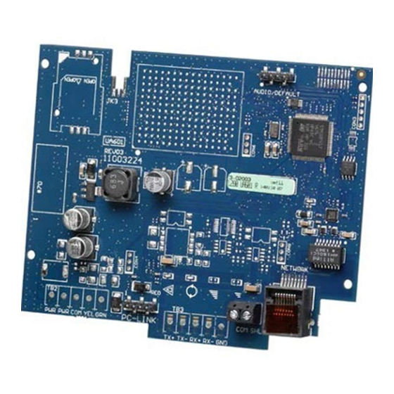
The TL280 (R) is an Ethernet alarm communicator that sends alarm communication to Sur- Gard System I- IP, II, III (SG- DRL3IP), IV (SG-DRL4IP), and 5 (SG-DRL5IP) central station receivers through Ethernet/Internet. -
Page 5: Technical Specifications, Ratings And Compatibility
[384] enable the desired back-up configuration (receiver 2 back-up for receiver 1 or receiver 3 back-up for receiver 1). Technical Specifications, Ratings and Compatibility Table 1: Communicator Ratings Model TL280(R) Power Supply Ratings 10.8-12.5 VDC. Power is supplied from the panel’s PC- Link header or a PCL- 422 module in remote cabinet installations. -
Page 6: Communicator Installation Configuration
Communicator Installation Configuration This Ethernet communicator shall be installed by service persons only (service person is defined as a person having the appro- priate technical training and experience necessary to be aware of hazards to which that person may be exposed to in per- forming a task and can also take measures to minimize the risks to that person or other persons). - Page 7 Jumper pins 4 and 5 Input Ratings: to reset. +10.8V ~ +12.5 VDC TL280(R) 100mA Network Link UA601 DSC Panel min. power requirements: YELLOW - 16.5 VAC 40 VA transformer; - 12 VDC 7Ah battery RJ-45 PC-LINK PCLINK_2 HS2016/2032/2064/2128 From NID...
-
Page 8: Initial Panel Programming
Table 3: RS-232 Connections 3rd Party Device Communicator Unused Unused Install Network Cable 1. Route the CAT 5 Ethernet cable through back of the panel and plug it into the communicator’s RJ45 jack. 2. Perform the following steps for initial power on of the panel with communicator installed: a. -
Page 9: Communicator Status Leds
Table 4: Communicator Path Programming Value Communication Method Auto Routing Ethernet 1 Ethernet 2 NOTE: Refer to panel manual for additional information 4. In panel section [350] ‘Communication Formats’, program the communication format as: CID (03) or SIA FSK (04). 5. -
Page 10: Communicator Troubleshooting
Ethernet Trouble (6 Flashes) This trouble is indicated when Ethernet link between the transmitter and the local switch or router is absent. This trouble will also be indicated if the unit fails to get Dynamic Host Control Protocol (DHCP) settings from the DHCP server. (Not active if Eth- ernet receivers are not programmed). -
Page 11: Ethernet Programming Options
Trouble Trouble Possible Indicator Trouble Possible Solution Indication Causes Digit Ensure that the Ethernet path has Internet connectivity. If using a static IP address, confirm that the gateway and subnet mask are entered correctly. Yellow LED – Receiver Not If the network has a firewall, ensure the network has the programmed 7 Flashes Available outgoing ports open (default UDP port 3060 and port 3065). - Page 12 [003] Ethernet Gateway IP Address Default (000.000.000.000) Enter the Ethernet gateway IP address of the communicator. The gateway IP address is required when a router is used on the local network to reach the destination IP address specified in section [001]. Format is 4 fields, each field is a 3 digit decimal num- ber.
- Page 13 NOTE: If no value is programmed and DHCP is used, the DHCP server will assign this value. If an address is programmed and DHCP is used, the programmed address will be used instead of the DHCP address. Programming Options [010] System Toggle Options 3 [1] Reserved.
- Page 14 Offset Standard Location Value Hours Abbreviation Argentina Time BEST Brazil Eastern Standard Time Cape Verde Time Greenwich Mean Time (UTC) Central European Time SAST South Africa Standard Time Arabic Standard Time IRST Iran Standard Time Gulf Standard Time Afghanistan Time Pakistan Time Indian Standard Time 5.75...
- Page 15 Communications Reporting Codes Table 8: Communications Reporting Codes Event Event Reporting Identifier ReportingCode Qualifier User/Zone Code Code [023] Panel Absent Trouble 0001 [024] Panel Absent Trouble Restore 0001 [026] Ethernet 1 Test Transmission 0001 [027] Ethernet 2 Test Transmission 0002 [030] FTC Restore 0001 [023] Panel Absent Trouble...
- Page 16 [030] FTC Restore Default (FF) Program 00 to disable this event transmission or FF to enable. This event will occur when an FTC Trouble on the system restores. [037] System Firmware Update Fail Default (FF); Program 00 to disable this event transmission or FF to enable. This event will occur when the panel firmware updated has failed.
- Page 17 [106] Ethernet Receiver 1 Domain Name Default ( ) Enter the domain name as 32 ASCII characters. Ethernet Receiver 2 Options [111] Ethernet Receiver 2 Account Code Default (0000000000) The account code is used by the central station to distinguish between transmitters. The account code is used when transmitting heartbeat signals to the central station receiver.
- Page 18 [226] Network Trouble Delay Default (0F) This option is used to program the delay, in minutes, for reporting/displaying a network trouble. Valid entries are 00 - FF (e.g., for a 10 minute network trouble delay enter: 0A). When this Timer is programmed as 00, Ethernet and Supervision troubles are not communicated or displayed on the keypad.
- Page 19 Resolve the low battery trouble to continue with system firmware low battery trouble; device/module) update process. System update pending - communication in Retry in a few minutes; if issue persists, contact DSC Tech progress Support. Firmware Update Sequence Change System firmware update successful None At least one module was not updated.
- Page 20 Response Description of Response Code Corresponding Action Code Reserved Enable remote firmware update in the communicator in order to Remote firmware update disabled perform remote system firmware update. Local Status Update States No action required. Communicator currently does not have any Firmware file empty firmware files.
- Page 21 [991] Firmware Version This section will display the current firmware version of the device. Update worksheets with new version after a flash update is completed. [992] Ethernet IP Address This section will display the IP address of the Ethernet connection. This value is programmed in section [001] or assigned by DHCP.
-
Page 22: Ethernet Cellular Programming Worksheets
[012] DLS Incoming Port Ethernet Cellular Programming Default (0BF6/3062) Valid range: 0000 - FFFF. Worksheets [013] DLS Outgoing Port System Options Default (0BFA/3066) Valid range: 0000 - FFFF. [001] Ethernet IP Address Default (000.000.000.000) [015] DLS Call-Up IP Default (000.000.000.000) [002] Ethernet IP Subnet Mask Default (255.255.255.000) [016] DLS Call-Up Port... - Page 23 [116] Ethernet Receiver 2 Domain Name Default ( ) [097] SA Call Up IP ____________________________________ Default (000.000.000.000) Ethernet Options [098] SA Call Up Port [124] Ethernet Test Transmission Time Default (0000) Valid range: 0000 - FFFF. Default (9999) Valid: 00-23(HH); 00-59(MM) [099] SA Password [125] Ethernet Test Transmission Cycle Default (FFFFFFFF) Valid range: 00000000 - FFFFFFFF.
- Page 24 [694] Integration Notification Port Default (0C00/0372) Valid range: 0000 - FFFF. [695] Integration Polling Port Default (0C01/3073) Valid range: 0000 - FFFF. [697] Integration Server DNS 32 ASCII characters. ____________________________________ [698] Integration Outgoing Port Default (0C04/3076) Valid range: 0000 - FFFF. [699] Integration Incoming Port Default (0BFF/3071) Valid range: 0000 - FFFF.
-
Page 25: Warranty
DigitalSecurityControlswillnot accept anyshipment whatsoever for which productspurchased fromDSC. Customproductsare onlywarranted to the prior authorization hasnot been obtained. extent that theydo not function upon delivery. In such cases, DSC can replace or Productswhich DigitalSecurityControlsdeterminesto be repairable willbe credit at itsoption. -
Page 26: Regulatory Information
EN50131 Compliant installations onlyaspart of a permanent sale or transfer of the HARDWARE, provided You 1. The TL280R, TL280 module ismonitored bythe controlpaneland it ispro- retain no copies, You transfer allof the SOFTWAREPRODUCT (including allcom- grammed via the programming menu (* 8, section [851] in the controlpanel. The... - Page 28 © 2015 Tyco Security Products. All Rights Reserved. Tech Support: 1-800-387-3630 (Canada & U.S.) or 905-760-3000 www.dsc.com The trademarks, logos, and service marksdisplayed on thisdocument are registered in the United States[or other countries]. Anymisuse of the trade- marksisstrictlyprohibited and Tyco willaggressivelyenforce itsintellectualpropertyrightsto the fullest extent of the law, including pursuit of criminalpro- secution wherever necessary.
Need help?
Do you have a question about the TL280 and is the answer not in the manual?
Questions and answers