Table of Contents
Advertisement
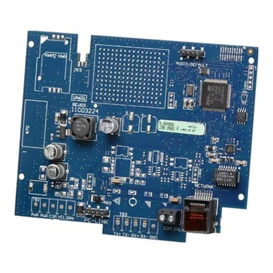
TL280(R)
Internet Alarm Communicator - International
Installation Guide V4.1
For installation manual, visit www.dsc.com
Warning: This manual contains information on limitations regarding product use and function and inform-
ation on the limitations as to liability of the manufacturer. The entire manual should be carefully read.
Advertisement
Table of Contents

Related Manuals for DSC TL280


Summary of Contents for DSC TL280
- Page 1 Internet Alarm Communicator - International Installation Guide V4.1 For installation manual, visit www.dsc.com Warning: This manual contains information on limitations regarding product use and function and inform- ation on the limitations as to liability of the manufacturer. The entire manual should be carefully read.
-
Page 2: Table Of Contents
WARNING: Installer please read carefully General Model Information Panel Mounting Features EN50131-1 Installation Requirements Technical Specifications, Ratings and Compatibility Communicator Installation Configuration Installing Communicator in Panel Initial Panel Programming Communicator Status LEDs Communicator Troubleshooting Ethernet Programming Options Ethernet Cellular Programming Worksheets Warranty EULA Regulatory Information... -
Page 3: Warning: Installer Please Read Carefully
Passive infrared motion detectorsoperate bysensing changesin temperature. WARNING: Installer please read However their effectivenesscan be reduced when the ambient temperature risesnear or above bodytemperature or if there are intentionalor unintentional carefully sourcesof heat in or near the detection area. Some of these heat sourcescould be heaters, radiators, stoves, barbecues, fireplaces, sunlight, steamvents, light- ing and so on. -
Page 4: General
A current list of compatible third party solutions can be found at www.dsc.com The TL280 (R) is an Ethernet alarm communicator that sends alarm communication to Sur- Gard System I- IP, II, III (SG- DRL3IP), IV (SG-DRL4IP), and 5 (SG-DRL5IP) central station receivers through Ethernet/Internet. -
Page 5: En50131-1 Installation Requirements
[384] enable the desired back-up configuration (receiver 2 back-up for receiver 1 or receiver 3 back-up for receiver 1). Technical Specifications, Ratings and Compatibility Table 1: Communicator Ratings Model TL280(R) Power Supply Ratings 10.8-12.5 VDC. Power is supplied from the panel’s PC-Link header or a PCL-422 module in remote cabinet installations. In remote cabinet... -
Page 6: Installing Communicator In Panel
performing a task and can also take measures to minimize the risks to that person or other persons). The Communicator shall be installed and used within an environment that provides the pollution degree max 2, overvoltages category II, in non- haz- ardous, indoor locations only. - Page 7 Jumper pins 4 and 5 Input Ratings: to reset. +10.8V ~ +12.5 VDC TL280(R) 100mA Network Link UA601 DSC Panel min. power requirements: YELLOW - 16.5 VAC 40 VA transformer; - 12 VDC 7Ah battery RJ-45 PC-LINK PCLINK_2 HS2016/2032/2064/2128 From NID...
-
Page 8: Initial Panel Programming
Table 3: RS-232 Connections Third Party Device Communicator Unused Unused Install Network Cable 1. Route the CAT 5 Ethernet cable through back of the panel and plug it into the communicator’s RJ45 jack. 2. Perform the following steps for initial power on of the panel with communicator installed: a. -
Page 9: Communicator Troubleshooting
Yellow Trouble LED This yellow LED will flash to indicate a trouble on the unit. The number of flashes indicates the type of trouble. See the table below for the coded flashes and the conditions which will activate the trouble status LED. Table 5: Yellow Trouble Status LED # of # of... -
Page 10: Ethernet Programming Options
Trouble Trouble Indic- Possible Indicator Trouble Possible Solution ation Causes Digit address and port number. Yellow LED Receiver This trouble is indicated when supervision is enabled and the unit is not able to – Supervision successfully communicate with the receiver. If this trouble persists, contact the central station. -
Page 11: Ethernet Cellular Programming Worksheets
[012] DLS Incoming Port Ethernet Cellular Programming Default (0BF6/3062) Valid range: 0000 - FFFF. Worksheets [013] DLS Outgoing Port System Options Default (0BFA/3066) Valid range: 0000 - FFFF. [001] Ethernet IP Address Default (000.000.000.000) [015] DLS Call-Up IP Default (000.000.000.000) [002] Ethernet IP Subnet Mask Default (255.255.255.000) [016] DLS Call-Up Port... - Page 12 [036] Panel Firmware Update Successful [112] Ethernet Receiver 2 DNIS Default (FF) Program 00 disable or FF enable. Default (000000) Valid range: 000000 - 0FFFFF. [037] Panel Firmware Update Fail [113] Ethernet Receiver 2 Address Default (FF) Program 00 disable or FF enable. Default (000.000.000.000) [095] SA Incoming Local Port [114] Ethernet Receiver 2 UDP Remote Port...
-
Page 13: Warranty
Default (0C04/3076) Valid range: 0000 - FFFF. ibilityfor the proper selection, installation, operation and maintenance of any productspurchased fromDSC. Customproductsare onlywarranted to the extent that theydo not function upon delivery. In such cases, DSC can replace or [699] Integration Incoming Port credit at itsoption. -
Page 14: Eula
RISK - IN ANYEVENT, IF ANYSTATUTEIMPLIESWARRANTIESOR arrangement or contract. If You do not agree to the termsof thisEULA, DSC is CONDITIONSNOT STATED IN THISLICENSEAGREEMENT, DSC’SENTIRE unwilling to license the SOFTWAREPRODUCT to You, and You have no right to LIABILITYUNDER ANYPROVISION OF THISLICENSEAGREEMENT SHALL BE use it. -
Page 15: Regulatory Information
Regulatory Information EN50131 Compliant installations 1. The TL280R, TL280 module ismonitored bythe controlpaneland it ispro- grammed via the programming menu (* 8, section [851] in the controlpanel. The interface isconnected to the PC-Linkbusasshown in the diagramincluded in this manual. - Page 16 © 2015 Tyco Security Products. All Rights Reserved. Tech Support: 1-800-387-3630 (Canada & U.S.) or 905-760-3000 www.dsc.com The trademarks, logos, and service marksdisplayed on thisdocument are registered in the United States[or other countries]. Anymisuse of the trademarksisstrictlypro- hibited and Tyco willaggressivelyenforce itsintellectualpropertyrightsto the fullest extent of the law, including pursuit of criminalprosecution wherever necessary. All trademarksnot owned byTyco are the propertyof their respective owners, and are used with permission or allowed under applicable laws.
Need help?
Do you have a question about the TL280 and is the answer not in the manual?
Questions and answers