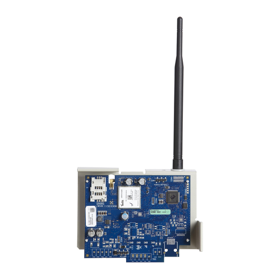
DSC TL280LE Installation Manual

DSC TL280LE Installation Manual

Internet and lte/hspa dual-path alarm communicator;lte/hspa alarm communicator;cellular alarm communicator;internet and hspa dual-path alarm communicator; internet alarm communicator
Hide thumbs Also See for TL280LE:
Table of Contents

Advertisement

Internet and LTE/HSPA Dual-Path Alarm
Internet and HSPA Dual-Path Alarm Communicator
WARNING: This manual contains information on limitations regarding product use and
function and information on the limitations as to the liability of the manufacturer. The
entire manual should be carefully read.
PLEASE NOTE THAT NOT ALL MODELS AND FEATURES LISTED ARE AVAILABLE IN
ALL MARKETS.
TL280LE(R)
Communicator
LE2080(R)
LTE/HSPA Alarm Communicator
3G2080(R)E
Cellular Alarm Communicator
TL2803G(R)E
TL280(R)E
Internet Alarm Communicator
Installation Manual v5.1

Advertisement

Table of Contents
loading
Need help?

Need help?

Do you have a question about the TL280LE and is the answer not in the manual?

Questions and answers

Subscribe to Our Youtube Channel

Summary of Contents for DSC TL280LE

  • Page 1 TL280LE(R) Internet and LTE/HSPA Dual-Path Alarm Communicator LE2080(R) LTE/HSPA Alarm Communicator 3G2080(R)E Cellular Alarm Communicator TL2803G(R)E Internet and HSPA Dual-Path Alarm Communicator TL280(R)E Internet Alarm Communicator Installation Manual v5.1 WARNING: This manual contains information on limitations regarding product use and function and information on the limitations as to the liability of the manufacturer.
  • Page 2: Table Of Contents

    FTC Trouble (9 Flashes) Module Configuration Trouble (12 Flashes) Red Network Connection Status LED (Green LED 1) (Green LED 2) and (Yellow LED) Signal Strength Network Activity LEDs - Red and Green(TL2803G(R)E / TL280LE(R) only) Communicator Troubleshooting Ethernet/Cellular Programming Options System Options...
  • Page 3 System Test Options Ethernet Receiver 1 Options Ethernet Receiver 2 Options Ethernet Options Cellular Receiver 1 Options Cellular Receiver 2 Options Cellular Options SMS Event Notification/Command and Control Options External Event Label Programming Receiver Diagnostic Testing System Information (Read Only) System Reset Defaults Ethernet Cellular Programming Worksheets System Options...
  • Page 4: Warning: Installer Please Read Carefully

    do not provide volumetric area protection. They have multiple beams of WARNING: Installer please read detection and motion can only be detected in unobstructed areas covered by these beams. They cannot detect motion which occurs carefully behind walls, ceilings, floor, closed doors, glass partitions, glass doors or windows.
  • Page 5: General

    Models TL2803GRE- EU , TL2803GE- EU , 3G2080RE- EU and 3G2080E- EU are for Europe/In- ternational and cover the following bands: 900/1800 MHz. Models TL280LER , TL280LE, LE2080R , LE2080 are for North America and support LTE bands B2, B4, B5, B12 and B13 and WCDMA bands B2 and B5.
  • Page 6: Panel Mounting

    Internet Protocol (IP) transmission of panel and communicator events over Ethernet/Internet and/or HSPA/GPRS. The cellular performance of the LE2080(R), TL280LE(R), 3G2080(R) E or TL2803G (R) E com- municators depend greatly on the LTE(4G)/HSPA(3G) network coverage in the local area.
  • Page 7: Ratings Compatibility

    Ratings Compatibility Table 1: Communicator Ratings 3G2080(R)E /LE2080 TL2803G(R)E/TL280LE TL280(R)E Model Internet only Cellular only Internet and Cellular Power Supply Ratings 10.8-12.5 VDC Power is supplied from the panel’s PC-Link header or PCL-422 module in remote Input Voltage cabinet installations. In remote cabinet installations, the PCL-422 module located with the communicator is powered by an HSM2204 or an HSM2300.
  • Page 8: Communicator Installation Configuration

    enabled or disabled. When encryption is enabled, the central station will configure the device to encrypt communications the next time the communicator module performs a communication to that receiver. NOTE: Packets will start being encrypted only after the next event is sent to that receiver, or if the unit is restarted.
  • Page 9 c. Place the bracket on a flat, solid surface. Hold the communicator component side up and orient the 4 holes on the communicator with the 4 standoffs protruding from the bracket. Push the com- municator firmly and evenly onto the standoffs until it is securely attached to the mounting bracket.
  • Page 10 Screw WARNING! - 3G2080(R) E/TL2803G(R) E/LE2080(R)/TL280LE(R) modules are power limited. Do not route any wiring over the circuit board. Maintain at least 1in. (25.4mm) separation between circuit board and wiring. A minimum of ¼ in. (7mm) separation must be maintained at all points between non-power limited wiring and power limited wiring.
  • Page 11 120mA (TL2803G(R)E/TL280LE(R). Jumper pins 4 and 5 to reset 400mA alarm Network Link - Yellow DSC Panel minimum power requirements: From NID use only CAT5 supervised 16.5 VAC 40 VA transformer 12 VDC 7Ah battery maximum cable length 100m (328 feet)
  • Page 12: Communicator Placement Test

    communicated to all programmed receivers. If this is the first time the communicator has been powered up in the panel, the module will initiate communications to C24 Communications to request remote programming. NOTE: During radio reset, the two green LEDs will flash alternately. NOTE: Initialization may take several minutes to complete.
  • Page 13: Initial Panel Programming

    Trouble’ (2 flashes) and the unit can not be programmed via the PC-LINK cable. Activating the Communicator with C24 Communications Installation of the 3G2080(R)E / LE2080(R) or TL2803G(R)E / TL280LE(R) requires activation with C24 Communications in order to operate. Please contact the central station (C24 Communications Master Reseller) to confirm the required steps to activate/program the communicator.
  • Page 14: Sms Commands

    through programming section [851]. The security system only responds to SMS messages sent from designated phone numbers (pro- grammed in section [851]>[311]-[328]). SMS Commands Stay arm the system Away arm the system Night arm the system Disarm the system Activate command output 1 Activate command output 2 Activate command output 3 Activate command output 4...
  • Page 15: Sim Lock Trouble (4 Flashes)

    This trouble is indicated when the system account code or the receiver account have not been pro- grammed. Disabled receivers are excluded. Red Network Connection Status LED TL280(R)E / TL280LE(R) / TL2803G(R)E only BLINKING: Indicates communications in progress. Once quickly for outgoing Ethernet transmission.
  • Page 16: Network Activity Leds - Red And Green(Tl2803G(R)E / Tl280Le(R) Only)

    CSQ Level is 4 or less. The communicator signal strength can be viewed remotely with C24 Com- munications. Network Activity LEDs - Red and Green(TL2803G(R)E / TL280LE(R) only) Ethernet Activity: Red LED will blink quickly once for transmit, or twice for receive.
  • Page 17 Trouble Trouble Possible Indicator Trouble Possible Solution indication Causes Digit Communicator Enabled). Ensure the PC-LINK cable between the panel and LED – 2 Supervision communicator is connected properly (not reversed) and Flashes Trouble is securely in place. Confirm that cellular service is available and active in the area.
  • Page 18: Ethernet/Cellular Programming Options

    Trouble Trouble Possible Indicator Trouble Possible Solution indication Causes Digit Ensure that a valid account code has been entered in Flashes Trouble these sections. All LEDs Disconnect power, then reconnect power to the Boot Loader flashing communicator module. Failed together Red and The unit is still initializing please wait while the unit gets Yellow...
  • Page 19 Receiver Window: This is the supervision timeout that must be configured at the central station receiver. Recommended Values: This is the recommended heartbeat interval that should be programmed into the communicator. [005] System Toggle Options [1] Ethernet Receiver 1 Supervised (TL2803G(R)E only) Default (OFF) ON: Ethernet receiver 1 will be supervised and heartbeats will be sent to Ethernet receiver 1 based on the supervision interval programmed in section [004].
  • Page 20: Programming Options

    OFF: Ethernet receiver 2 is disabled. [3] Reserved [4] Cellular receiver 1 is enabled. Default (ON) OFF for TL2803G(R)E. ON: Cellular receiver 1 is enabled. OFF: Cellular receiver 1 is disabled. [5] Cellular receiver 2 is enabled. Default (ON) OFF for TL2803G(R)E. ON: Cellular receiver 2 is enabled.
  • Page 21 OFF: Visual verification is disabled. [3] Video On Demand. Default (OFF) ON: Video On Demand is enabled. OFF: Video On Demand is disabled. [4] Reserved. [5] Reserved. [6] Reserved. [7] Reserved. [8] Reserved. [011] Installer Code Default (CAFE) Program the installer code for the communicator module. The installer code will be required when pro- gramming the communicator module.
  • Page 22 Offset Standard Location Value Hours Abbreviation -3.5 Newfoundland Standard Time Argentina Time BEST Brazil Eastern Standard Time Cape Verde Time Greenwich Mean Time (UTC) Central European Time SAST South Africa Standard Time Arabic Standard Time IRST Iran Standard Time Gulf Standard Time Afghanistan Time Pakistan Time Indian Standard Time...
  • Page 23: Communications Reporting Codes

    Communication Standard - October 1997. This format will send the account code along with its data transmission. The transmission will look similar to the following at the receiver. NOTE: This section shall sync with PowerSeries Neo panels version 1.00 or higher. Example: Nri0 ET001 where: N = New Event;...
  • Page 24 Interval 2: If the test transmission fails to the secondary receiver, it will back up to the primary receiver. If the test transmission fails to the primary receiver, an FTC trouble will be generated. Test Transmission Unique to Primary and Secondary Receivers: Set Ethernet section [026] to (FF);...
  • Page 25: Ethernet Receiver 1 Options

    [096] SA Outgoing Local Port Default (0C14/3093) [097] SA Call Up IP Default (000.000.000.000) [098] SA Call Up Port Default (0000) [099] SA Password Default (FFFFFFFF) Ethernet Receiver 1 Options [101] Ethernet Receiver 1 Account Code Default (0000000000) The account code is used by the central station to distinguish between transmitters. This account code is used when transmitting heartbeat signals to the central station receiver.
  • Page 26: Ethernet Options

    NOTE: If both Ethernet receiver 2 and cellular receiver 2 are the same receiver (IP and port number are identical), Ethernet receiver 2 account will be used for Ethernet and cellular. [112] Ethernet Receiver 2 DNIS Default (000000) The DNIS is used in addition to the account code to identify the communicator module at the central sta- tion.
  • Page 27: Cellular Receiver 1 Options

    NOTE: Minimum value is 000005 minutes. Programming an interval that is less than 5 minutes will dis- able test transmission. Cellular Receiver 1 Options [201] Cellular Receiver 1 Account Code Default (0000000000) The account code is used by the central station to distinguish between transmitters. This account code is used when transmitting heartbeat signals to the central station receiver.
  • Page 28: Cellular Options

    [214] Cellular Receiver 2 Port Default (0BF5/3061) This section defines the port of cellular receiver 2. Change the value of this port when the installation is loc- ated behind a firewall and must be assigned a particular port number, as determined by the central sta- tion system administrator.
  • Page 29: Sms Event Notification/Command And Control Options

    [228] Voice Call Back Time Default (0A) Valid entries are 00 - FF. [229] Voice Call Back Number Default ( ) 32 digit phone number. SMS Event Notification/Command and Control Options When an event is triggered by the panel and SMS notification is ON in section [301] toggle option [1], an SMS message is created and sent to the SMS telephone numbers programmed in sections [311]- [342] for event types specified in sections [343]- [374] if toggle [7] is ON.
  • Page 30 [2] SMS Notification Tamper/Restore Default (ON) [3] SMS Notification Opening/Closing Default (ON) [4] SMS Notification System Maintenance Default (ON) [5] SMS Notification System Test Default (ON) [6] SMS Notification Internal Events Default (ON) [7] SMS Notification Enabled Default (ON) [8] SMS Command and Control Enabled Default (ON) [375]-[406] SMS Phone Number 1-32 Partition Option Default (00) 01-32 assigns the phone number to a partition.
  • Page 31 [1] UDP Polling Default (OFF) [2] TCP Polling Default (OFF) [3] Real-time Notification Default (OFF) [4] Notification Follows Poll Default (OFF) [5] Reserved [6] Reserved [7] Reserved [8] Reserved [427] Session 1 Interactive Polling Interval in Seconds Default (000A) This option controls the polling interval from the alarm panel to the integration interface for the purpose of optimizing data usage.
  • Page 32 [438] Session 1 Notification Zone 33-40 [439] Session 1 Notification Zone 41-48 Toggle Zone 33 Default (ON) Zone 41 Default (ON) Zone 34 Default (ON) Zone 42 Default (ON) Zone 35 Default (ON) Zone 43 Default (ON) Zone 36 Default (ON) Zone 44 Default (ON) Zone 37 Default (ON) Zone 45 Default (ON)
  • Page 33 Zone 102 Default (ON) Zone 110 Default (ON) Zone 103 Default (ON) Zone 111 Default (ON) Zone 104 Default (ON) Zone 112 Default (ON) [448] Session 1 Notification Zone 113-120 [449] Session 1 Notification Zone 121-128 Toggle Zone 113 Default (ON) Zone 121 Default (ON) Zone 114 Default (ON) Zone 122 Default (ON)
  • Page 34 [724] Lifestyle Zone 17-24 Toggle [725] Lifestyle Zone 25-32 Toggle Zone 17 Default (ON) Zone 25 Default (ON) Zone 18 Default (ON) Zone 26 Default (ON) Zone 19 Default (ON) Zone 27 Default (ON) Zone 20 Default (ON) Zone 28 Default (ON) Zone 21 Default (ON) Zone 29 Default (ON) Zone 22 Default (ON)
  • Page 35: External Event Label Programming

    Zone 86 Default (ON) Zone 94 Default (ON) Zone 87 Default (ON) Zone 95 Default (ON) Zone 88 Default (ON) Zone 96 Default (ON) [734] Lifestyle Zone 97-104 Toggle [735] Lifestyle Zone 105-112 Toggle Zone 97 Default (ON) Zone 105 Default (ON) Zone 98 Default (ON) Zone 106 Default (ON) Zone 99 Default (ON)
  • Page 36 Event [Section] Label Default Label Event [Section] Label Default Label [757] Sprinkler Alarm [756] Sprinkler Alarm (Sprinkler Alarm) (Sprinkler Alarm Restore) Restore [759] Water Level Alarm (Water Level Alarm [758] Water Level Alarm (Water Level Alarm) Restore Restore) [760] Low Temperature (Low Temperature [761] Low Temperature (Low Temperature Alarm...
  • Page 37 Event [Section] Label Default Label Event [Section] Label Default Label Cancelled Cancelled) [813] Disarmed After [812] Late to Close (Late to Close) (Disarmed After Alarm) Alarm [814] Alarm Ocurred After (Alarm Ocurred After [815] Exit Fault (Exit Fault) Arming Arming) [817] Armed With Zones (Armed With Zones [816] Cold Start...
  • Page 38: Receiver Diagnostic Testing

    Event [Section] Label Default Label Event [Section] Label Default Label [869] Keypad Message (Keypad Message) [870] Function Successful (Successful) [871] Function Failure (Unsuccessful) [872] Invalid Command (Invalid Command) [873] System Stay Armed (Stay Armed) [874] System Away Armed (Away Armed) [875] System Night [876] System Disarmed (Night Armed)
  • Page 39 Resolve the low battery trouble to continue with (Any low battery trouble; system firmware update process. device/module) System update pending - Retry in a few minutes; if issue persists, contact DSC communication in progress Tech Support. Firmware Update Sequence Change System firmware update successful None At least one module was not updated.
  • Page 40 Response Description of Response Code Corresponding Action Code Contact DSC Tech Support, describe the action General device firmware transfer attempted with the system and supply them with the failure Response Code in Section [983]. Firmware Update Status System ready to update.
  • Page 41 Signal Signal Signal Signal Signal Indicator Indicator Level Level Action Required Strength Level [dBm] Status Relocate panel or install external antenna. -108 ~ - Relocate panel or install external 1 Bar 1 - 4 weak antenna if yellow trouble LED has 5 flashes.
  • Page 42: System Reset Defaults

    [989] DNS 2 IP Address This section will display the IP address of DNS Server 2. This is useful when the unit is configured for DHCP and the IP address assigned to the device by the DHCP Server is needed. This value is pro- grammed in section [008] or assigned by DHCP.
  • Page 43: Ethernet Cellular Programming Worksheets

    Default (0BF6/3062) Valid range: 0000 - FFFF. [3] Supervision Type (OFF). [4] Primary Communications Path. [013] DLS Outgoing Port [OFF] TL2803G(R)E; TL280LE(R) Default (0BFA/3066) Valid range: 0000 - FFFF. [ON] 3G2080(R)E; LE2080(R). [5] Redundant Communications (OFF). [015] DLS Call-Up IP [6] Remote Firmware Upgrade (ON).
  • Page 44: System Test Options

    System Test Options [104] Ethernet Receiver 1 UDP Remote Port [026] Ethernet 1 Test Transmission Default (0BF5/3061) Valid range: 0000 - FFFF. Default (FF) Program 00 disable or FF enable. [105] Ethernet Receiver 1 UDP Local Port [027] Ethernet 2 Test Transmission Default (0BF4/3060)Valid range: 0000 - FFFF.
  • Page 45: Cellular Receiver 2 Options

    [226] Network Trouble Delay Default (0F) [204] Cellular Receiver 1 Port Valid entries from, 00 to FF. Default (0BF5/3061) Valid range: 0000 - FFFF. [227] Voice Call Timeout [205] Cellular Receiver 1 APN Default (00) 32 ASCII characters. Valid entries from, 00 to FF. ____________________________________ [206] Cellular Receiver 1 Domain Name [228] Voice Call Back Time...
  • Page 46 Default (ON) [5] Reserved [5] SMS Notification System Test Default (ON) [6] Reserved [6] SMS Notification Internal Events Default [7] Reserved (ON). [8] Reserved [7] SMS Notification Enabled Default (ON). [427] Session 1 Interactive Polling Interval [8] SMS Command and Control Enabled Default (000A) Valid range: 0000 - FFFF seconds.
  • Page 47 [4] Zone 20 Default (ON) [3] Zone 59 Default (ON) [5] Zone 21 Default (ON) [4] Zone 60 Default (ON) [6] Zone 22 Default (ON) [5] Zone 61 Default (ON) [7] Zone 23 Default (ON) [6] Zone 62 Default (ON) [8] Zone 24 Default (ON) [7] Zone 63 Default (ON) [8] Zone 64 Default (ON)
  • Page 48 [2] Zone 98 Default (ON) [7] Lighting Notifications (Neo 1.4+ only) [3] Zone 99 Default (ON) [8] Temperature Notifications (Neo 1.4+ only) [4] Zone 100 Default (ON) [692] Session 2 Notification Control [5] Zone 101 Default (ON) [1] Alarm and Alarm Restore Notifications [6] Zone 102 Default (ON) [2] Tamper and Tamper Restore Notifications [7] Zone 103 Default (ON)
  • Page 49 [716] Lifestyle Reset Window [3] Zone 35 Default (ON) Default (0E10) Valid range: 0000 - FFFF. [4] Zone 36 Default (ON) [5] Zone 37 Default (ON) [720] Local debug TCP Port [6] Zone 38 Default (ON) Default (0000) Valid range: 0000 - FFFF. [7] Zone 39 Default (ON) [8] Zone 40 Default (ON) [722] Lifestyle Zone 1-8 Toggle...
  • Page 50: External Event Label Programming

    [736] Lifestyle Zone 113-120 Toggle [2] Zone 74 Default (ON) [1] Zone 113 Default (ON) [3] Zone 75 Default (ON) [4] Zone 76 Default (ON) [2] Zone 114 Default (ON) [5] Zone 77 Default (ON) [3] Zone 115 Default (ON) [6] Zone 78 Default (ON) [4] Zone 116 Default (ON) [7] Zone 79 Default (ON)
  • Page 51 _______________________________________ [748] High Temperature Alarm Default (High Temperature Alarm) [766] Water Alarm _______________________________________ Default (Flood Alarm) _______________________________________ [749] High Temperature Alarm Restore Default (High Temperature Alarm Restore) [767] Water Alarm Restore _______________________________________ Default (Flood Alarm Restore) _______________________________________ [750] Medical Alarm [768] Quick Bypass Alarm Default (Medical Alarm) ______________________________________...
  • Page 52 ______________________________________ [783] Panel Auxiliary Power Restore Default (Auxiliary Power Restore) [801] Module Trouble Restore _______________________________________ Default (Module Trouble Restore) _______________________________________ [784] Panel Battery Trouble Default (Battery Trouble) [802] Wireless/AML Device Trouble _______________________________________ Default (Device Trouble) _______________________________________ [785] Panel Battery Restore [803] Wireless/AML Device Restore Default (Battery Trouble Restore) _______________________________________...
  • Page 53 _______________________________________ [818] Zone Bypassed Default (Zone Bypassed) [836] Firmware Update Successful _______________________________________ Default (Firmware Update Successful) _______________________________________ [819] Zone Unbypassed Default (Zone Unbypassed) [837] Firmware Update Fail _______________________________________ Default (Firmware Update Fail) _______________________________________ [820] Burglary Verified [838] Delinquency Default (Burglary Verified) _______________________________________ Default (Delinquency) _______________________________________...
  • Page 54: Receiver Diagnostic Testing

    _______________________________________ [856] Activate Command Output 2 Default (Activate Command Output 2) [874] System Away Armed _______________________________________ Default (Away Armed) _______________________________________ [857] Activate Command Output 3 Default (Activate Command Output 3) [875] System Night Armed _______________________________________ Default (Night Armed) _______________________________________ [858] Activate Command Output 4 [876] System Disarmed Ready Default (Activate Command Output 4) _______________________________________...
  • Page 55: System Information (Read Only)

    [964] Voice Volume [979] Cellular Network CSQ Default (04) [980] Radio Reset Codes Valid entries from, 00 to FF. [981] Radio Type [982] Radio Firmware Version [965] Microphone Gain [983] Firmware Update Diagnostics Section Default (01) [984] Communicator Status Valid entries from, 00 to FF. [985] Radio Initialization Status [986] System Toggle Options 4 [966] SMS Recovery Hour...
  • Page 56: Limited Warranty

    DSC. Custom products are only warranted to the extent that they do not function upon delivery. In such cases, DSC Installer’s Lockout can replace or credit at its option.
  • Page 57: Regulatory Information

    You may not make any changes or modifications to the Soft- DSC NEITHER ASSUMES NOR AUTHORIZES ANY OTHER ware, without the written permission of an officer of DSC. You may not PERSON PURPORTING TO ACT ON ITS BEHALF TO MOD8IFY...
  • Page 58 Internet. The communication paths can UL/ULC Installation Requirements be used in a standalone mode in conjunction with a DSC alarm NOTE: For equipment used at the protected premises and intended to system (compatible DSC alarm control panel models: facilitate IP communications (hubs, routers, NIDs, Digital Subscriber HS2128/064/032/016).
  • Page 59 • For UL Commercial Burglaryapplications the TL2803G (R) E/ 3G2080R / TL280(R)E / LE2080(R) / TL280LE(R) can be used as dual signalling line communication system (cellular and Ethernet chan- nels used in redundant configuration), standard line security and as encrypted line security.
  • Page 60 © 2017 Tyco Security Products. All Rights Reserved. Tech Support: 1-800-387-3630 (Canada & U.S.) or 905-760-3000 www.dsc.com The trademarks, logos, and service marks displayed on this document are registered in the United States [or other countries]. Any misuse of the trademarks is strictly prohibited and Tyco will aggressively enforce its intellectual property rights to the fullest extent of the law, including pursuit of criminal prosecution wherever necessary.

Table of Contents

Save PDF